EP0198379A2 - Preneur à mâchoire de prise échangeable - Google Patents
Preneur à mâchoire de prise échangeable Download PDFInfo
- Publication number
- EP0198379A2 EP0198379A2 EP86104705A EP86104705A EP0198379A2 EP 0198379 A2 EP0198379 A2 EP 0198379A2 EP 86104705 A EP86104705 A EP 86104705A EP 86104705 A EP86104705 A EP 86104705A EP 0198379 A2 EP0198379 A2 EP 0198379A2
- Authority
- EP
- European Patent Office
- Prior art keywords
- bolt
- coupling
- gripping device
- gripper
- gripper jaw
- Prior art date
- Legal status (The legal status is an assumption and is not a legal conclusion. Google has not performed a legal analysis and makes no representation as to the accuracy of the status listed.)
- Granted
Links
- 230000008878 coupling Effects 0.000 claims abstract description 94
- 238000010168 coupling process Methods 0.000 claims abstract description 94
- 238000005859 coupling reaction Methods 0.000 claims abstract description 94
- 230000000903 blocking effect Effects 0.000 claims description 4
- 230000000295 complement effect Effects 0.000 claims description 3
- 239000002655 kraft paper Substances 0.000 description 2
- 229920003002 synthetic resin Polymers 0.000 description 2
- 239000000057 synthetic resin Substances 0.000 description 2
- 230000032258 transport Effects 0.000 description 2
- 241001295925 Gegenes Species 0.000 description 1
- 230000007423 decrease Effects 0.000 description 1
- 238000006073 displacement reaction Methods 0.000 description 1
- 238000003754 machining Methods 0.000 description 1
- 239000011295 pitch Substances 0.000 description 1
Images

Classifications
-
- B—PERFORMING OPERATIONS; TRANSPORTING
- B25—HAND TOOLS; PORTABLE POWER-DRIVEN TOOLS; MANIPULATORS
- B25J—MANIPULATORS; CHAMBERS PROVIDED WITH MANIPULATION DEVICES
- B25J15/00—Gripping heads and other end effectors
- B25J15/04—Gripping heads and other end effectors with provision for the remote detachment or exchange of the head or parts thereof
- B25J15/0475—Exchangeable fingers
Definitions
- the spring arrangement is pretensioned in the longitudinal direction of the bolt opening, that is to say transversely to the coupling plug, and constantly strives to press the bolt into its locked position.
- the gripper jaw can only assume a precisely predetermined position with respect to the coupling plug if the bolt is guided without play in the bolt opening of the gripper jaw and in the lateral recess of the coupling plug, a condition that cannot be met in practice in the long run.
- the coupling plug has a shoulder-like approach on which the gripper jaw should rest; however, the spring arrangement can, if at all, exert only a small force on the gripper jaw in relation to its pretension in the direction of the attachment of the coupling plug.
- the bolt can be pressed into its release position with a rod-shaped tool against the resistance of the spring arrangement. If the coupling plug has been reinserted into the coupling opening for the re-use of the gripper jaw, it cannot be determined with the usual control of the gripping device whether the bolt has returned to its locked position or has jammed in its release position. There is therefore a risk that the gripper jaw is used without being securely locked to the coupling plug.
- the invention has for its object to develop a gripping device of the type described above such that its at least one interchangeable gripper jaw by means of a control, as is customary for such gripper devices, can be locked and detached from it reliably and in precise positional assignment to the coupling plug .
- the gripping device can be moved with drive means, which are assigned to it anyway in a known manner, in such a way that the second engagement surface of the bolt according to the invention abuts the jaw rest. While the bolt reaches its locking position in this way, a tension is created in the spring arrangement in the longitudinal direction of the coupling plug, which holds the gripper jaw in a position which is fixed, for example, by a stop surface on the supporting coupling part.
- the gripping device according to the invention is particularly suitable for handling machines (robots) and generally has two gripper jaws, each of which transports a workpiece from one processing station to the next.
- the gripping device according to the invention is also suitable Direction also for the transport of tools and for holding workpieces or tools during machining.
- the gripping device according to the invention can be configured similar to a three-jaw chuck with three gripper jaws for clamping a workpiece on an automatic lathe. In all these cases, it may be sufficient if one of two or more interacting gripper jaws can be exchanged in the manner according to the invention; in other cases, all gripper jaws of the gripping device can be exchanged.
- the spring arrangement is preferably arranged between the supporting coupling part, in which the coupling plug is guided in its longitudinal direction, and a head of the coupling plug.
- the coupling plug it is also possible for the coupling plug to be rigidly connected to the supporting coupling part and for the spring arrangement to be arranged between the interchangeable gripper jaw and the bolt.
- the coupling plug is attached to the interchangeable gripper jaw and the bolt is guided in the supporting coupling part.
- At least one taper pin is attached to the load-bearing coupling part or to the exchangeable gripper jaw parallel to the coupling plug, to which a complementary centering device on the gripper jaw or on the load-bearing coupling part is assigned.
- the coupling plug can engage in the coupling opening with considerable play, since it does not have to ensure the positioning of the interchangeable gripper jaw in relation to the supporting coupling part, but only has to transmit the force of the spring arrangement.
- Other known means, for example complementary ones can also be provided for the exact positioning of the gripper jaw in relation to the supporting coupling part Flat serrations, also known as Hirth tooth clutches.
- the latch has a depression in its wedge surface into which a foot of the coupling plug can be snapped. This results in a positive connection in the locking position of the bolt, which secures the bolt particularly reliably against unintentional displacement.
- the gripper jaw can contain at least one latching device, which strives to hold the bolt in its release position.
- the gripper jaw can contain at least one latching device which strives to hold the bolt in its locked position.
- the cheek rest expediently has a freely cantilevered holding plate above a storage surface, which fits into the bolt opening and with which the bolt can be moved into the release position.
- the two measures described above can be further developed jointly in that the holding plate has at least one recess into which the latching device assigned to the locking position of the bolt can be latched when the bolt is moved into the release position.
- the jaw rest can have a stop opposite the holding plate, against which the bolt with its second engagement surface can be pressed in order to be moved into the locked position.
- the jaw rest has a two-sided cantilevered holding plate and on both sides thereof a storage surface for a gripper jaw and a stop for the second engagement surface of the associated bolt.
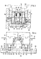
- the gripping device shown has a only partially indicated gripper housing 10 with a pair of parallel guides 12, on which two base jaws 14 are slidably guided.
- the gripper housing 10 also contains a drive, not shown, of a known type, for example an electric servo motor, with which the base jaws can be moved in opposite directions via a known gear, also not shown.
- the gear unit can, for example, consist of a threaded spindle with two opposing threads and associated nuts, the threads having the same or different pitches, depending on whether the base jaws 14 are to be moved through the same or different paths.
- a supporting coupling part 18, which protrudes from the gripper housing 10 is fastened with screws 16, in the example shown downward. If here and below we speak from below and above, this refers to the representation in FIGS. 1, 3 and 4; in reality, the gripping device shown can take any position in space.
- An interchangeable gripper jaw 20 is coupled to each of the two supporting coupling parts 18 by means of a coupling, which is described in more detail below.
- Each of the two couplings includes a coupling opening 22 of circular cross section, as shown in FIGS. 1, 3 and 4, and a locking opening 24 of rectangular cross section arranged transversely thereto, both of which are formed in the relevant gripper jaw 20.
- a coupling plug 26 is slidably guided, which is designed as an essentially cylindrical bolt.
- the coupling plug 26 has a head 28 at its upper end and, in the vicinity of its lower end, a lateral recess 30 in the form of an annular groove with a conical boundary surface 32, to which a foot 34 connects.
- a flat, essentially rectangular bolt 36 is guided in the bolt opening 24, into which a slot 38 is made from one of its narrow sides.
- the slot 38 has a width in the region of its end that is only slightly larger than the diameter of the coupling plug 26 in the region of the recess 30; outwardly, the slot 38 widens to a width that is slightly larger than the diameter of the foot 34.
- a wedge surface 40 is formed on the underside of the latch 36 in such a way that the thickness of the latch decreases toward the narrow side from which the slot 38 originates.
- a substantially conical recess 42 is formed around the end of the slot 38 on the underside of the latch 36, into which the foot 34 can snap with its upper boundary surface 32.
- each. one of the two gripper jaws 20 arranged latch 36 are shown in Fig. 1 to 3 in a locked position in which they prevent the associated hitch tion plug 26 is pulled up out of the associated gripper jaw 20. In FIG. 4, however, each of the two latches 36 is shown in a release position in which the associated coupling plug 26 can be pulled out upwards by expanding the slot 38.
- each of the two gripper jaws 20 there is a resilient latching device 44 which snaps into a notch 46 of the associated latch 36 when the latch is in its release position. Furthermore, two latching devices 48 are arranged in each of the two gripper jaws 20, each of which latches into a notch 50 of the associated bolt 36 when the latter is in its locked position.
- Each of the two bolts 36 also has an engagement surface 52 facing the other bolt for forces in the direction of the release position and an engagement surface 54 facing away from the other bolt for forces in the direction of the blocking position; in the example shown, these attack surfaces are formed by the two end faces of the bolt.
- Each of the two load-bearing coupling parts 18 has a cylindrical cavity 56 machined from above, which is closed at the top by a screwed-on cover 58.
- the head 28 and the adjoining part of the associated coupling plug 26 and a spring arrangement 60 are accommodated in the cavity 56.
- the spring arrangement 60 is a plate spring assembly, which is arranged between the head 28 of the coupling plug 26 and a shoulder of the cavity 56.
- the coupling plug 26 is displaceable against the resistance of the spring arrangement 60 with respect to the load-bearing coupling part 18 and is held tensioned in the locked position of the associated bolt 36, as a result of which Gripper jaw 20 and coupling part 18 are clamped together.
- the coupling plug 26 has sufficient radial play with respect to the coupling part 18 and the gripper jaw 20 so that it cannot become jammed.
- the required exact positioning of each of the two interchangeable gripper jaws 20 in relation to the associated coupling part 18 is provided by a pair of tapered pins 62, which are each fastened in the associated coupling part 18 with a cylindrical pin 64 formed thereon, for example by pouring them out with synthetic resin.
- Each of the two taper pins 62 engages in a centering device 66, which is designed as an internally conical and externally cylindrical sleeve and is fastened in the associated gripper jaw 20, in the example shown also by pouring out with synthetic resin.
- At least one gripper finger 68 is attached to each of the two gripper jaws 20, which is adapted in the usual way to the shape of a workpiece or tool intended for handling and can be replaced together with the associated gripper jaw 20. If it is not necessary to arrange the gripper fingers 68 interchangeably, the supporting coupling parts 18 together with interchangeable gripper jaws 20 can be removed and the gripper fingers 68 can be fastened directly to the base jaws 14.
- a plurality of preferably jaw jaws 70 can be present, one of which is shown. It has two storage surfaces 72, each for a gripper jaw 20 and a base 74 arranged in between, on which a holding plate 76 is fastened in such a way that it projects above the base over each of the two storage surfaces.
- the holding plate 76 has cantilevered on each of its two Ends a pair of lateral recesses 78. Each of these two ends is at a distance which is greater than the length of each of the two bars 36, a stop 80 also belonging to the jaw rest 70 opposite.
- An attachment 82 is fastened in the center of the holding plate 76, from which two lateral pins 84 protrude in the same directions as the holding plate 76 and an upper pin 86 protrudes upwards in the middle.
- a centering plate 88 is assigned to the upper pin 86, which is recessed in the center and fastened to the underside of the gripper housing 10.
- the two gripper jaws 20 are placed on the two storage surfaces 72 according to FIGS. 1 to 3 and then moved towards one another by a closing movement of the gripping device until they abut one of the two lateral pins 84.
- the two ends of the holding plate 76 penetrate into one of the two bolt openings 24, abut against the engagement surface 52 of the associated bolt 36 and move it from the locked position according to FIGS. 1 to 3 into the release position according to FIG. 4.
- the two latching devices 48 each gripper jaw 20 snap into the two recesses 78 at the associated end of the holding plate 76, as a result of which the gripper jaws are held immovably on the jaw rest 70.
- the gripper housing 10 together with base jaws 14 is moved upward, so that the coupling plug 26 and taper pins 62 detach from the two gripper jaws 20.
- the gripper housing 10 is lowered over another jaw rest 70, which corresponds to the one shown, but carries gripper jaws 20 with different gripper fingers 68.
- the coupling plug 26 in the coupling openings 22 of these gripper jaws 20 have penetrated and at the same time the tapered pins 62 have penetrated into the centering devices 66, they are moved apart by an opening movement of the gripping device, whereby they are displaced on their storage surfaces 72 away from the holding plate 76 and each of the two bolts 36 with them its contact surface 54 abuts the associated stop 80.
- the latches 36 are shifted from their release position into their locking position, with their wedge surface 40 pulling down the foot 34 of the associated coupling plug 26 and thereby tensioning the associated spring arrangement 60.
- the gripper jaws 20 fastened in this way to the supporting coupling parts 18 are then moved away from the stops 80 by a slight closing movement of the gripping device, but without reaching the holding plate 76. From this position, which is shown in FIGS. 1 to 3, the gripping device can be moved upwards in order to work with the replaced gripper jaws 20.
Landscapes
- Engineering & Computer Science (AREA)
- Robotics (AREA)
- Mechanical Engineering (AREA)
- Manipulator (AREA)
- Quick-Acting Or Multi-Walled Pipe Joints (AREA)
- Finger-Pressure Massage (AREA)
- Discharging, Photosensitive Material Shape In Electrophotography (AREA)
- Discharge By Other Means (AREA)
- Load-Engaging Elements For Cranes (AREA)
Priority Applications (1)
| Application Number | Priority Date | Filing Date | Title |
|---|---|---|---|
| AT86104705T ATE35391T1 (de) | 1985-04-15 | 1986-04-07 | Greifvorrichtung mit auswechselbarer greiferbacke. |
Applications Claiming Priority (2)
| Application Number | Priority Date | Filing Date | Title |
|---|---|---|---|
| DE3513453 | 1985-04-15 | ||
| DE19853513453 DE3513453A1 (de) | 1985-04-15 | 1985-04-15 | Greifvorrichtung mit auswechselbarer greiferbacke |
Publications (3)
| Publication Number | Publication Date |
|---|---|
| EP0198379A2 true EP0198379A2 (fr) | 1986-10-22 |
| EP0198379A3 EP0198379A3 (en) | 1986-11-20 |
| EP0198379B1 EP0198379B1 (fr) | 1988-06-29 |
Family
ID=6268057
Family Applications (1)
| Application Number | Title | Priority Date | Filing Date |
|---|---|---|---|
| EP86104705A Expired EP0198379B1 (fr) | 1985-04-15 | 1986-04-07 | Preneur à mâchoire de prise échangeable |
Country Status (6)
| Country | Link |
|---|---|
| US (1) | US4715636A (fr) |
| EP (1) | EP0198379B1 (fr) |
| JP (1) | JPS61241087A (fr) |
| AT (1) | ATE35391T1 (fr) |
| BR (1) | BR8601670A (fr) |
| DE (2) | DE3513453A1 (fr) |
Cited By (6)
| Publication number | Priority date | Publication date | Assignee | Title |
|---|---|---|---|---|
| DE3727684A1 (de) * | 1987-08-19 | 1989-03-02 | Traub Ag | Anordnung zum wechseln von werkzeugen an einer drehmaschine |
| EP3305480A1 (fr) * | 2016-10-10 | 2018-04-11 | Günther Zimmer | Adaptateur à blocage rapide doté d'une interface pour éléments de préhension |
| WO2018112388A1 (fr) * | 2016-12-16 | 2018-06-21 | Soft Robotics, Inc. | Systèmes de base pour supporter des actionneurs robotiques souples |
| DE102020211768A1 (de) | 2020-09-21 | 2022-03-24 | Festo Se & Co. Kg | Greifervorrichtung |
| WO2022078655A1 (fr) * | 2020-10-14 | 2022-04-21 | Norgren Automation Solutions Llc | Doigts pour dispositifs de maintien de pièce à usiner |
| WO2023208549A3 (fr) * | 2022-04-26 | 2023-12-21 | Khs Gmbh | Système de changement de mâchoire de serrage |
Families Citing this family (19)
| Publication number | Priority date | Publication date | Assignee | Title |
|---|---|---|---|---|
| DE3705884A1 (de) * | 1987-02-24 | 1988-09-01 | Fraunhofer Ges Forschung | Greifersystem insbesondere fuer industrieroboter |
| DE3710297A1 (de) * | 1987-03-28 | 1988-10-13 | Fraunhofer Ges Forschung | Wechseleinrichtung fuer greiferbacken eines industrieroboters |
| IT1211602B (it) * | 1987-12-15 | 1989-11-03 | Prima Ind Spa | Dispositivo manipolatore robotizzato particolarmente per lamiere avente organi di presa automatica mente intercambiabili |
| US5256128A (en) * | 1990-01-17 | 1993-10-26 | Hewlett-Packard Company | Gripper exchange mechanism for small robots |
| DE19734832C1 (de) * | 1997-08-12 | 1998-10-22 | Festo Ag & Co | Kopplungseinrichtung für eine Greifbacke |
| US6569070B1 (en) * | 2002-01-09 | 2003-05-27 | Dallas Design And Technology, Inc. | System for changing the tooling carried by a robot |
| DE102004029051C5 (de) * | 2004-06-11 | 2011-09-15 | Schunk Gmbh & Co. Kg Spann- Und Greiftechnik | Befestigungseinrichtung zur Befestigung einer Aufsatzbacke an einer beweglich gelagerten Grundbacke eines Linear- oder Zentrischgreifers und Linear- oder Zentrischgreifer |
| US7967354B2 (en) * | 2008-05-06 | 2011-06-28 | Fanuc Robotics America, Inc. | Mixed size product handling end of arm tool |
| US8226141B2 (en) | 2010-03-30 | 2012-07-24 | Delaware Capital Formation, Inc. | Device for locking jaws of a gripper |
| CN102275167B (zh) * | 2010-06-11 | 2013-11-20 | 鸿富锦精密工业(深圳)有限公司 | 夹持装置 |
| KR20150068396A (ko) * | 2012-10-16 | 2015-06-19 | 베크만 컬터, 인코포레이티드 | 용기 충전 높이 검출 |
| WO2016084122A1 (fr) * | 2014-11-25 | 2016-06-02 | 富士機械製造株式会社 | Dispositif de traitement de commandes de vente, plaque d'informations d'identification, et procédé de traitement de commandes de vente |
| US11565403B2 (en) * | 2018-10-09 | 2023-01-31 | Canon Kabushiki Kaisha | Attaching mechanism, robot apparatus, and attaching method |
| CN110371697B (zh) * | 2019-08-09 | 2024-03-15 | 河南宾康智能装备有限公司 | 一种码砖机用定位式可快速更换卡头 |
| DE102020113413A1 (de) | 2020-05-18 | 2021-11-18 | Schunk Gmbh & Co. Kg Spann- Und Greiftechnik | Greifeinrichtung und ein System aus einer Greifeinrichtung und einem Magazin |
| CN113172799B (zh) * | 2021-05-06 | 2022-10-04 | 上海和科设备制造有限公司 | 集流管模具搬运装置 |
| DE102021113553A1 (de) * | 2021-05-26 | 2022-12-01 | Syntegon Technology Gmbh | Greifvorrichtung und System umfassend eine Greifvorrichtung |
| JP2024089374A (ja) * | 2022-12-21 | 2024-07-03 | 日本発條株式会社 | ワーク保持装置と、ワーク保持方法 |
| DE102024106743A1 (de) * | 2024-03-08 | 2025-09-11 | Grip Gmbh Handhabungstechnik | Wechselsystem zum wechseln von werkzeugen eines roboterarms und verfahren zum wechseln eines solchen werkzeugs |
Family Cites Families (9)
| Publication number | Priority date | Publication date | Assignee | Title |
|---|---|---|---|---|
| US3412459A (en) * | 1964-01-10 | 1968-11-26 | Giddings & Lewis | Automatic tool changing system |
| US4204303A (en) * | 1977-12-05 | 1980-05-27 | Eidam Lane L P | Locking mechanism for machine tool holder/adapter |
| GB2130550B (en) * | 1982-11-27 | 1986-03-19 | Cleveland Guest | Robot hand |
| DE3306510A1 (de) * | 1983-02-24 | 1984-08-30 | Rudi 4018 Langenfeld Kirst | Greifvorrichtung mit greiferbacke |
| FR2542243B1 (fr) * | 1983-03-11 | 1987-01-23 | Syspro | Porte-outil pour robot industriel |
| US4512709A (en) * | 1983-07-25 | 1985-04-23 | Cincinnati Milacron Inc. | Robot toolchanger system |
| DE3405110A1 (de) * | 1984-02-14 | 1985-08-22 | Carl Kurt Walther Gmbh & Co Kg, 5600 Wuppertal | Roboter |
| US4601637A (en) * | 1984-03-16 | 1986-07-22 | International Business Machines Corporation | Manipulator gripper tool changing apparatus |
| US4613277A (en) * | 1984-04-16 | 1986-09-23 | Guay Roger G | Robotic head with interchangeable fingertips |
-
1985
- 1985-04-15 DE DE19853513453 patent/DE3513453A1/de not_active Withdrawn
-
1986
- 1986-03-14 US US06/839,683 patent/US4715636A/en not_active Expired - Fee Related
- 1986-04-07 EP EP86104705A patent/EP0198379B1/fr not_active Expired
- 1986-04-07 DE DE8686104705T patent/DE3660345D1/de not_active Expired
- 1986-04-07 AT AT86104705T patent/ATE35391T1/de not_active IP Right Cessation
- 1986-04-11 JP JP61082408A patent/JPS61241087A/ja active Pending
- 1986-04-14 BR BR8601670A patent/BR8601670A/pt not_active IP Right Cessation
Cited By (7)
| Publication number | Priority date | Publication date | Assignee | Title |
|---|---|---|---|---|
| DE3727684A1 (de) * | 1987-08-19 | 1989-03-02 | Traub Ag | Anordnung zum wechseln von werkzeugen an einer drehmaschine |
| EP3305480A1 (fr) * | 2016-10-10 | 2018-04-11 | Günther Zimmer | Adaptateur à blocage rapide doté d'une interface pour éléments de préhension |
| WO2018112388A1 (fr) * | 2016-12-16 | 2018-06-21 | Soft Robotics, Inc. | Systèmes de base pour supporter des actionneurs robotiques souples |
| US10369704B2 (en) | 2016-12-16 | 2019-08-06 | Soft Robotics, Inc. | Base systems for supporting soft robotic actuators |
| DE102020211768A1 (de) | 2020-09-21 | 2022-03-24 | Festo Se & Co. Kg | Greifervorrichtung |
| WO2022078655A1 (fr) * | 2020-10-14 | 2022-04-21 | Norgren Automation Solutions Llc | Doigts pour dispositifs de maintien de pièce à usiner |
| WO2023208549A3 (fr) * | 2022-04-26 | 2023-12-21 | Khs Gmbh | Système de changement de mâchoire de serrage |
Also Published As
| Publication number | Publication date |
|---|---|
| DE3660345D1 (en) | 1988-08-04 |
| BR8601670A (pt) | 1986-12-16 |
| US4715636A (en) | 1987-12-29 |
| ATE35391T1 (de) | 1988-07-15 |
| EP0198379A3 (en) | 1986-11-20 |
| EP0198379B1 (fr) | 1988-06-29 |
| DE3513453A1 (de) | 1986-10-16 |
| JPS61241087A (ja) | 1986-10-27 |
Similar Documents
| Publication | Publication Date | Title |
|---|---|---|
| EP0198379B1 (fr) | Preneur à mâchoire de prise échangeable | |
| DE3426892C2 (fr) | ||
| EP0101917B1 (fr) | Outil d'alésage | |
| DE2746921C3 (de) | Vorrichtung und Verfahren zur Herstellung von Verbindungen in und zur Prüfung von pneumatischen und hydraulischen Systemen | |
| EP0742081B1 (fr) | Etan universel de précision pour une machine-outil | |
| DE102005031142A1 (de) | Spannvorrichtung, Grundbacken und Aufsatzbacken dafür | |
| DE8805690U1 (de) | Spannvorrichtung zum axialen Spannen zweier voneinander lösbarer Maschinenteile | |
| DE102019116262A1 (de) | Spannvorrichtung und Werkstückhaltevorrichtung mit einer Spannvorrichtung | |
| DE102020101059B4 (de) | Spannvorrichtung | |
| DE2744410A1 (de) | 4-backen-spannfutter fuer ein werkstueck | |
| DE3814550C1 (en) | Clamping device for clamping two machine parts releasable from one another | |
| DE3712820A1 (de) | Werkzeugmaschine mit werkzeugwechseleinrichtung | |
| DE19636701A1 (de) | Vorrichtung zum Einspannen von Gegenständen für die Spindel einer Werkzeugmaschine | |
| EP0428058A2 (fr) | Mandrin | |
| DE4237618A1 (de) | Befestigungsanordnung für einen Werkzeughalter auf einer Werkzeugmaschine | |
| DE3501416C2 (de) | Spannfutter-Aufsatzbacken-Wechseleinrichtung | |
| EP3616831B1 (fr) | Dispositif de serrage | |
| DE69126280T2 (de) | Werkzeughaltvorrichtung | |
| EP0287777B1 (fr) | Dispositif de serrage d'outils ou de pièces, ayant une manche cylindrique | |
| DE3519754C2 (fr) | ||
| DE102020101064B3 (de) | Werkstückspannvorrichtung | |
| EP2998068B1 (fr) | Étau de centrage doté de mors a changement rapide | |
| EP0195184B1 (fr) | Dispositif d'interchange de mors | |
| DE3420857A1 (de) | Greifvorrichtung mit greiferbacke | |
| EP3305480A1 (fr) | Adaptateur à blocage rapide doté d'une interface pour éléments de préhension |
Legal Events
| Date | Code | Title | Description |
|---|---|---|---|
| PUAI | Public reference made under article 153(3) epc to a published international application that has entered the european phase |
Free format text: ORIGINAL CODE: 0009012 |
|
| PUAL | Search report despatched |
Free format text: ORIGINAL CODE: 0009013 |
|
| AK | Designated contracting states |
Kind code of ref document: A2 Designated state(s): AT BE CH DE FR GB IT LI NL SE |
|
| AK | Designated contracting states |
Kind code of ref document: A3 Designated state(s): AT BE CH DE FR GB IT LI NL SE |
|
| RHK1 | Main classification (correction) |
Ipc: B25J 15/04 |
|
| 17P | Request for examination filed |
Effective date: 19861031 |
|
| 17Q | First examination report despatched |
Effective date: 19871104 |
|
| ITF | It: translation for a ep patent filed | ||
| GRAA | (expected) grant |
Free format text: ORIGINAL CODE: 0009210 |
|
| AK | Designated contracting states |
Kind code of ref document: B1 Designated state(s): AT BE CH DE FR GB IT LI NL SE |
|
| REF | Corresponds to: |
Ref document number: 35391 Country of ref document: AT Date of ref document: 19880715 Kind code of ref document: T |
|
| GBT | Gb: translation of ep patent filed (gb section 77(6)(a)/1977) | ||
| REF | Corresponds to: |
Ref document number: 3660345 Country of ref document: DE Date of ref document: 19880804 |
|
| ET | Fr: translation filed | ||
| PGFP | Annual fee paid to national office [announced via postgrant information from national office to epo] |
Ref country code: CH Payment date: 19890314 Year of fee payment: 4 Ref country code: AT Payment date: 19890314 Year of fee payment: 4 |
|
| PG25 | Lapsed in a contracting state [announced via postgrant information from national office to epo] |
Ref country code: SE Effective date: 19890408 |
|
| PLBE | No opposition filed within time limit |
Free format text: ORIGINAL CODE: 0009261 |
|
| STAA | Information on the status of an ep patent application or granted ep patent |
Free format text: STATUS: NO OPPOSITION FILED WITHIN TIME LIMIT |
|
| PGFP | Annual fee paid to national office [announced via postgrant information from national office to epo] |
Ref country code: DE Payment date: 19890428 Year of fee payment: 4 |
|
| PG25 | Lapsed in a contracting state [announced via postgrant information from national office to epo] |
Ref country code: BE Effective date: 19890430 |
|
| 26N | No opposition filed | ||
| BERE | Be: lapsed |
Owner name: TRAUB A.G. Effective date: 19890430 |
|
| PG25 | Lapsed in a contracting state [announced via postgrant information from national office to epo] |
Ref country code: NL Effective date: 19891101 |
|
| NLV4 | Nl: lapsed or anulled due to non-payment of the annual fee | ||
| PG25 | Lapsed in a contracting state [announced via postgrant information from national office to epo] |
Ref country code: FR Free format text: LAPSE BECAUSE OF NON-PAYMENT OF DUE FEES Effective date: 19891228 |
|
| REG | Reference to a national code |
Ref country code: FR Ref legal event code: ST |
|
| PG25 | Lapsed in a contracting state [announced via postgrant information from national office to epo] |
Ref country code: GB Effective date: 19900407 Ref country code: AT Effective date: 19900407 |
|
| ITTA | It: last paid annual fee | ||
| PG25 | Lapsed in a contracting state [announced via postgrant information from national office to epo] |
Ref country code: LI Effective date: 19900430 Ref country code: CH Effective date: 19900430 |
|
| GBPC | Gb: european patent ceased through non-payment of renewal fee | ||
| REG | Reference to a national code |
Ref country code: CH Ref legal event code: PL |
|
| PG25 | Lapsed in a contracting state [announced via postgrant information from national office to epo] |
Ref country code: DE Effective date: 19910101 |
|
| EUG | Se: european patent has lapsed |
Ref document number: 86104705.8 Effective date: 19900412 |
|
| PG25 | Lapsed in a contracting state [announced via postgrant information from national office to epo] |
Ref country code: IT Free format text: LAPSE BECAUSE OF NON-PAYMENT OF DUE FEES;WARNING: LAPSES OF ITALIAN PATENTS WITH EFFECTIVE DATE BEFORE 2007 MAY HAVE OCCURRED AT ANY TIME BEFORE 2007. THE CORRECT EFFECTIVE DATE MAY BE DIFFERENT FROM THE ONE RECORDED. Effective date: 20050407 |