EP0198518A2 - Dispositif de transport pneumatique à fluidisation pour objets - Google Patents
Dispositif de transport pneumatique à fluidisation pour objets Download PDFInfo
- Publication number
- EP0198518A2 EP0198518A2 EP86200004A EP86200004A EP0198518A2 EP 0198518 A2 EP0198518 A2 EP 0198518A2 EP 86200004 A EP86200004 A EP 86200004A EP 86200004 A EP86200004 A EP 86200004A EP 0198518 A2 EP0198518 A2 EP 0198518A2
- Authority
- EP
- European Patent Office
- Prior art keywords
- goods
- air
- conveyor
- slots
- conveyor track
- Prior art date
- Legal status (The legal status is an assumption and is not a legal conclusion. Google has not performed a legal analysis and makes no representation as to the accuracy of the status listed.)
- Withdrawn
Links
Images

Classifications
-
- B—PERFORMING OPERATIONS; TRANSPORTING
- B65—CONVEYING; PACKING; STORING; HANDLING THIN OR FILAMENTARY MATERIAL
- B65G—TRANSPORT OR STORAGE DEVICES, e.g. CONVEYORS FOR LOADING OR TIPPING, SHOP CONVEYOR SYSTEMS OR PNEUMATIC TUBE CONVEYORS
- B65G51/00—Conveying articles through pipes or tubes by fluid flow or pressure; Conveying articles over a flat surface, e.g. the base of a trough, by jets located in the surface
- B65G51/02—Directly conveying the articles, e.g. slips, sheets, stockings, containers or workpieces, by flowing gases
- B65G51/03—Directly conveying the articles, e.g. slips, sheets, stockings, containers or workpieces, by flowing gases over a flat surface or in troughs
Definitions
- the invention relates to a system for the pneumatic suspended conveying of piece-like goods according to claim 1.
- the pneumatic conveying of piece-like goods in open troughs by means of air, which passes through various openings through the bottom of the trough from a channel underneath, lifts the object and hovers it, is known. like being transported on an air cushion.
- the latter is also caused solely by a corresponding slope of the channel, according to DE - PS 1291680.
- unpackaged goods are also conveyed pneumatically from one processing stage to the next, such as chocolate shop products, cookies, gingerbread, pieces of meat or sandwiches.
- Other goods such as freshly painted cans used for packaging, can also be damaged during these movements.
- the movement sequences described are designed by the different arrangement of the air outlets and the deformation of the conveyor track, that the disadvantages mentioned are largely avoided because the conveyed goods are prevented from touching the railway surface.
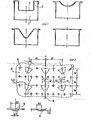
- the conveyor track itself is initially U-shaped and thus trough-shaped in a known manner and adapted to the dimensions of the goods to be conveyed in each case.
- it can also be V-shaped or semicircular, polygonal or in any combination thereof, with the top open, as shown in FIG. 1.
- Known forms of air outlets in the conveyor track floor (2) such as oblique bores, vertical holes and slots are also used.
- the latter are now, according to the invention, not only arranged parallel to the longitudinal axis of the conveyor track as in FIG. 2 in DE - PS 26454464 with the normal to the slot surface 17 there, but at an angle to the latter which can be between 5 and 35 ° depending on the type of material to be conveyed .
- FIG. 2 shows a section of a conveyor floor (2), in which the now oblique slots on both sides of the conveyor track axis (7) are made with, for example, 20 °.
- this alignment causes a second force component perpendicular to it, so that, with a s y m-metric arrangement, this slot on both sides of the longitudinal axis of the conveying path axis (7) is always held in the center of the path, depending on the dimensions of the conveyed material, no guidance through the side walls and does not touch them.
- Slanted slots also have the effect that in the case of piece-like goods with a flat, smooth bottom or only in the conveying direction, continuous furrow-like depressions, and also with flat, smooth side walls, it is possible to dispense with the side walls of a web.
- This oblique arrangement of the slots does not result in a higher air consumption than in the case of an arrangement perpendicular to the conveyor track axis (7) with side guides. If one thinks of conveying goods as diverse as those already mentioned, of plates, boxes, boxes, glass and plastic articles, screws or pencils, then it is understandable that the type and arrangement of such air outlets are of a size and footprint. and must be adapted to the basis weight of the material being conveyed.
- the slot width (4) can be between 3 and 100 mm, the slot height (5) about 0.5 - 3 mm.
- the vertical holes (6), the air outlet of which causes the goods to be lifted, have a diameter of approximately 1-3 mm.
- the necessary air flows through these openings from a channel (1) which, in the case of U-shaped troughs, is arranged at least below the full width of the horizontal conveyor base (2).
- the conveyor track (2) and side walls (3) have a common air duct.
- Such an additional air duct with corresponding air outlets is necessary in curve sections of a conveyor track on the side wall with the larger radius in order to counteract the centrifugal force acting on the conveyed goods.
- the following combinations of the slots are expedient, depending on the material to be conveyed: the normal to the slot surface parallel to the longitudinal axis of the conveyor track (7) or at an angle between 5 and 35 ° to it and slots in the side walls with their normal parallel to the longitudinal axis of the conveyor track ( 7) and, in simpler cases, slots in the specified angular range in the conveyor floor (2) alone, in all cases symmetrical arrangement with the longitudinal axis of the conveyor track (7).
- the former is designed particularly intensively according to the invention in that the track begins with a wide outlet for the conveying air, which extends over the entire track width, in the case of a U-shaped conveyor track over the entire width of the conveyor floor (2). Braking takes place according to the invention in such a way that the number of air in the section of the conveyor track provided for this purpose slots (4,5) in relation to the number of lifting holes (6) is reduced so much that the levitation is maintained, but the speed of the conveyed goods can be reduced to a standstill as desired.
- the open path must be largely closed in these sections in order to prevent the conveyed goods from flying out.
- the covers are provided with an air duct (26) and corresponding and described air outlets, the arrangement of which compresses as the rotary movement progresses, while at the same time it is reduced in the original conveyor floor (20). With a U-shaped trough, the rotation about the longitudinal axis of the conveyor track also gives the side wall coming downward an increasing number of air outlets.
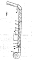
- the fan (8) blows the conveying air into the two channels (12) and (14) of the conveying path (9) separated by a sheet (13), which receives the goods to be conveyed from the chute (10).
- the conveying air enters the conveying path (9) from the upper channel (12) through slots in the conveying floor (11). After the end of the first path section and thus the first air duct (12), the air from the lower duct (14) reaches the conveyor floor (11) in the manifold (15).
- the air volume distribution for both channels (12) and (14) is set with the two throttle valves (16) and (17).
- a storage area is usually provided at the end of a pneumatic conveyor track in order to give the conveyed goods a temporary storage area.
- a speed-controllable fan is used according to the invention, the speed of which is optically or other contactless pulse generator is controlled at the beginning and end of the storage area.
- a vane control can be used. In particular, this keeps the jammed goods floating, since it is difficult and time-consuming to lift them together after the end of the business interruption if they had dropped to the conveyor floor after the fan was switched off.
- the goods have to be stacked after the pneumatic conveyor.
- Such a system is shown in Fig. 4.
- the previous turning device (20-28) is of course not an essential requirement.
- the plates (29) slide into the stacking device (30) as if floating on an air cushion without damage and stack one on top of the other, the lifting cylinder (31) with its plate (32) carrying the plates moving downwards so that each new one arrives Plate (29) of the plate (32) and thus the stack have lowered the thickness of a plate (29).
- the slide (33) is pushed over the stack and a second slide (35) with a vertical pressure plate (36) pushes the stack onto any device for further transport or further processing, such as a shrink packaging system.
- the slide (35, 36) is withdrawn quickly and the plate (32) is quickly moved up again to below the slide (33), which in the meantime has accommodated up to 4 plates. This is withdrawn and the plate (32) takes over these plates and slowly lowers again.
- the movements of the lifting cylinder (31) and the slide (31, 35) are controlled by an optical counting device, not shown.
- the rear wall (37) of the three-sided housing (30) is perforated to allow the air entrained in the conveyor system (1-28) to escape.
- the hose (38) feeds air to the slider housing (34), which, as it emerges to the front, mitigates the impact of the first plate on the advanced slider (33).
Landscapes
- Physics & Mathematics (AREA)
- Engineering & Computer Science (AREA)
- Fluid Mechanics (AREA)
- Mechanical Engineering (AREA)
- Branching, Merging, And Special Transfer Between Conveyors (AREA)
- Stacking Of Articles And Auxiliary Devices (AREA)
- Intermediate Stations On Conveyors (AREA)
Applications Claiming Priority (1)
| Application Number | Priority Date | Filing Date | Title |
|---|---|---|---|
| DE19853512584 DE3512584A1 (de) | 1985-04-06 | 1985-04-06 | Anlage zum pneumatischen schwebefoerdern, stueckartige gueter |
Publications (2)
| Publication Number | Publication Date |
|---|---|
| EP0198518A2 true EP0198518A2 (fr) | 1986-10-22 |
| EP0198518A3 EP0198518A3 (fr) | 1987-06-03 |
Family
ID=6267462
Family Applications (1)
| Application Number | Title | Priority Date | Filing Date |
|---|---|---|---|
| EP86200004A Withdrawn EP0198518A3 (fr) | 1985-04-06 | 1986-01-06 | Dispositif de transport pneumatique à fluidisation pour objets |
Country Status (2)
| Country | Link |
|---|---|
| EP (1) | EP0198518A3 (fr) |
| DE (1) | DE3512584A1 (fr) |
Cited By (2)
| Publication number | Priority date | Publication date | Assignee | Title |
|---|---|---|---|---|
| EP1180486A3 (fr) * | 2000-08-08 | 2002-07-31 | Forschungszentrum Karlsruhe GmbH | Dispositif de transport d'éléments sans contact |
| US7080962B1 (en) | 2005-05-31 | 2006-07-25 | Kimberly-Clark Worldwide, Inc. | Air conveyance apparatus |
Families Citing this family (3)
| Publication number | Priority date | Publication date | Assignee | Title |
|---|---|---|---|---|
| DE3632321C1 (de) * | 1986-09-19 | 1987-12-03 | Otto Feuerfest Gmbh | Verfahren und Vorrichtung zur Herstellung stranggepresster,Hohlraeume aufweisender keramischer Formkoerper |
| DE8708816U1 (de) * | 1987-06-25 | 1988-08-04 | Frank, Gabriele, 6333 Braunfels | Vorrichtung zum pneumatischen Transport |
| DE102014116017A1 (de) * | 2014-11-04 | 2016-05-04 | Lissmac Maschinenbau Gmbh | Vorrichtung mit einer Wendeeinheit zum Wenden eines Werkstücks und Bearbeitungsvorrichtung |
Family Cites Families (22)
| Publication number | Priority date | Publication date | Assignee | Title |
|---|---|---|---|---|
| GB159600A (en) * | 1919-12-01 | 1921-03-01 | Cornelius Edward Kelway | Improvements in apparatus for lifting, hauling, loading, lowering, unloading, and the transmission of power and motion on land and sea |
| US2606483A (en) * | 1949-01-14 | 1952-08-12 | Benner Nawman Inc | Automatic stacking, counting, and transferring apparatus |
| US2849236A (en) * | 1954-09-14 | 1958-08-26 | Kimberly Clark Co | Revolving layboy piler |
| US2805898A (en) * | 1955-01-18 | 1957-09-10 | Jr Edward A Willis | Fluid current conveyor for fragile articles |
| DE1267603B (de) * | 1963-05-22 | 1968-05-02 | Rudolph E Futer | Vorrichtung zum Foerdern festen Foerdergutes in kleiner Form ueber eine Foerderflaeche mit Hilfe von Luftstrahlen |
| BE654693A (fr) * | 1963-10-22 | |||
| DE1291680B (de) * | 1965-05-06 | 1969-03-27 | Tobacco Res And Dev I Ltd | Pneumatische Anlage zum Foerdern plattenfoermiger Gegenstaende |
| GB1161596A (en) * | 1965-10-22 | 1969-08-13 | Pilkington Brothers Ltd | Improvements in or relating to Methods of and Apparatus for Conveying Glass Sheets |
| GB1353741A (en) * | 1970-01-09 | 1974-05-22 | Molins Ltd | Conveyors |
| US3902768A (en) * | 1971-03-17 | 1975-09-02 | Oxy Metal Industries Corp | Vortex diffuser fluid bearing device |
| US3731823A (en) * | 1971-06-01 | 1973-05-08 | Ibm | Wafer transport system |
| CA950853A (en) * | 1972-04-20 | 1974-07-09 | E.B. Eddy Company (The) | Air conveyor |
| US3945505A (en) * | 1974-07-08 | 1976-03-23 | Motorola, Inc. | Indexing apparatus |
| FR2291128A1 (fr) * | 1974-11-15 | 1976-06-11 | Cidelcem | Convoyeur pour le transport d'elements tels que des plateaux contenant des pieces de vaisselle sale |
| DE2509469C3 (de) * | 1975-03-05 | 1980-06-04 | The Motch & Merryweather Machinery Co., Hayward, Calif. (V.St.A.) | Pneumatische Förderanlage |
| FR2348130A1 (fr) * | 1976-04-12 | 1977-11-10 | Monserie Philippe | Convoyeur dynamo-fluidique bidirectionnel |
| DE2645464C2 (de) * | 1976-10-08 | 1982-05-19 | The Motch & Merryweather Machinery Co., Hayward, Calif. | Einrichtung zum unmittelbaren Fördern von leichten Gegenständen in einer Rinne |
| FR2375120A1 (fr) * | 1976-12-24 | 1978-07-21 | Motch Merryweather Machinery | Transporteur pneumatique |
| US4451182A (en) * | 1978-10-02 | 1984-05-29 | Precision Metal Fabricators, Inc. | Air transport system |
| DE8213041U1 (de) * | 1982-05-06 | 1983-02-10 | Helmut Frank Luftkissenförderanlagen, Blechverarbeitung, Maschinenbau, 6331 Bonbaden | Bauelement fuer eine luftkissen-foerderanlage |
| DE3344267A1 (de) * | 1982-10-30 | 1984-06-20 | Hitachi Kiden Kogyo K.K., Amagasaki | Foerderer, insbesondere mit luftkissen und linearmotor |
| US4561806A (en) * | 1983-01-31 | 1985-12-31 | Precision Metal Fabricators, Inc. | Vertical single filer conveyor system |
-
1985
- 1985-04-06 DE DE19853512584 patent/DE3512584A1/de not_active Withdrawn
-
1986
- 1986-01-06 EP EP86200004A patent/EP0198518A3/fr not_active Withdrawn
Cited By (3)
| Publication number | Priority date | Publication date | Assignee | Title |
|---|---|---|---|---|
| EP1180486A3 (fr) * | 2000-08-08 | 2002-07-31 | Forschungszentrum Karlsruhe GmbH | Dispositif de transport d'éléments sans contact |
| US7080962B1 (en) | 2005-05-31 | 2006-07-25 | Kimberly-Clark Worldwide, Inc. | Air conveyance apparatus |
| US7165918B2 (en) | 2005-05-31 | 2007-01-23 | Kimberly-Clark Worldwide, Inc. | Air conveyance system |
Also Published As
| Publication number | Publication date |
|---|---|
| DE3512584A1 (de) | 1986-10-30 |
| EP0198518A3 (fr) | 1987-06-03 |
Similar Documents
| Publication | Publication Date | Title |
|---|---|---|
| DE2541813C2 (de) | Einrichtung zum Ordnen einer Anzahl ungeordnet herangeführter Behälter zu einer einzigen sich fortbewegenden Reihe | |
| DE69908370T2 (de) | Vorrichtung und verfahren zum fördern von gegenständen in form zylindrischer rollen | |
| EP0403901B2 (fr) | Dispositif de tri pour des éléments plats découpés | |
| EP2318293A1 (fr) | Procédé et dispositif de préparation manuelle de commandes de marchandises de détail à l'aide d'une étagère de transfert | |
| EP3248914A1 (fr) | Glissière pour marchandise de détail et procédé d'utilisation d'une telle glissière | |
| DE3920407C2 (fr) | ||
| DE911958C (de) | Vorrichtung zum Stapeln von Briefen und aehnlichen Gegenstaenden | |
| EP3115322A1 (fr) | Procede et dispositif destines a la depalettisation de pneus | |
| AT405640B (de) | Kommissionieranlage | |
| DE4204987C2 (de) | Vorrichtung zum Schneiden und Abstapeln von scheibenförmigen Einzelpackungen | |
| AT507740B1 (de) | Sortiergerät | |
| WO2006108486A1 (fr) | Dispositif de transport comprenant au moins une glissiere pour des articles de detail et procede pour empiler des articles de detail dans un conteneur | |
| EP0198518A2 (fr) | Dispositif de transport pneumatique à fluidisation pour objets | |
| EP3362383B1 (fr) | Dispositif de stockage intermédiaire et procédé de stockage intermédiaire | |
| DE2702724A1 (de) | Einrichtung zum sortieren und ablegen von zuschnitten bei plattenaufteilanlagen | |
| DE3641157A1 (de) | Vorrichtung zum ablegen von boegen auf stapel | |
| DE19515199A1 (de) | Vorrichtung zum Verdrehen von in einem Förderprozeß befindlichen Produkten | |
| DE102019207724A1 (de) | Befördern von traystapeln mit einer denester-einheit | |
| EP2062838B1 (fr) | Méthode et dispositif destinés au retrait de feuilles intermédiaires entre produits palettisés | |
| DE3826638C2 (fr) | ||
| DE20304880U1 (de) | Zwischenspeicher | |
| DE29515627U1 (de) | Kommissionierungsanlage für Apothekenprodukte | |
| DE3624445C2 (fr) | ||
| DE102004001794A1 (de) | Liegewarensorter | |
| EP1462395A1 (fr) | Tampon intermédiaire |
Legal Events
| Date | Code | Title | Description |
|---|---|---|---|
| PUAI | Public reference made under article 153(3) epc to a published international application that has entered the european phase |
Free format text: ORIGINAL CODE: 0009012 |
|
| AK | Designated contracting states |
Kind code of ref document: A2 Designated state(s): AT BE CH DE FR GB IT LI LU NL SE |
|
| PUAL | Search report despatched |
Free format text: ORIGINAL CODE: 0009013 |
|
| RAP1 | Party data changed (applicant data changed or rights of an application transferred) |
Owner name: FA. TOMA |
|
| AK | Designated contracting states |
Kind code of ref document: A3 Designated state(s): AT BE CH DE FR GB IT LI LU NL SE |
|
| 17P | Request for examination filed |
Effective date: 19871111 |
|
| 17Q | First examination report despatched |
Effective date: 19880415 |
|
| STAA | Information on the status of an ep patent application or granted ep patent |
Free format text: STATUS: THE APPLICATION IS DEEMED TO BE WITHDRAWN |
|
| 18D | Application deemed to be withdrawn |
Effective date: 19881026 |
|
| RIN1 | Information on inventor provided before grant (corrected) |
Inventor name: FRANK, HELMUT |