EP0198524A1 - Elektrodenlose Niederdruck-Entladungslampe - Google Patents
Elektrodenlose Niederdruck-Entladungslampe Download PDFInfo
- Publication number
- EP0198524A1 EP0198524A1 EP86200357A EP86200357A EP0198524A1 EP 0198524 A1 EP0198524 A1 EP 0198524A1 EP 86200357 A EP86200357 A EP 86200357A EP 86200357 A EP86200357 A EP 86200357A EP 0198524 A1 EP0198524 A1 EP 0198524A1
- Authority
- EP
- European Patent Office
- Prior art keywords
- lamp
- lead
- lamp vessel
- conductive layer
- metal
- Prior art date
- Legal status (The legal status is an assumption and is not a legal conclusion. Google has not performed a legal analysis and makes no representation as to the accuracy of the status listed.)
- Granted
Links
- 229910052751 metal Inorganic materials 0.000 claims abstract description 25
- 239000002184 metal Substances 0.000 claims abstract description 25
- 239000004020 conductor Substances 0.000 claims abstract description 11
- 239000011521 glass Substances 0.000 claims abstract description 7
- 239000000696 magnetic material Substances 0.000 claims abstract description 7
- 238000004804 winding Methods 0.000 claims abstract description 4
- 210000002105 tongue Anatomy 0.000 claims description 5
- 238000007789 sealing Methods 0.000 description 8
- 238000004519 manufacturing process Methods 0.000 description 4
- RYGMFSIKBFXOCR-UHFFFAOYSA-N Copper Chemical compound [Cu] RYGMFSIKBFXOCR-UHFFFAOYSA-N 0.000 description 3
- OKKJLVBELUTLKV-UHFFFAOYSA-N Methanol Chemical compound OC OKKJLVBELUTLKV-UHFFFAOYSA-N 0.000 description 3
- 210000003298 dental enamel Anatomy 0.000 description 3
- QSHDDOUJBYECFT-UHFFFAOYSA-N mercury Chemical compound [Hg] QSHDDOUJBYECFT-UHFFFAOYSA-N 0.000 description 3
- 229910052753 mercury Inorganic materials 0.000 description 3
- 238000010276 construction Methods 0.000 description 2
- 229910052802 copper Inorganic materials 0.000 description 2
- 239000010949 copper Substances 0.000 description 2
- 230000004927 fusion Effects 0.000 description 2
- 238000007689 inspection Methods 0.000 description 2
- XOLBLPGZBRYERU-UHFFFAOYSA-N tin dioxide Chemical compound O=[Sn]=O XOLBLPGZBRYERU-UHFFFAOYSA-N 0.000 description 2
- 229910001887 tin oxide Inorganic materials 0.000 description 2
- 238000003466 welding Methods 0.000 description 2
- 229910000859 α-Fe Inorganic materials 0.000 description 2
- DDFHBQSCUXNBSA-UHFFFAOYSA-N 5-(5-carboxythiophen-2-yl)thiophene-2-carboxylic acid Chemical compound S1C(C(=O)O)=CC=C1C1=CC=C(C(O)=O)S1 DDFHBQSCUXNBSA-UHFFFAOYSA-N 0.000 description 1
- 229910052693 Europium Inorganic materials 0.000 description 1
- 229910052771 Terbium Inorganic materials 0.000 description 1
- UPHIPHFJVNKLMR-UHFFFAOYSA-N chromium iron Chemical compound [Cr].[Fe] UPHIPHFJVNKLMR-UHFFFAOYSA-N 0.000 description 1
- 230000000694 effects Effects 0.000 description 1
- 230000005684 electric field Effects 0.000 description 1
- OGPBJKLSAFTDLK-UHFFFAOYSA-N europium atom Chemical compound [Eu] OGPBJKLSAFTDLK-UHFFFAOYSA-N 0.000 description 1
- 230000002349 favourable effect Effects 0.000 description 1
- 230000004907 flux Effects 0.000 description 1
- 238000007499 fusion processing Methods 0.000 description 1
- 239000003292 glue Substances 0.000 description 1
- 229910052743 krypton Inorganic materials 0.000 description 1
- DNNSSWSSYDEUBZ-UHFFFAOYSA-N krypton atom Chemical compound [Kr] DNNSSWSSYDEUBZ-UHFFFAOYSA-N 0.000 description 1
- 239000000203 mixture Substances 0.000 description 1
- SIWVEOZUMHYXCS-UHFFFAOYSA-N oxo(oxoyttriooxy)yttrium Chemical compound O=[Y]O[Y]=O SIWVEOZUMHYXCS-UHFFFAOYSA-N 0.000 description 1
- 239000003566 sealing material Substances 0.000 description 1
- 238000005507 spraying Methods 0.000 description 1
- 229920002994 synthetic fiber Polymers 0.000 description 1
- -1 terbium-activated cerium magnesium aluminate Chemical class 0.000 description 1
- HPGGPRDJHPYFRM-UHFFFAOYSA-J tin(iv) chloride Chemical compound Cl[Sn](Cl)(Cl)Cl HPGGPRDJHPYFRM-UHFFFAOYSA-J 0.000 description 1
Images

Classifications
-
- H—ELECTRICITY
- H01—ELECTRIC ELEMENTS
- H01J—ELECTRIC DISCHARGE TUBES OR DISCHARGE LAMPS
- H01J65/00—Lamps without any electrode inside the vessel; Lamps with at least one main electrode outside the vessel
- H01J65/04—Lamps in which a gas filling is excited to luminesce by an external electromagnetic field or by external corpuscular radiation, e.g. for indicating plasma display panels
- H01J65/042—Lamps in which a gas filling is excited to luminesce by an external electromagnetic field or by external corpuscular radiation, e.g. for indicating plasma display panels by an external electromagnetic field
- H01J65/048—Lamps in which a gas filling is excited to luminesce by an external electromagnetic field or by external corpuscular radiation, e.g. for indicating plasma display panels by an external electromagnetic field the field being produced by using an excitation coil
Definitions
- the invention relates to an electrodeless low-pressure discharge lamp comprising a glass lamp vessel which is sealed in a gas-tight manner and is filled with a metal vapour and a rare gas, the wall of the lamp vessel being provided with a tubular protuberance which accommodates a rod-shaped core of magnetic material surrounded by a wire winding connected to a high-frequency supply unit, by means of which during operation of the lamp an electrical discharge is maintained in the lamp vessel, the inner wall surface of the lamp vessel being provided with a transparent conductive layer which is electrically connected by means of a lead-through member to a conductor located outside the lamp vessel.
- a lamp is known from Netherlands Patent Application No. 8205025 laid open to public inspection.
- the transparent conductive layer is connected during operation of the lamp via a conductor connected to the lamp cap to one of the lead-in wires of the supply mains.
- the lamp vessel ofthe known lamp is sealed in a gas-tight manner by means of sealing material (such as glass enamel) by a sealing member which is provided with the tubular protuberance for receiving the core of magnetic material.
- the lead-through member for the connection ofthe transparent conductive layer to the conductor located outside the lamp vessel consist of a metal plate which is bent into the shape of a U and is secured around an edge of the lamp vessel prior to sealing of the sealing member and consequently extends through the seal.
- the invention has for its object to provide an electrodeless low-pressure discharge lamp, in which the connection between the transparent conductive layer on the inner side ofthe lamp vessel and a conductor located outside the lamp vessel can be established in a simple, reliable and quick manner.
- this object is achieved in an electrodeless discharge lamp of the kind mentioned in the opening paragraph in that the lead-through member is located in the wall at the end of the tubular protuberance, the lead-through member being electrically connected to the internal conductive layer.
- the lamp according to the invention can be manufactured in a simple manner. The use of small separate parts is avoided. Another great advantage of the lamp is that the use of glass enamel is not necessary for sealing the lamp vessel in a gas-tight manner.
- the sealing member is sealed by a simple fusion process, which has a great favourable influence on the speed of the manufacturing process.
- the lead-through member (consisting, for example, of a metal pin, wire or sleeve) at the end of the tubular protuberance further has the advantage that the lamp can be sufficiently safely touched.
- the lead-through member is in fact connected during operation of the lamp to one of the conductors of the supply mains.
- the lead-through member is arranged in the pinch of a mount closing the tubular protuberance.
- the electrical connection between the lead- through member and the conductive transparent layer is established, for example, by welding a metal wire both to the said member and to the layer, for example with the use of a laser beam.
- a connection is preferred, in which the lead-through member has secured to it a metal wire spring, whose end presses against the said conductive layer.
- An electrical connection is then established.
- Such a construction is very suitable to be used in a mass production process.
- First the sealing member with protuberance is provided with the lead-through member with wire spring, whereupon the lamp vessel (with transparent conductive layer) is sealed in a gas-tight manner by fusion with the sealing member.
- the lead-through member has secured to it a number of metal resilient tongues, whose ends press against the internal conductive layer.
- the electrical connection with the conductive layer is established at several areas at a time.
- the said tongues are in the shape of longitudinal strips and are formed, for example, from a thin-walled metal conical body, whose tip is connected to the lead-through member. Such a body can be manufactured in a simple manner.
- the lead-through member is electrically connected to the said metal body, the magnetic core being provided with a recess extending throughout its length and inwardly as far as the metal body.
- This embodiment has the advantage that the said rod-shaped metal body in the core serves not only to dissipate heat, but at the same time serves as an electrical conductor.
- the magnetic core is provided with the said axially extending recess.
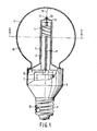
- the lamp shown in Fig. 1 comprises a glass lamp vessel 1 which is sealed in a gas-tight manner and is filled with a quantity of mercury and a rare gas, such as krypton (at a pressure of about 70 Pa).
- the wall of the lamp vessel is provided with a tubular protuberance 2, which accommodates a rod-shaped core 3 of magnetic material (ferrite).
- the core 3 is surrounded by a winding 4 consisting of a number of turns of copper wire, which is connected through wires 5, 6 to a high-frequency supply unit located in a metal housing 7.
- a high-frequency magnetic field is produced in the core, while an electric field is produced in the lamp vessel.
- the housing 7 is surrounded by a space bounded by a wall portion 8 of synthetic material which is slightly conical at one side and is secured on the lower side of the lamp vessel.
- the said wall portion 8 is provided at its end with an Edison lamp cap 9.
- the inner side of the lamp vessel is provided with a transparent conductive layer 10, which consists of fluorine-doped tin oxide.
- a luminescent layer (not shown in the drawing).
- the said internal conductive layer is connected to one of the lead-in wires of the supply mains in order to suppress interference currents at the conductors of the supply mains.
- Use is then made of a heat-conducting copper rod 11 which is present in the magnetic core 3 and is connected at one end to a metal pin- shaped lead-through member 12.
- This lead-through member 12 is located at the end of the tubular protuberance 2. It is accommodated in the pinch 13 of a mount 14, which is secured to the end of the tubular protuberance 2.
- the lead-through member is electrically connected to the inernal conductive layer 10 by a metal wire spring 15.
- the free resilient end of this spring 15 bears on the internal conductive layer 10.
- the other end of the rod 11 is connected via the wire 16 to the Edison cap 9, by means of which the connection with the supply mains is established,
- the sealing member provided with the protuberance 2 with the lead-through member 12, the spring 15 and the core 3 with the rod 11 which is secured to the wall of protuberance 2 by a suitable glue is arranged and these parts are interconnected in a gas-tight manner by a simple fusion of the edges.
- the luminescent layer is locally removed by the free end of the spring and a sufficient contact with the internal conductive layer is formed.
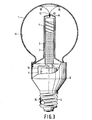
- the magnetic core 3 is provided throughout its length with a recess 17 extending inwardly of the core as far as the rod 11 in order to keep the impedance of the rod during operation as low as possible. This is illustrated in Fig. 2.
- the central part of the magnet core 3 is not provided with a conductive copper rod.
- the lead-through member 12 is connected by a metal conductor 16 directly to the lamp cap 9.
- the lead-through member is provided with a number (for example eight) of resilient metal tongues 18, (two of which are visible in Fig. 3) whose ends 19 bear on the internal conductive layer. A reliable contact with the said layer is then possible.
- the tongues 18, consisting of chromium iron which is resistant to the effect of the discharge are in the shape of longitudinal strips and are secured to the leadthrough 12 by welding.
- the largest diameter of the bulb-shaped lamp vessel 1 is about 65 mm and the length of the lamp vessel is about 70 mm.
- the magnetic core (length 50 mm, diameter 8 mm) consists of a suitable ferrite (Philips 4C6).
- the supply unit in the metal housing 7 (which is likewise connected to the wire 16) comprises a high-frequency oscillator having a frequency of 2.65 MHz (see USP 4,415,838).
- the transparent conductive layer 10 (Re about 20 ⁇ ) of fluorine-doped tin oxide is applied by spraying a solution comprising tin chloride and a small quantity of ammonium fluoride in methanol.
- the luminescent layer applied thereto comprises a mixture of phosphors consisting of green luminescing terbium-activated cerium magnesium aluminate and red luminescing yttrium oxide activated by trivalent europium. It has been measured that with a power of 17 W supplied to the lamp (inclusive of feeding) the luminous flux was about 1200 lumen. The measured decrease of the interference current in the supply mains was + 50 dB( / uV).
Landscapes
- Physics & Mathematics (AREA)
- Electromagnetism (AREA)
- Engineering & Computer Science (AREA)
- Plasma & Fusion (AREA)
- Discharge Lamps And Accessories Thereof (AREA)
Applications Claiming Priority (2)
| Application Number | Priority Date | Filing Date | Title |
|---|---|---|---|
| NL8500738 | 1985-03-14 | ||
| NL8500738A NL8500738A (nl) | 1985-03-14 | 1985-03-14 | Elektrodeloze lagedrukontladingslamp. |
Publications (2)
| Publication Number | Publication Date |
|---|---|
| EP0198524A1 true EP0198524A1 (de) | 1986-10-22 |
| EP0198524B1 EP0198524B1 (de) | 1990-10-10 |
Family
ID=19845684
Family Applications (1)
| Application Number | Title | Priority Date | Filing Date |
|---|---|---|---|
| EP86200357A Expired - Lifetime EP0198524B1 (de) | 1985-03-14 | 1986-03-07 | Elektrodenlose Niederdruck-Entladungslampe |
Country Status (5)
| Country | Link |
|---|---|
| US (1) | US4728867A (de) |
| EP (1) | EP0198524B1 (de) |
| JP (1) | JPH0719581B2 (de) |
| DE (1) | DE3674826D1 (de) |
| NL (1) | NL8500738A (de) |
Cited By (1)
| Publication number | Priority date | Publication date | Assignee | Title |
|---|---|---|---|---|
| EP0668605A3 (de) * | 1994-02-17 | 1997-03-26 | Tungsram Reszvenytarsasag | Elektrodenlose Niederdruckentladungslampe. |
Families Citing this family (20)
| Publication number | Priority date | Publication date | Assignee | Title |
|---|---|---|---|---|
| US4927217A (en) * | 1987-06-26 | 1990-05-22 | U.S. Philips Corp. | Electrodeless low-pressure discharge lamp |
| NL8900406A (nl) * | 1989-02-20 | 1990-09-17 | Philips Nv | Elektrodeloze lagedrukontladingslamp. |
| US5397966A (en) * | 1992-05-20 | 1995-03-14 | Diablo Research Corporation | Radio frequency interference reduction arrangements for electrodeless discharge lamps |
| US5581157A (en) * | 1992-05-20 | 1996-12-03 | Diablo Research Corporation | Discharge lamps and methods for making discharge lamps |
| US5306986A (en) * | 1992-05-20 | 1994-04-26 | Diablo Research Corporation | Zero-voltage complementary switching high efficiency class D amplifier |
| TW214598B (en) * | 1992-05-20 | 1993-10-11 | Diablo Res Corp | Impedance matching and filter network for use with electrodeless discharge lamp |
| TW210397B (en) * | 1992-06-05 | 1993-08-01 | Diablo Res Corp | Base mechanism to attach an electrodeless discharge light bulb to a socket in a standard lamp harp structure |
| AU4245193A (en) * | 1992-06-05 | 1994-01-04 | Diablo Research Corporation | Electrodeless discharge lamp containing push-pull class e amplifier and bifilar coil |
| US5572083A (en) * | 1992-07-03 | 1996-11-05 | U.S. Philips Corporation | Electroless low-pressure discharge lamp |
| US5434482A (en) * | 1993-10-04 | 1995-07-18 | General Electric Company | Electrodeless fluorescent lamp with optimized amalgam positioning |
| US5500567A (en) * | 1994-02-10 | 1996-03-19 | General Electric Company | Apparatus for securing an amalgam at the apex of an electrodeless fluorescent lamp |
| US5446350A (en) * | 1994-04-18 | 1995-08-29 | General Electric Company | Impedance matching circuit for an electrodeless fluorescent lamp ballast |
| CA2145894A1 (en) * | 1994-04-18 | 1995-10-19 | Louis R. Nerone | External metallization configuration for an electrodeless fluorescent lamp |
| US5559392A (en) * | 1994-06-13 | 1996-09-24 | General Electric Company | Apparatus for securing an amalgam at the apex of an electrodeless fluorescent lamp |
| EP0731778B1 (de) * | 1994-09-14 | 2000-05-03 | Koninklijke Philips Electronics N.V. | Gesinterter formkörper, transformer-kern und induktor aus li(ni)zn-ferrite material sowie anwendungen davon |
| WO1996037908A1 (en) * | 1995-05-24 | 1996-11-28 | Philips Electronics N.V. | Lighting unit and electrodeless low-pressure discharge lamp, and discharge vessel for use in said lighting unit |
| US5702179A (en) * | 1995-10-02 | 1997-12-30 | Osram Sylvania, Inc. | Discharge lamp having light-transmissive conductive coating for RF containment and heating |
| US6653783B2 (en) * | 2000-09-26 | 2003-11-25 | Matsushita Electric Industrial Co., Ltd. | Self-ballasted electrodeless discharge lamp with startability improving means |
| DE10058852A1 (de) * | 2000-11-27 | 2002-06-06 | Raylux Gmbh | Kompakte elektrodenlose Niederdruck-Gasentladungslampe mit erhöhter Lebensdauer |
| US20090153016A1 (en) * | 2007-12-17 | 2009-06-18 | General Electric Company | Colored fluorescent lamp |
Citations (1)
| Publication number | Priority date | Publication date | Assignee | Title |
|---|---|---|---|---|
| EP0074690A2 (de) * | 1981-09-14 | 1983-03-23 | Koninklijke Philips Electronics N.V. | Elektrodelose Gasentladungslampe |
Family Cites Families (3)
| Publication number | Priority date | Publication date | Assignee | Title |
|---|---|---|---|---|
| US3521120A (en) * | 1968-03-20 | 1970-07-21 | Gen Electric | High frequency electrodeless fluorescent lamp assembly |
| US3924223A (en) * | 1974-02-21 | 1975-12-02 | Westinghouse Electric Corp | Power line communication system having a protective terminating impedance arrangement |
| JPS534382A (en) * | 1976-07-02 | 1978-01-14 | Toshiba Corp | High frequency illuminator |
-
1985
- 1985-03-14 NL NL8500738A patent/NL8500738A/nl not_active Application Discontinuation
-
1986
- 1986-03-07 DE DE8686200357T patent/DE3674826D1/de not_active Expired - Lifetime
- 1986-03-07 EP EP86200357A patent/EP0198524B1/de not_active Expired - Lifetime
- 1986-03-10 US US06/838,222 patent/US4728867A/en not_active Expired - Fee Related
- 1986-03-11 JP JP61051583A patent/JPH0719581B2/ja not_active Expired - Lifetime
Patent Citations (1)
| Publication number | Priority date | Publication date | Assignee | Title |
|---|---|---|---|---|
| EP0074690A2 (de) * | 1981-09-14 | 1983-03-23 | Koninklijke Philips Electronics N.V. | Elektrodelose Gasentladungslampe |
Non-Patent Citations (1)
| Title |
|---|
| PATENT ABSTRACTS OF JAPAN, vol. 2, no. 47, 29th March 1978, page 184 (M-78); & JP-A-53 004 382 (TOKYO SHIBAURA DENKI K.K.) 14-01-1978 * |
Cited By (1)
| Publication number | Priority date | Publication date | Assignee | Title |
|---|---|---|---|---|
| EP0668605A3 (de) * | 1994-02-17 | 1997-03-26 | Tungsram Reszvenytarsasag | Elektrodenlose Niederdruckentladungslampe. |
Also Published As
| Publication number | Publication date |
|---|---|
| JPS61214350A (ja) | 1986-09-24 |
| EP0198524B1 (de) | 1990-10-10 |
| DE3674826D1 (de) | 1990-11-15 |
| NL8500738A (nl) | 1986-10-01 |
| US4728867A (en) | 1988-03-01 |
| JPH0719581B2 (ja) | 1995-03-06 |
Similar Documents
| Publication | Publication Date | Title |
|---|---|---|
| EP0198524B1 (de) | Elektrodenlose Niederdruck-Entladungslampe | |
| US4727294A (en) | Electrodeless low-pressure discharge lamp | |
| EP0162504B1 (de) | Elektrodenlose Niederdruckentladungslampe | |
| US4568859A (en) | Discharge lamp with interference shielding | |
| US4727295A (en) | Electrodeless low-pressure discharge lamp | |
| EP0294004B1 (de) | Elektrodenlose Niederdruckentladungslampe | |
| US4645967A (en) | Electrodeless low-pressure gas discharge lamp | |
| EP0074690B1 (de) | Elektrodelose Gasentladungslampe | |
| EP0332263B1 (de) | Elektrodenlose Niederdruckentladungslampe | |
| US4422017A (en) | Electrodeless gas discharge lamp | |
| EP0252546B1 (de) | Elektrodenlose Niederdruck-Entladungslampe | |
| US4661746A (en) | Electrodeless low-pressure discharge lamp | |
| US4445069A (en) | Low-pressure discharge lamp | |
| EP0772886A1 (de) | Beleuchtungseinheit und elektrodenlose niederdruckentladungslampe, und entladungsgefäss zur verwendung in einer solchen beleuchtungseinheit | |
| CA2354617C (en) | Discharge lamp | |
| CN1003829B (zh) | 无电极低压放电灯 |
Legal Events
| Date | Code | Title | Description |
|---|---|---|---|
| PUAI | Public reference made under article 153(3) epc to a published international application that has entered the european phase |
Free format text: ORIGINAL CODE: 0009012 |
|
| AK | Designated contracting states |
Kind code of ref document: A1 Designated state(s): BE DE FR GB NL |
|
| 17P | Request for examination filed |
Effective date: 19870417 |
|
| 17Q | First examination report despatched |
Effective date: 19880720 |
|
| GRAA | (expected) grant |
Free format text: ORIGINAL CODE: 0009210 |
|
| AK | Designated contracting states |
Kind code of ref document: B1 Designated state(s): BE DE FR GB NL |
|
| REF | Corresponds to: |
Ref document number: 3674826 Country of ref document: DE Date of ref document: 19901115 |
|
| ET | Fr: translation filed | ||
| PLBE | No opposition filed within time limit |
Free format text: ORIGINAL CODE: 0009261 |
|
| STAA | Information on the status of an ep patent application or granted ep patent |
Free format text: STATUS: NO OPPOSITION FILED WITHIN TIME LIMIT |
|
| PG25 | Lapsed in a contracting state [announced via postgrant information from national office to epo] |
Ref country code: NL Effective date: 19911001 |
|
| 26N | No opposition filed | ||
| NLV4 | Nl: lapsed or anulled due to non-payment of the annual fee | ||
| PGFP | Annual fee paid to national office [announced via postgrant information from national office to epo] |
Ref country code: BE Payment date: 19950307 Year of fee payment: 10 |
|
| REG | Reference to a national code |
Ref country code: FR Ref legal event code: CD |
|
| PGFP | Annual fee paid to national office [announced via postgrant information from national office to epo] |
Ref country code: GB Payment date: 19960229 Year of fee payment: 11 |
|
| PGFP | Annual fee paid to national office [announced via postgrant information from national office to epo] |
Ref country code: FR Payment date: 19960327 Year of fee payment: 11 |
|
| PG25 | Lapsed in a contracting state [announced via postgrant information from national office to epo] |
Ref country code: BE Effective date: 19960331 |
|
| PGFP | Annual fee paid to national office [announced via postgrant information from national office to epo] |
Ref country code: DE Payment date: 19960523 Year of fee payment: 11 |
|
| BERE | Be: lapsed |
Owner name: PHILIPS ELECTRONICS N.V. Effective date: 19960331 |
|
| PG25 | Lapsed in a contracting state [announced via postgrant information from national office to epo] |
Ref country code: GB Effective date: 19970307 |
|
| GBPC | Gb: european patent ceased through non-payment of renewal fee |
Effective date: 19970307 |
|
| PG25 | Lapsed in a contracting state [announced via postgrant information from national office to epo] |
Ref country code: FR Free format text: LAPSE BECAUSE OF NON-PAYMENT OF DUE FEES Effective date: 19971128 |
|
| PG25 | Lapsed in a contracting state [announced via postgrant information from national office to epo] |
Ref country code: DE Effective date: 19971202 |
|
| REG | Reference to a national code |
Ref country code: FR Ref legal event code: ST |