EP0198576A2 - Eingabevorrichtung für elektronische Uhr - Google Patents
Eingabevorrichtung für elektronische Uhr Download PDFInfo
- Publication number
- EP0198576A2 EP0198576A2 EP86300999A EP86300999A EP0198576A2 EP 0198576 A2 EP0198576 A2 EP 0198576A2 EP 86300999 A EP86300999 A EP 86300999A EP 86300999 A EP86300999 A EP 86300999A EP 0198576 A2 EP0198576 A2 EP 0198576A2
- Authority
- EP
- European Patent Office
- Prior art keywords
- indicia
- timepiece
- switch
- carrying member
- pattern
- Prior art date
- Legal status (The legal status is an assumption and is not a legal conclusion. Google has not performed a legal analysis and makes no representation as to the accuracy of the status listed.)
- Granted
Links
- 230000001788 irregular Effects 0.000 claims description 5
- 238000001514 detection method Methods 0.000 description 3
- 230000000694 effects Effects 0.000 description 2
- 238000012856 packing Methods 0.000 description 2
- 210000001072 colon Anatomy 0.000 description 1
- 230000006870 function Effects 0.000 description 1
- 239000011521 glass Substances 0.000 description 1
- 238000005070 sampling Methods 0.000 description 1
- 230000001360 synchronised effect Effects 0.000 description 1
- 230000007704 transition Effects 0.000 description 1
- XLYOFNOQVPJJNP-UHFFFAOYSA-N water Substances O XLYOFNOQVPJJNP-UHFFFAOYSA-N 0.000 description 1
Images


Classifications
-
- G—PHYSICS
- G04—HOROLOGY
- G04C—ELECTROMECHANICAL CLOCKS OR WATCHES
- G04C3/00—Electromechanical clocks or watches independent of other time-pieces and in which the movement is maintained by electric means
- G04C3/001—Electromechanical switches for setting or display
- G04C3/005—Multiple switches
Definitions
- the present invention relates to an electronic timepiece.
- An electronic watch is known from US-A-4,451,159 having a rotatable annular dial marked with indicia, the dial having projections and recesses which cause switch pins to move up and down, so that the switch is turned ON/OFF, as the dial is rotated.
- the maximum number of modes in which the watch could be used depended upon the number of switch pins and was restricted to the ability to determine the angular position of the annular dial. For example, when there were four switch pins, the mechanism could be used in only up to 12 modes at the maximum. Generally if the number of switch pins is n, the maximum number of modes will be n x (n-1) if n S 3. However, the number of switch pins was limited to four, and it was actually impossible to increase the number of switch pins. Moreover, as the switch pins were moved up and down by the projections and recesses of the dial, it was impossible in practice to provide more than 12 projections and recesses. Therefore, it was impossible to provide more than 12 modes.
- an electronic timepiece on whose case there is mounted an indicia-carrying member which may be moved relatively to the case so as to bring a selected indicium on the indicia-carrying member to a predetermined indicating position, an electrical circuit comprising a plurality of switch pins engageable with the indicia-carrying member or means secured thereto, and an electronic device, controlled by said electrical circuit, responsive to the position of the indicia-carrying member, characterised in that the indicia-carrying member or means secured thereto has a pattern of electrically conductive and non-conductive areas over which the switch pins pass when the indicia-carrying member is moved over the case, at least one portion of said pattern having a shape which differs from that of the other portions thereof so that, when a switch pin is in contact with said one portion, the electrical signals which are sent to the electronic device can be distinguished thereby from the electrical signals which are sent thereto when there is no switch pin in contact
- the indicia-carrying member or the means secured thereto has a plurality of projections each of which is provided with a respective conductive area.
- One of the said projections is preferably larger than the others.
- the indicia-carrying member may be rotatably mounted on the case, the conductive areas being angularly spaced apart.
- Resilient means may be provided for urging the switch pins into engagement with the said pattern.
- the electronic device is arranged to memorise the position of the indicia-carrying member on the case and its direction of movement over the latter.
- first memory circuit for memorising existing switch data
- second memory circuit for memorising previous switch data
- output means for outputting to said electronic device electrical signals from said first and second memory circuits which are representative of said position and direction.
- setting means for setting said electronic device to a particular value by means of a switching signal which is produced when a switch pin engages the said one portion.
- the electronic device preferably comprises an up-down counter.
- Each of the first and second memory circuits preferably includes a flip-flop.
- switching may be effected by contact between an electrical pattern formed directly on an annular dial (or means secured thereto) and switch pins. Consequently ON/OFF operation is not effected by up and down movement of the switch pins. Moreover, switching may be effected without employing projections and recesses on the annular dial and, instead, providing an electrical pattern on the annular dial.
- the present invention enables the electronic timepiece to have at least 60 modes as a result of the provision of an electrical pattern on the annular dial, this being in contrast to the maximum of 12 modes in the case of the known timepiece. Moreover, only three switch pins are necessary and the position of the switch pins can be established more easily than in the case of the known timepiece.
- the timepiece of the present invention may have means for avoiding mis-detection of the direction of rotation and the rotational position of the annular dial, this being achieved by providing three positions where the ON/OFF operation of the three switch pins and the position of the annular dial correspond exactly. In this case, even when mis-detection does occur and the value shown by the said up-down counter does not correspond to the position of the annular dial, the position of the annular dial is made to coincide with the value of the said counter when the annular dial passes over one of the three positions.
- Figure 1 is a plan view of an electronic timepiece according to the present invention, the timepiece being used as a memo watch.
- the timepiece is provided with an annular dial 1 on which there are marked forty-eight equi-angularly spaced apart characters or indicia 6 which are constituted by the numbers 0-9; the letters A-Z; bracket, addition, subtraction, multiplication, division and equals signs; and a colon, full stop, comma and query sign.
- Sufficient characters are thus provided to enable them to be used for the taking of notes.
- a user wants to take a note or memo, he can rotate the annular dial and set it successively to the desired characters 6 so as to input a memo.
- FIG 2 is a sectional view of the memo watch of Figure 1.
- the annular dial 1 is mounted on an outer case 2 of the watch which is provided with the button switches 3 and the display portion 4.
- the button switches 3 may also be used to adjust the indication provided by the display portion 4.
- the watch is made water-resistant by a packing 10 which is interposed between the annular dial 1 and a glass 11, and by a further packing 10awhich is interposed between a rear case 15 and the outer case 2.
- a panel frame 12 is provided with three electrically conductive switch pins 8 (only one of which is shown in Figure 2), each switch pin 8 being always urged by a respective electrically conductive spring 9 with a certain force towards an electrically conductive patterned member 7 carried by the annular dial 1.
- the patterned member 7 has a pattern of electrically conductive and non-conductive areas over which the switch pins 8 pass when the annular dial 1 is rotated. Each conductive area is provided on a radially inwardly extending projection 7 of the patterned member 7. Each spring 9 presses with a certain pressure against a circuit pattern 16 mounted on a circuit base plate 17, whereby the springs 9 serve as electrical paths between the switch pins 8 and the circuit pattern 16.
- the circuit base plate 17 is mounted on a battery housing 14 which contains an electric battery 13.
- Figure 3 is a view of the patterned member 7 provided on the annular dial 1, as seen from above.
- Figure 3 shows the positions of the three switch pins which are shown as switch pins 8a, 8b, 8cand are also referred to below as switch pins A, B, C respectively.
- Switch pins A, B, C i.e. 8a, 8b, 8c
- the annular dial 1 shown in Figure 3 is at the position (0) in which the character 0 is aligned with the index mark 5.
- Numeral 7a indicates a position where the patterned member 7 has an irregular projection. That is to say, the projection 7a extends through the angular spaces occupied by two characters (i.e. the characters "3" and "4") whereas each of the other projections T extends through a single such angular space.
- the ON/OFF states of the three switch pins A to C (8a to 8c) depends upon the position of the annular dial 1.
- the annular dial 1 is divided into forty-eight parts, but if there are three switch pins, it may be divided into any multiple of 3. Also, the switch pins A to C (8a to 8c) need not be disposed at the positions shown in Figure 3, since they can, for example, be provided at any angular position which is spaced by any multiple of 22.5 degrees from the points shown in Figure 3.
- Figure 4 is a table relating to the various positions of the annular dial 1 and the corresponding ON/OFF state of the switch pins A to C (8a to 8 g ).
- the switch pins 8a, 8b, 8c are out of contact with the irregular projection 7a, one of the three switches is always ON.
- the annular dial 1 is then rotated through one "click” (i.e. through 7.5 degrees), one of the two switches that were OFF turns ON, and the switch which was ON turns OFF.
- the direction of rotation i.e. whether to the "right” (clockwise) or to the "left” (counterclockwise), can be determined by the input circuit which is described below.
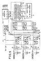
- the input circuit 20 shown in Figure 5 the . switches A to C operate as in Figure 4.
- the input circuit 20 ensures that the value shown by the counter 21 coincides with the position of the annular dial 1 by detecting the direction of rotation and the angular position of the annular dial 1.
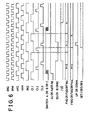
- a clock generator 22 shown in Figure 5 always outputs signals CLI to CL3 as shown in Figure 6, when setting the sampling frequency of switches A to C to 2KHz.
- the 48 step up-down counter 21 shown in Figure 5 is a counter wherein, when one pulse of active high level is inputted either to its up terminal or to its down terminal, the value of the counter is adjusted by + 1 or -1, and when the terminals SET 1, SET 5,•SET 9 are at high level, the content of the counter 21 is respectively set to 1, 5, 9.
- F1, F2 are T (trigger) type flip-flops
- F4 to F15 are D (data) type flip-flops, both operating when terminal T or terminal C receives an active low level signal.
- the present data (n) latched at the flip-flops F10, F12, F14 and the former data (n-1) latched at the flip-flops F11, F13, F15 are decoded by a decoding circuit composed of NAND gates 87 to B9, CO to C7, and then the UP or DOWN signal is outputted to the 48 step up-down counter 21 at the timing of CL3.
- a decoding circuit composed of NAND gates 87 to B9, CO to C7
- the UP DOWN signal is not outputted.
- the flip-flops F1, F2 are always reset by the output of a NAND gate B3 through a NOR-gate DO and is set. to output CL1 to CL3. This is to detect which one of the switches A to C turns on, that is to detect the transition of 1 (on, on, off), 0 (on, off, off) 5 (off, on, on), 4 (off, on, off), or 9 (on, off, on), 8 (off, off, on), by resetting the R-S latch composed of the NAND gates A4 to A9, at CL1.
- the switch input circuit shown in Figure 5 detects the ON/OFF operation of the switches A to C, and is possible to make the position of the annular dial 1 coincide with the value of the 48 step up-down counter 21.
- the electronic timepiece of the present invention may have a larger number of modes than known devices, the annular dial 1 being usable for purposes other than time information modes.
- the electronic timepiece of the present invention can be utilized for character-letter selection of memo watches as shown in Figure 1, or for the data input of alarm time in the case of watches having only usual functions.
- the electronic timepiece of the present invention can easily be made in a large number of different designs.
Landscapes
- Physics & Mathematics (AREA)
- General Physics & Mathematics (AREA)
- Electric Clocks (AREA)
- Rotary Switch, Piano Key Switch, And Lever Switch (AREA)
Applications Claiming Priority (2)
| Application Number | Priority Date | Filing Date | Title |
|---|---|---|---|
| JP26881/85 | 1985-02-14 | ||
| JP60026881A JPH0648299B2 (ja) | 1985-02-14 | 1985-02-14 | 電子時計用回転スイッチ |
Publications (3)
| Publication Number | Publication Date |
|---|---|
| EP0198576A2 true EP0198576A2 (de) | 1986-10-22 |
| EP0198576A3 EP0198576A3 (en) | 1987-04-08 |
| EP0198576B1 EP0198576B1 (de) | 1990-01-10 |
Family
ID=12205621
Family Applications (1)
| Application Number | Title | Priority Date | Filing Date |
|---|---|---|---|
| EP86300999A Expired EP0198576B1 (de) | 1985-02-14 | 1986-02-13 | Eingabevorrichtung für elektronische Uhr |
Country Status (4)
| Country | Link |
|---|---|
| US (1) | US4678344A (de) |
| EP (1) | EP0198576B1 (de) |
| JP (1) | JPH0648299B2 (de) |
| DE (1) | DE3668245D1 (de) |
Cited By (4)
| Publication number | Priority date | Publication date | Assignee | Title |
|---|---|---|---|---|
| CH685273GA3 (de) * | 1992-10-05 | 1995-05-31 | Andreas Tschannen Henri Cosand | Uhr, insbesondere Armbanduhr. |
| EP0710899A1 (de) * | 1994-11-03 | 1996-05-08 | Asulab S.A. | Uhr mit Zeitangabe durch nicht hörbare Schwingungen |
| GB2350523A (en) * | 1999-05-26 | 2000-11-29 | Nokia Mobile Phones Ltd | Radio communication device |
| EP0974879B1 (de) * | 1997-11-19 | 2007-07-25 | Seiko Epson Corporation | Datenverarbeitungsvorrichtung |
Families Citing this family (8)
| Publication number | Priority date | Publication date | Assignee | Title |
|---|---|---|---|---|
| US5933391A (en) * | 1997-07-18 | 1999-08-03 | Lux Products Corporation | Timer |
| FR2777363B1 (fr) * | 1998-04-14 | 2000-06-16 | Philips Frederic | Montre a dispositif de conversion |
| JP3627531B2 (ja) * | 1998-09-30 | 2005-03-09 | セイコーエプソン株式会社 | 情報処理装置 |
| US6879863B2 (en) * | 2003-04-09 | 2005-04-12 | Kohler Co. | User interface for controlling a whirlpool tub |
| FI118950B (fi) * | 2003-07-04 | 2008-05-30 | Polar Electro Oy | Mekaaninen mittalaite ja mittausmenetelmä |
| KR102353456B1 (ko) | 2015-05-07 | 2022-01-21 | 삼성전자주식회사 | 회전 인식 장치 및 그를 구비하는 전자 장치 |
| TWM516175U (zh) * | 2015-07-23 | 2016-01-21 | 廣達電腦股份有限公司 | 智慧型手錶 |
| KR102821845B1 (ko) * | 2019-11-22 | 2025-06-17 | 삼성전자주식회사 | 생체 신호 획득을 위한 생체 센서 및 전극을 포함하는 전자 장치 |
Family Cites Families (11)
| Publication number | Priority date | Publication date | Assignee | Title |
|---|---|---|---|---|
| US3884033A (en) * | 1973-10-17 | 1975-05-20 | American Micro Syst | Switch for electronic watch |
| CH1368774A4 (de) * | 1974-10-11 | 1976-10-29 | ||
| US4086654A (en) * | 1974-11-07 | 1978-04-25 | Kabushiki Kaisha Suwa Seikosha | Electronic timepiece calculator |
| CH608323B (fr) * | 1975-11-19 | Ebauches Sa | Piece d'horlogerie electronique universelle. | |
| JPS5833515B2 (ja) * | 1977-07-05 | 1983-07-20 | 株式会社精工舎 | 時計 |
| US4209976A (en) * | 1978-08-11 | 1980-07-01 | Timex Corporation | Means of setting a solid state watch |
| DE2853911A1 (de) * | 1978-12-14 | 1980-06-19 | Diehl Gmbh & Co | Vorrichtung zur manuellen verstellung einer uhr |
| US4374622A (en) * | 1979-01-29 | 1983-02-22 | Casio Computer Co., Ltd. | Digital alarm timepiece with setting pointer |
| US4244044A (en) * | 1979-09-04 | 1981-01-06 | Olsson Mark S | Waterproof sport watch |
| JPS57146186A (en) * | 1981-03-05 | 1982-09-09 | Seiko Instr & Electronics Ltd | Electronic wrist watch with ring switch |
| JPS57147081A (en) * | 1981-03-06 | 1982-09-10 | Seiko Instr & Electronics Ltd | Electronic watch |
-
1985
- 1985-02-14 JP JP60026881A patent/JPH0648299B2/ja not_active Expired - Fee Related
-
1986
- 1986-02-13 US US06/829,391 patent/US4678344A/en not_active Expired - Lifetime
- 1986-02-13 DE DE8686300999T patent/DE3668245D1/de not_active Expired - Fee Related
- 1986-02-13 EP EP86300999A patent/EP0198576B1/de not_active Expired
Cited By (9)
| Publication number | Priority date | Publication date | Assignee | Title |
|---|---|---|---|---|
| CH685273GA3 (de) * | 1992-10-05 | 1995-05-31 | Andreas Tschannen Henri Cosand | Uhr, insbesondere Armbanduhr. |
| EP0710899A1 (de) * | 1994-11-03 | 1996-05-08 | Asulab S.A. | Uhr mit Zeitangabe durch nicht hörbare Schwingungen |
| US5559761A (en) * | 1994-11-03 | 1996-09-24 | Asulab S.A. | Watch with time information VIA silent vibration |
| CH688498GA3 (fr) * | 1994-11-03 | 1997-10-31 | Asulab Sa | Pièce d'horlogerie avec informations horométriques par vibrations non sonores. |
| EP0974879B1 (de) * | 1997-11-19 | 2007-07-25 | Seiko Epson Corporation | Datenverarbeitungsvorrichtung |
| GB2350523A (en) * | 1999-05-26 | 2000-11-29 | Nokia Mobile Phones Ltd | Radio communication device |
| US6535461B1 (en) | 1999-05-26 | 2003-03-18 | Nokia Mobile Phones Limited | Communication device |
| GB2350523B (en) * | 1999-05-26 | 2003-11-26 | Nokia Mobile Phones Ltd | Communication device |
| US6775206B2 (en) | 1999-05-26 | 2004-08-10 | Nokia Mobile Phones Limited | Communication device |
Also Published As
| Publication number | Publication date |
|---|---|
| EP0198576B1 (de) | 1990-01-10 |
| US4678344A (en) | 1987-07-07 |
| EP0198576A3 (en) | 1987-04-08 |
| JPS61186889A (ja) | 1986-08-20 |
| JPH0648299B2 (ja) | 1994-06-22 |
| DE3668245D1 (de) | 1990-02-15 |
Similar Documents
| Publication | Publication Date | Title |
|---|---|---|
| US6203190B1 (en) | Crown switching mechanism | |
| EP0198576A2 (de) | Eingabevorrichtung für elektronische Uhr | |
| US6896403B1 (en) | Mode selecting assembly for a timepiece | |
| US4105902A (en) | Touch sensitive input for electronic wristwatch and/or electronic calculator | |
| EP0141701A1 (de) | Demontageanzeiger für einen Zähler | |
| US4379245A (en) | Manually operable rotary pulse generating apparatus for pulse counting and similar applications | |
| US4536095A (en) | Crown setting switch for a wristwatch | |
| US4451159A (en) | Electronic watch | |
| US4444511A (en) | Mode switching device in an electronic timepiece | |
| US4087679A (en) | Programmable timing device for indicating appointments | |
| JPS6066180A (ja) | 報時時計 | |
| US4338681A (en) | Electric timing clock | |
| US6146010A (en) | Combined crown and pusher electro mechanism | |
| US4263666A (en) | Device for correcting digital display used in electronic timepieces | |
| US4720823A (en) | Push-pull, stem-controlled digital time displays | |
| US4037116A (en) | Up/down switch and switching signal generator | |
| CA1057963A (en) | Programmable signal clock with electronic appointments marking calendar | |
| GB2046959A (en) | Electronic timepieces | |
| US6570822B2 (en) | Time period setting structure of timer | |
| US3855588A (en) | Time reminding machine | |
| US3766731A (en) | Readout device for numeral display unit | |
| US4551588A (en) | Timer device | |
| US4376311A (en) | Electro-mechanical switching system | |
| KR910007396B1 (ko) | 월드타임 전자시계 | |
| JP2000073632A (ja) | デジタル表示式ダイアル電子錠前 |
Legal Events
| Date | Code | Title | Description |
|---|---|---|---|
| PUAI | Public reference made under article 153(3) epc to a published international application that has entered the european phase |
Free format text: ORIGINAL CODE: 0009012 |
|
| AK | Designated contracting states |
Kind code of ref document: A2 Designated state(s): CH DE GB LI |
|
| PUAL | Search report despatched |
Free format text: ORIGINAL CODE: 0009013 |
|
| AK | Designated contracting states |
Kind code of ref document: A3 Designated state(s): CH DE GB LI |
|
| RAP1 | Party data changed (applicant data changed or rights of an application transferred) |
Owner name: SEIKO INSTRUMENTS INC. |
|
| 17P | Request for examination filed |
Effective date: 19870911 |
|
| 17Q | First examination report despatched |
Effective date: 19881102 |
|
| GRAA | (expected) grant |
Free format text: ORIGINAL CODE: 0009210 |
|
| AK | Designated contracting states |
Kind code of ref document: B1 Designated state(s): CH DE GB LI |
|
| REF | Corresponds to: |
Ref document number: 3668245 Country of ref document: DE Date of ref document: 19900215 |
|
| PLBE | No opposition filed within time limit |
Free format text: ORIGINAL CODE: 0009261 |
|
| STAA | Information on the status of an ep patent application or granted ep patent |
Free format text: STATUS: NO OPPOSITION FILED WITHIN TIME LIMIT |
|
| 26N | No opposition filed | ||
| PGFP | Annual fee paid to national office [announced via postgrant information from national office to epo] |
Ref country code: DE Payment date: 19910212 Year of fee payment: 6 |
|
| PGFP | Annual fee paid to national office [announced via postgrant information from national office to epo] |
Ref country code: GB Payment date: 19920203 Year of fee payment: 7 |
|
| PGFP | Annual fee paid to national office [announced via postgrant information from national office to epo] |
Ref country code: CH Payment date: 19920217 Year of fee payment: 7 |
|
| PG25 | Lapsed in a contracting state [announced via postgrant information from national office to epo] |
Ref country code: DE Effective date: 19921103 |
|
| PG25 | Lapsed in a contracting state [announced via postgrant information from national office to epo] |
Ref country code: GB Effective date: 19930213 |
|
| PG25 | Lapsed in a contracting state [announced via postgrant information from national office to epo] |
Ref country code: LI Effective date: 19930228 Ref country code: CH Effective date: 19930228 |
|
| GBPC | Gb: european patent ceased through non-payment of renewal fee |
Effective date: 19930213 |
|
| REG | Reference to a national code |
Ref country code: CH Ref legal event code: PL |