EP0198671B1 - Reinigungsgerät für Aufzeichnungsplatte - Google Patents
Reinigungsgerät für Aufzeichnungsplatte Download PDFInfo
- Publication number
- EP0198671B1 EP0198671B1 EP86302671A EP86302671A EP0198671B1 EP 0198671 B1 EP0198671 B1 EP 0198671B1 EP 86302671 A EP86302671 A EP 86302671A EP 86302671 A EP86302671 A EP 86302671A EP 0198671 B1 EP0198671 B1 EP 0198671B1
- Authority
- EP
- European Patent Office
- Prior art keywords
- support member
- knob
- cleaning
- rotation
- pad holder
- Prior art date
- Legal status (The legal status is an assumption and is not a legal conclusion. Google has not performed a legal analysis and makes no representation as to the accuracy of the status listed.)
- Expired
Links
- 238000004140 cleaning Methods 0.000 title claims abstract description 75
- 230000007246 mechanism Effects 0.000 claims abstract description 12
- 230000008878 coupling Effects 0.000 claims description 2
- 238000010168 coupling process Methods 0.000 claims description 2
- 238000005859 coupling reaction Methods 0.000 claims description 2
- 239000012530 fluid Substances 0.000 description 4
- 230000000717 retained effect Effects 0.000 description 4
- 230000015572 biosynthetic process Effects 0.000 description 3
- 238000005755 formation reaction Methods 0.000 description 3
- 239000000463 material Substances 0.000 description 2
- 239000002245 particle Substances 0.000 description 2
- 230000001681 protective effect Effects 0.000 description 2
- 239000007787 solid Substances 0.000 description 2
- 239000000853 adhesive Substances 0.000 description 1
- 230000001070 adhesive effect Effects 0.000 description 1
- 239000002657 fibrous material Substances 0.000 description 1
- 239000012528 membrane Substances 0.000 description 1
- 238000009423 ventilation Methods 0.000 description 1
Images

Classifications
-
- G—PHYSICS
- G11—INFORMATION STORAGE
- G11B—INFORMATION STORAGE BASED ON RELATIVE MOVEMENT BETWEEN RECORD CARRIER AND TRANSDUCER
- G11B23/00—Record carriers not specific to the method of recording or reproducing; Accessories, e.g. containers, specially adapted for co-operation with the recording or reproducing apparatus ; Intermediate mediums; Apparatus or processes specially adapted for their manufacture
- G11B23/50—Reconditioning of record carriers; Cleaning of record carriers ; Carrying-off electrostatic charges
- G11B23/505—Reconditioning of record carriers; Cleaning of record carriers ; Carrying-off electrostatic charges of disk carriers
-
- G—PHYSICS
- G11—INFORMATION STORAGE
- G11B—INFORMATION STORAGE BASED ON RELATIVE MOVEMENT BETWEEN RECORD CARRIER AND TRANSDUCER
- G11B3/00—Recording by mechanical cutting, deforming or pressing, e.g. of grooves or pits; Reproducing by mechanical sensing; Record carriers therefor
- G11B3/58—Cleaning record carriers or styli, e.g. removing shavings or dust or electrostatic charges
- G11B3/589—Cleaning record carriers or styli, e.g. removing shavings or dust or electrostatic charges before or after transducing operation
Definitions
- This invention relates to an apparatus for cleaning a record disc, in particular but not exclusively a record disc of the kind known as a «compact disc».
- the innermost grooves and the outermost grooves are cleaned by the same relatively small inner and outer segments respectively of the cleaning pad, whereas the centre grooves are cleaned by the full diameter of the pad.
- the length of pad surface effective to clean the grooves is a function of the groove position, being greatest for the centre grooves and least for the inner and outer grooves.
- the cleaning action be generally radial rather than orbital, since any particles of grit or dirt which may be present are then most likely to be swept in a generally radial direction by the apparatus. Thus, any scratches caused by such particles are also likely to be radial. This is important, as radial scratches are less likely to affect the reading mechanism of the disc than orbital scratches.
- the cleaning pad has an effective cleaning area which is annular.
- the drive mechanism may comprise means coupling the knob and pad holder together, such that rotation of the knob relative to the support member, which occurs during manual rotation of the apparatus by the knob, causes rotation of the pad holder relative to the support member.
- alternative drive mechanisms are possible, as will be described hereinafter.
- the drive mechanism comprises a step-up gear whereby the pad holder rotates substantially faster than the knob relative to the support member.
- the knob is hollow, and the drive mechanism comprises a circular set of teeth arranged around the internal periphery of the knob coaxially with the axis of rotation of the knob, and a gear wheel fixed relative to the pad holder coaxially with the axis of rotation of the pad holder, the gear wheel being driven by the teeth on the internal periphery of the knob.
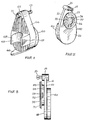
- a cleaning apparatus for a compact disc 17 (Figure7) comprises a pear-shaped support plate 10 having a top surface 11 and a bottom surface 12. At the narrow end the plate 10 has a hollow boss 13 which rotatably accommodates a spindle 14.
- the lower end of the spindle 14 comprises four resilient segments 15 which are dimensioned to permit the spindle 14 to be inserted into the centre aperture 16 of a compact disc case 17a ( Figure7), the segments 15 bearing resiliently outwardly against the inside edge of the centre aperture 16.
- the axis of rotation of the spindle 14 is perpendicular to the plate 10, whereby the latter may be rotated about the centre of the disc 17 in a manner to be described.
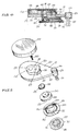
- the top surface 11 of the plate 10 has a housing 18 of which a part 19 remote from the spindle 14 is solid and a part 20 nearest the spindle 14 is hollow, the hollow part 20 having a lateral aperture 21 opening into the top surface 11 of the plate 10 where it faces the spindle 14.
- the hollow part 20 of the housing 18 accommodates a gear wheel 22 whose teeth 23 are exposed at and project slightly beyond the housing 18 at the lateral aperture 21.
- the gear wheel is rotatably retained in the housing 18 by a bolt 26 which passes with slight tolerance through an aperture 27 in the top of the hollow part 20 and onto which the gear wheel 22 is threaded in the manner of a nut.
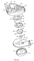
- the gear wheel 22 is non-rotatably secured to a cleaning pad holder mounted on the underside of the support plate 10, the cleaning pad holder being formed in two parts, an upper part 24 and a lower part 25.
- the upper part 24 of the cleaning pad holder 24/25 which passes with slight clearance through a circular aperture 39 in the plate 10, is threaded on the bolt 26 and securely fixed relative to the gear wheel 22, either by adhesive or simply by tightening up against the underside of the gear wheel 22.
- the lower part 25 of the cleaning pad holder 24/25 clips removably into the upper part 24.
- a low friction washer (not show) may be inserted between the gear wheel 22 and the top of the hollow housing part 20 to ensure ease of rotation, and it should not be possible for the part 24 or the gear wheel 22 to unscrew from the bolt 26 during rotation of the gear wheel.
- the upper part 24 of the cleaning pad holder 24/ 25 includes a shallow cylinder 28 open at the bottom and having three equiangularly spaced apertures 29 in its circular side wall.
- the lower part 25 of the cleaning pad holder 24/25 includes a flat annular plate 30 having an upwardly facing cylindrical wall 31 of lesser diameter concentric therewith. Externally of the wall 31 the part 25 has three equiangularly spaced radial ramp-like formations 32, and internally of the wall 31 the part 25 has three equiangularly spaced radial ramp-like formations 32, and internally of the wall 31 the part 25 has a central aperture 33 in the plate 30 and three equiangularly spaced slots 34 extending radially from the aperture 33.
- the wall 31 of the lower part 25 fits snugly within the side wall of the cylinder 28 of the upper part 24, the formations 32 snapping into position in the apertures 29.
- a cleaning pad 35 is removably mounted on the lower surface ot the lower part 25 of the cleaning pad holder 24/25.
- the cleaning pad 35 comprises a disc of fibrous material of substantially the same diameter as the plate 30, a concentric inner portion 36 of the pad being partially severed from the surrounding outer annular portion 37 but being joined thereto by three equiangular strips of material 38 which permit the inner portion 36 be displaced axially relative to the outer portion 37.
- the diameter of the inner portion 36 of the pad 35 is greaterthan that of the central aperture 33 in the plate 30, which permits the cleaning pad 35 to be attached to the lower part 25 of the cleaning pad holder 24/25 by pushing the inner portion 36 through the aperture 33 into the space behind the plate 30 and within the wall 31, the strips of material 38 passing through the slots 34.
- the cleaning pad 35 is self-retaining on the cleaning pad holder 24/25, the outer annular portion 37 abutting against the annular plate 30 and the inner portion 37 abutting against the annular plate 30 and the inner portion 36 being recessed below
- a knob 40 is mounted on the top surface 11 of the support plate 10 for rotation about an axis substantially parallel to but laterally offset from the axis of the spindle 14.
- the knob 40 is in the form of a shallow hollow cylinder open at the bottom and has a central spindle 41.
- the spindle 41 is rotatably accomodated in an aperture 42 which passes through the solid part 19 of the housing 18 and into the support plate 10.
- the internal periphery of the knob 40 is formed with a circular set of teeth 43 coaxial with the axis of rotation of the knob.
- the knob 40 fits over the housing 18 as shown, and the internal teeth 43 thereof mesh with the teeth 23 of the gear wheel 22 where the latter are exposed at the lateral aperture 21 of the housing 18.
- rotation of the knob 40 relative to the support plate 10 will cause rotation of the cleaning pad holder 24/25 relative to the plate 10 and, since there are many more teeth on the inside of the knob 40 than on the gear wheel 22, the arrangement comprises a step-up gear with the pad holder rotating much faster relative to the plate 10 than the knob 40.
- the compact disc 17 when not in use is stored in the compact disc case 17a.
- the case 17a comprises a housing 117 for the disc 17, the housing 117 having a hinged lid 118 attached thereto.
- the housing 117 has its centre aperture 16 provided in a boss 16a having teeth 1.
- the compact disc 17 generally comprises an observe side having indicia thereon, which provide details as to the titles etc. of the tracks on the disc, and a reverse or playing side 17b.
- the observe side is exposed to the viewer when the lid 118 is lifted. Accordingly, to clean the playing side 1, it is necessary to invert the disc 17 so that the playing side 17b is uppermost in the housing 117.
- the boss 16a engages with the hole of disc 17 thereby preventing rotation of the disc 17 in the housing 117.
- a plurality of cleaning pads 35 may be retained simultaneously on the cleaning pad holder 24/25.
- the exposed cleaning pad may be quickly and easily removed when it has become sufficiently contaminated to warrant the use of a new cleaning pad. It may be desirable to interpose between each of the cleaning: pads a fluid impervous membrane so as to enable only the cleaning pad which is currently in use to be exposed to the application of the cleaning fluid.
- the apparatus described above has a protective housing 44 ( Figures 1 and 6) in which the apparatus may be kept while not in use.
- the housing 44 is essentially pear-shaped corresponding to the shape of the support plate 10, is open on one side (not shown) to receive the plate 10 snugly therein and has a base having apertures therein. The apertures provide ventilation holes to enable the cleaning pad 35 to dry off with the apparatus retained in the housing 44.
- the apparatus is retained in the housing 44 by the spindle segments 15 snapping into a boss 45 at the corresponding end of the housing 44.
- the housing 44 has a flat plate 46 at the opposite end to the boss 45, the plate 46 permitting the apparatus in the housing to be stood on one end for storage ( Figure 1).
- the base supports a pair of flanges 47 defining a U-shaped recess 48 in which a bottle of cleaning fluid may be kept.
- the pad holder 24/25 may be driven from the spindle 14 rather than from the knob 40.
- a step-up gear mechanism may be provided between the spindle 14 and the pad holder 24/25 to achieve the same result of high speed rotation of the latter when the support plate 10 is rotated by the knob 40.
- the knob 40 is not connected to the pad holder 24/25, but is freely rotatable relative to the support plate 10.
Landscapes
- Cleaning In General (AREA)
- Cleaning Or Drying Semiconductors (AREA)
- Photosensitive Polymer And Photoresist Processing (AREA)
- Manufacture Or Reproduction Of Printing Formes (AREA)
- Manufacturing Of Magnetic Record Carriers (AREA)
Claims (8)
Priority Applications (1)
| Application Number | Priority Date | Filing Date | Title |
|---|---|---|---|
| AT86302671T ATE48332T1 (de) | 1985-04-12 | 1986-04-10 | Reinigungsgeraet fuer aufzeichnungsplatte. |
Applications Claiming Priority (2)
| Application Number | Priority Date | Filing Date | Title |
|---|---|---|---|
| IE93485 | 1985-04-12 | ||
| IE934/85A IE56926B1 (en) | 1985-04-12 | 1985-04-12 | Apparatus for cleaning a record disc |
Publications (2)
| Publication Number | Publication Date |
|---|---|
| EP0198671A1 EP0198671A1 (de) | 1986-10-22 |
| EP0198671B1 true EP0198671B1 (de) | 1989-11-29 |
Family
ID=11019958
Family Applications (1)
| Application Number | Title | Priority Date | Filing Date |
|---|---|---|---|
| EP86302671A Expired EP0198671B1 (de) | 1985-04-12 | 1986-04-10 | Reinigungsgerät für Aufzeichnungsplatte |
Country Status (7)
| Country | Link |
|---|---|
| US (1) | US4759093A (de) |
| EP (1) | EP0198671B1 (de) |
| AT (1) | ATE48332T1 (de) |
| AU (1) | AU586675B2 (de) |
| CA (1) | CA1261280A (de) |
| DE (1) | DE3667218D1 (de) |
| IE (1) | IE56926B1 (de) |
Families Citing this family (7)
| Publication number | Priority date | Publication date | Assignee | Title |
|---|---|---|---|---|
| US4654917A (en) * | 1985-06-17 | 1987-04-07 | Recoton Corporation | Compact disc cleaner |
| JPS62260472A (ja) * | 1986-05-06 | 1987-11-12 | Tokyo Electric Co Ltd | 通信端末装置 |
| GB9017103D0 (en) * | 1990-08-03 | 1990-09-19 | Nicolaidis Raphael | A pipe and a process for its production |
| CN2284438Y (zh) * | 1996-12-02 | 1998-06-17 | 柏盈实业股份有限公司 | 镭射碟片清洁器 |
| US6000085A (en) * | 1998-07-07 | 1999-12-14 | Taiwan Bor Ying Corporation | Compact disc cleaner |
| USD535072S1 (en) * | 2003-10-31 | 2007-01-09 | Marc Louis Robert Jaricot | Compact disc cleaner |
| USD493264S1 (en) | 2003-12-05 | 2004-07-20 | Calibre International, Llc | CD cleaner |
Citations (2)
| Publication number | Priority date | Publication date | Assignee | Title |
|---|---|---|---|---|
| US3150401A (en) * | 1963-01-31 | 1964-09-29 | William W Taylor | Phonograph record cleaner |
| GB2171241A (en) * | 1985-02-14 | 1986-08-20 | Joseph Frederick Fritsch | A cleaning device |
Family Cites Families (9)
| Publication number | Priority date | Publication date | Assignee | Title |
|---|---|---|---|---|
| US4166626A (en) * | 1977-12-23 | 1979-09-04 | California Sounds, Ltd. | Record cleaner |
| DE2922397A1 (de) * | 1979-06-01 | 1980-12-04 | Braun Ag | Reinigungsgeraet fuer schallplatten |
| DE2923150A1 (de) * | 1979-06-07 | 1980-12-18 | Peter Nawrath | Geraet zur trockenreinigung von schallplatten |
| GB2066998B (en) * | 1979-11-27 | 1983-06-02 | Hitachi Maxell | Self-propelled record cleaner |
| US4486916A (en) * | 1981-10-15 | 1984-12-11 | Allsop, Inc. | Phonorecord cleaner |
| BE896398R (fr) * | 1983-04-07 | 1983-08-01 | Staar Sa | Dispositif de nettoyage pour disques, |
| BE895177A (fr) * | 1982-11-29 | 1983-03-16 | Staar Sa | Dispositif de nettoyage pour disques |
| US4561142A (en) * | 1984-01-06 | 1985-12-31 | International Jensen Incorporated | Disc cleaner |
| US4556433A (en) * | 1984-04-16 | 1985-12-03 | Allsop, Inc. | Apparatus and method for cleaning digital audio discs |
-
1985
- 1985-04-12 IE IE934/85A patent/IE56926B1/en not_active IP Right Cessation
-
1986
- 1986-03-14 US US06/839,690 patent/US4759093A/en not_active Expired - Fee Related
- 1986-04-10 DE DE8686302671T patent/DE3667218D1/de not_active Expired - Lifetime
- 1986-04-10 EP EP86302671A patent/EP0198671B1/de not_active Expired
- 1986-04-10 AT AT86302671T patent/ATE48332T1/de not_active IP Right Cessation
- 1986-04-11 CA CA000506420A patent/CA1261280A/en not_active Expired
- 1986-04-11 AU AU55997/86A patent/AU586675B2/en not_active Ceased
Patent Citations (2)
| Publication number | Priority date | Publication date | Assignee | Title |
|---|---|---|---|---|
| US3150401A (en) * | 1963-01-31 | 1964-09-29 | William W Taylor | Phonograph record cleaner |
| GB2171241A (en) * | 1985-02-14 | 1986-08-20 | Joseph Frederick Fritsch | A cleaning device |
Non-Patent Citations (1)
| Title |
|---|
| Certified copy of the Irish Patent application no. 934185 dated 12/4/85 * |
Also Published As
| Publication number | Publication date |
|---|---|
| AU586675B2 (en) | 1989-07-20 |
| IE56926B1 (en) | 1992-01-29 |
| ATE48332T1 (de) | 1989-12-15 |
| IE850934L (en) | 1986-10-12 |
| DE3667218D1 (de) | 1990-01-04 |
| US4759093A (en) | 1988-07-26 |
| EP0198671A1 (de) | 1986-10-22 |
| CA1261280A (en) | 1989-09-26 |
| AU5599786A (en) | 1986-10-16 |
Similar Documents
| Publication | Publication Date | Title |
|---|---|---|
| EP0206589B1 (de) | Reinigungsgerät für Aufzeichnungsplatte | |
| US4783870A (en) | Compact disk cleaner | |
| US4520470A (en) | Cleaning device for discs | |
| US5584089A (en) | CD case with a platter and cleaning means driven by a single driving device | |
| KR970063243A (ko) | 디스크 클리너 장치 | |
| US4662025A (en) | Cleaning device | |
| GB2157877A (en) | Apparatus for cleaning audio discs | |
| EP0198671B1 (de) | Reinigungsgerät für Aufzeichnungsplatte | |
| US4709437A (en) | Compact disc cleaner | |
| US4947505A (en) | Apparatus for cleaning a record disc | |
| KR910008695A (ko) | 디스크 기억장치용 유지 클램프 | |
| EP0640969B1 (de) | Reinigungsgerät | |
| US5813081A (en) | Circular device for cleaning the ends of optical fibers | |
| US6766550B1 (en) | Compact disk labeling, cleaning and repairing systems | |
| JPH0689538A (ja) | 光学または磁気光学ディスク用クリーニング装置 | |
| JPH0356934Y2 (de) | ||
| JP2707895B2 (ja) | ディスククリーナ | |
| JPH0356935Y2 (de) | ||
| EP0246298A1 (de) | Antriebsmechanismus für speicherplatte und nabe. | |
| IE73199B1 (en) | A disc record cleaning device | |
| JPS6252779A (ja) | 情報記録円盤の手動クリ−ニング装置 | |
| IES59751B2 (en) | A disc record cleaning device | |
| GB2269740A (en) | Compact disc cleaner. | |
| GB2234847A (en) | A disc record cleaner | |
| KR960704316A (ko) | 1.8인치 폼 팩터를 갖춘 제거식 카트리지 디스크 드라이브(removable cartridge disk drive with a 1.8 inch form factor) |
Legal Events
| Date | Code | Title | Description |
|---|---|---|---|
| PUAI | Public reference made under article 153(3) epc to a published international application that has entered the european phase |
Free format text: ORIGINAL CODE: 0009012 |
|
| AK | Designated contracting states |
Kind code of ref document: A1 Designated state(s): AT BE CH DE FR GB IT LI LU NL SE |
|
| 17P | Request for examination filed |
Effective date: 19870320 |
|
| 17Q | First examination report despatched |
Effective date: 19881206 |
|
| GRAA | (expected) grant |
Free format text: ORIGINAL CODE: 0009210 |
|
| AK | Designated contracting states |
Kind code of ref document: B1 Designated state(s): AT BE CH DE FR GB IT LI LU NL SE |
|
| PG25 | Lapsed in a contracting state [announced via postgrant information from national office to epo] |
Ref country code: AT Effective date: 19891129 Ref country code: BE Effective date: 19891129 Ref country code: IT Free format text: LAPSE BECAUSE OF FAILURE TO SUBMIT A TRANSLATION OF THE DESCRIPTION OR TO PAY THE FEE WITHIN THE PRE;WARNING: LAPSES OF ITALIAN PATENTS WITH EFFECTIVE DATE BEFORE 2007 MAY HAVE OCCURRED AT ANY TIME BEFORE 2007. THE CORRECT EFFECTIVE DATE MAY BE DIFFERENT FROM THE ONE RECORDED.SCRIBED TIME-LIMIT Effective date: 19891129 |
|
| REF | Corresponds to: |
Ref document number: 48332 Country of ref document: AT Date of ref document: 19891215 Kind code of ref document: T |
|
| REF | Corresponds to: |
Ref document number: 3667218 Country of ref document: DE Date of ref document: 19900104 |
|
| ET | Fr: translation filed | ||
| PG25 | Lapsed in a contracting state [announced via postgrant information from national office to epo] |
Ref country code: LU Free format text: LAPSE BECAUSE OF NON-PAYMENT OF DUE FEES Effective date: 19900430 |
|
| PLBI | Opposition filed |
Free format text: ORIGINAL CODE: 0009260 |
|
| 26 | Opposition filed |
Opponent name: WORK ENVIRONMENT SYSTEM TECHNOLOGY Effective date: 19900827 |
|
| NLR1 | Nl: opposition has been filed with the epo |
Opponent name: WORK ENVIRONMENT SYSTEM TECHNOLOGY |
|
| PGFP | Annual fee paid to national office [announced via postgrant information from national office to epo] |
Ref country code: SE Payment date: 19920323 Year of fee payment: 7 |
|
| PGFP | Annual fee paid to national office [announced via postgrant information from national office to epo] |
Ref country code: FR Payment date: 19920327 Year of fee payment: 7 |
|
| PGFP | Annual fee paid to national office [announced via postgrant information from national office to epo] |
Ref country code: CH Payment date: 19920423 Year of fee payment: 7 |
|
| PGFP | Annual fee paid to national office [announced via postgrant information from national office to epo] |
Ref country code: NL Payment date: 19920430 Year of fee payment: 7 |
|
| PLAB | Opposition data, opponent's data or that of the opponent's representative modified |
Free format text: ORIGINAL CODE: 0009299OPPO |
|
| PGFP | Annual fee paid to national office [announced via postgrant information from national office to epo] |
Ref country code: DE Payment date: 19920630 Year of fee payment: 7 |
|
| R26 | Opposition filed (corrected) |
Opponent name: WORK ENVIRONMENT SYSTEM TECHNOLOGY Effective date: 19900827 |
|
| PGFP | Annual fee paid to national office [announced via postgrant information from national office to epo] |
Ref country code: GB Payment date: 19930326 Year of fee payment: 8 |
|
| PG25 | Lapsed in a contracting state [announced via postgrant information from national office to epo] |
Ref country code: SE Effective date: 19930411 |
|
| PG25 | Lapsed in a contracting state [announced via postgrant information from national office to epo] |
Ref country code: CH Free format text: LAPSE BECAUSE OF NON-PAYMENT OF DUE FEES Effective date: 19930430 Ref country code: LI Free format text: LAPSE BECAUSE OF NON-PAYMENT OF DUE FEES Effective date: 19930430 |
|
| PG25 | Lapsed in a contracting state [announced via postgrant information from national office to epo] |
Ref country code: NL Effective date: 19931101 |
|
| NLV4 | Nl: lapsed or anulled due to non-payment of the annual fee | ||
| PG25 | Lapsed in a contracting state [announced via postgrant information from national office to epo] |
Ref country code: FR Effective date: 19931229 |
|
| REG | Reference to a national code |
Ref country code: CH Ref legal event code: PL |
|
| PG25 | Lapsed in a contracting state [announced via postgrant information from national office to epo] |
Ref country code: DE Effective date: 19940101 |
|
| REG | Reference to a national code |
Ref country code: FR Ref legal event code: ST |
|
| PG25 | Lapsed in a contracting state [announced via postgrant information from national office to epo] |
Ref country code: GB Effective date: 19940410 |
|
| RDAG | Patent revoked |
Free format text: ORIGINAL CODE: 0009271 |
|
| STAA | Information on the status of an ep patent application or granted ep patent |
Free format text: STATUS: PATENT REVOKED |
|
| GBPC | Gb: european patent ceased through non-payment of renewal fee |
Effective date: 19940410 |
|
| 27W | Patent revoked |
Effective date: 19940815 |
|
| EUG | Se: european patent has lapsed |
Ref document number: 86302671.2 Effective date: 19931110 |