EP0198676A2 - Zweikurvenförmige Linsen - Google Patents
Zweikurvenförmige Linsen Download PDFInfo
- Publication number
- EP0198676A2 EP0198676A2 EP86302679A EP86302679A EP0198676A2 EP 0198676 A2 EP0198676 A2 EP 0198676A2 EP 86302679 A EP86302679 A EP 86302679A EP 86302679 A EP86302679 A EP 86302679A EP 0198676 A2 EP0198676 A2 EP 0198676A2
- Authority
- EP
- European Patent Office
- Prior art keywords
- bicurve
- lenses
- lens
- center
- convergent
- Prior art date
- Legal status (The legal status is an assumption and is not a legal conclusion. Google has not performed a legal analysis and makes no representation as to the accuracy of the status listed.)
- Withdrawn
Links
Images


Classifications
-
- G—PHYSICS
- G02—OPTICS
- G02B—OPTICAL ELEMENTS, SYSTEMS OR APPARATUS
- G02B5/00—Optical elements other than lenses
-
- G—PHYSICS
- G02—OPTICS
- G02B—OPTICAL ELEMENTS, SYSTEMS OR APPARATUS
- G02B3/00—Simple or compound lenses
- G02B3/02—Simple or compound lenses with non-spherical faces
Definitions
- the present invention relates to optical lenses which have a double curve in one of their two surfaces, or in both, called bicurve lenses, bicurve-conical lenses like wise being described, alternatives of ther former and in which one of its surfaces is conical, and bicurve-monocurve lenses, in which one of the surfaces has only one spherical curve.
- these can be of two kinds, namely: a) that wherein the lens is wider at the edges than at the center, in which it has the minimum width, but the curve which descends toward the center is not concave but convex, so that, on a cross-section through the lens center, the curved surface presents the ap pearance of being formed by two ridges which ascend toward the edges in two increasing convex lines; and b) that where in the lens is narrower at the edges than at the center, where it has the maximum width, but the curve which ascends from the edge toward the center is not convex but concave, so that on a cross-section through the lens center, the curved surface has the appearance of being formed by two depressions which descend from the center toward the edges in two diminishing concave lines.
- the lens sections described have respectively the appearance which would be produced, on the one hand, dividing into two parts through the center a conventional or traditional convex lense then assembling both parts and changing their place and, on the other hand, the appearance which a conventional or traditional concave lense would have as a result if, divided into two parts at the center, these had had their place changed.
- Bicurve-conical lenses which likewise constitute an object of the present invention, have one conical surface and the other bicurve, the conical surface having a convex or concave appearance.
- the bicurve surface constitutes the opposite side to the conical side and can have a twofold aspect, namely: a) that of two convex protuberances (of lenticular curvature), which are situated on each side of the focal axis and are joined by the center, thereby forming a depression toward the centre or central bicurve--concavo vertex or apex and b) that of two lenticular concavities, likewise situated on-each side of the focal axis and similarly joined by the center or focal axis in the part opposite to the cone vertex or apex, whereby they form a convexity at the center.
- the bicurve-monocurve lenses like the earlier ones, still having a bicurve surface structure and the other surface is formed by a single spherical surved surface, of convex configuration or concave configuration.
- An f/16 objective for example, always means that the opening of the objective is 16 times smaller than the focal distance.
- the ligh ⁇ t which would be obtained with an f/4 would be that collected by a surface occupied by a circle whose diameter would be the fourth part of the focal distance; that is:
- the second objective at the same f/4 aperture, turns out 7 times more luminous according to the example given.
- the light admission surface will be:
- the luminosity of a bicurve lens objective is 31 times greater than that of a traditional objective.
- the outer cap is thicker (hence it is the one producing the least aberration, insofar as it is the one closest to the focal plane and deflects the light less) and the center is thinner (which would be what would produce the light aberration, on being further away and deflecting the light more intensely).
- a normal lens having a diameter of 16 mm., whose edges may have been suppressed will have a suppressed surface of 188.40 mm 2
- a bicurve of the same size whose center will have been suppressed in a radius of 2 mm, will have a suppressed surface of 12.56 mm 2
- the bicurve lenses are characterized in that they present a double curvature in one of their surfaces or in both, or in that one surface can be just conical or just monocurve, the lens being able to be wider at the edges than at the center, the curve which descends toward the center being convex, so-that, on a cross-section through the center of the lens, at least one of its surfaces is curved and has the appearance of being formed by two ridges which ascend toward the edges in two increasing convex lines, or the lens'is narrower at the edges than at the center, where it acquires the maximum width, the curve which ascends from the edge toward the cen ter being concave, so that, on a cross-section of the center of the lens, at least one of its surfaces is curved and had the appearance of being formed by two depressions which descend from the center until the edges in two decreasing concave lines.
- the bicurve lenses according to the invention are characterized in that they can have one surface conical and the other one bicurve, and likewise in that they can have one surface monocurve and the other one bicurve.
- bicurve lenses can be exclusively bicurve and with double curvature in a single surface, the other one being flat or both surfaces bicurve which can be placed in the same or in the opposite direction, the flat bicurve-convexo, flat bicurve-concavo, bicurve-biconvexo, bicurve-biconcavo, bicurve-convexo-concavo and bicurve-concavo-convexo ones, all being exclusively bicurve lenses.
- flat bicurve-convexo, bicurve-biconvexo and bicurve-convexo-concavo lenses being convergent-divergent
- bicurve-concavo lenses being flat
- bicurve-biconcavo and bicurve-concavo-convex lenses being divergent-convergent.
- the convergent-divergent lenses gather the light, making the rays cross, in a circumference (whoce radius coincides with that of the lens), called "focal circumference" and which is to be found behind the lens, separated from the edges of this'by the same focal distance as the one which, the circumstances being the same, would correspond to a normal convergent lens, and the focal axis, instead of in the center, is situated at the ends, occupying a cylindrical surface.
- the divergent-convergent lenses separate from one another the refracted light rays, but making them fall toward the interrior, toward the central axis, in which they cross,and their inverse prolongation makes them likewise cross forming a virtual circumference ("focal circumference"), which have the same diameter as the lens, being situated in front of it and separated from the edges of this by the same focal distance as that which, under the same conditions, would correspond to a normal divergent lens, and the focal axis, instead of in the center, is situated at the ends, occupying a cyclindrical surface.
- focal circumference virtual circumference
- the bicurve lenses object of the invention can join one another forming optical systems, in such a way that, when the first lens is convergent-divergent, the second one can be of the same nature or divergente-convergente; in the former case the light rays are projected in parallel beams forming a circular cap whose width will depend on the distance between both lenses, while in the case of a convergent-divergent lens with one divergent-convergent one, the rays are projected in parallel beams forming a circular cap, whose width will likewise depend on the distance between both lenses.
- the bicurve lenses in accord with the invention are characterized in that when the optical system formed by them has to incorporate a diaphragm, this is placed in the center of the objective, occupying the least possible space, such that, from the center, it closes the objective extending toward the outside, the opaque part of the light commencing in the center of the lens and extending out, in circular fashion, toward the outside until occupying the entire opening, the transparent part of the outer circular cap being non-diaphragammed and this circular cap being narrower the more extended the diaphragm.
- a diaphragm this is placed in the center of the objective, occupying the least possible space, such that, from the center, it closes the objective extending toward the outside, the opaque part of the light commencing in the center of the lens and extending out, in circular fashion, toward the outside until occupying the entire opening, the transparent part of the outer circular cap being non-diaphragammed and this circular cap being narrower the more extended the diaphragm.
- the bicurve lenses object of the invention increase the luminosity, the field depth and diminish the spherical aberration.
- Flat bicurve-concavo, bicurve-biconcavo and bi- curveconcavo-convexo lenses are divergent-convergent, conventionally symbolized with a vertical stroke which,divided through the middle by an axis, is completed at its ends by two arcs curved in the direction opposite to the axis.
- bicurve-convexo conic-convexo (figure lc)
- bicurve-convexo-conic-concavo (figure ld)
- bicurve-biconcavo-conic-convexo (figure le)
- bicurve-concavo-conic--concavo (figure 1f).
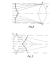
- Figure 2 shows the behaviour of the light on being refracted by convergent-divergent lenses, such as flat bicurve-convexo, bicurve-convexo and bicurve-convexo and bicurve-convexo-concavo lenses shown in figures la, 1 9 and li.
- a convergent-divergent lens gathers the refracted light in a circumference, whose radius coincides with that of the lens, called "focal circumference" (CF), which is to be found separated from its edges by the same focal distance which, in the same circumstances, corresponds to a normal convergent lens, in which the diameter of the focal circumference is comprised between F l and F 2 .
- CF focal circumference
- the focal axis is situated at the ends, in a cylindrical surface, instead of in the center as occurring in the case of a traditional convergent lens. It is observed that, in effect, the focal distance is the same as in the case of a traditional convergent lens, and that the rays converge toward the outside forming not a focus but a circumference in which the rays cross (focal circumference), whose diameter coincides with that of the lens.
- a divergent-convergent lens is represented such as is the case of flat bicurve-concaveo, bicurve-concavo and bicurve-concavo-convexo lenses represented in figures lb, 1h and lj.
- the divergente-convergent lens separates from one another the refracted light rays, but making them fall toward the central lens axis, in which they cross, and their inverse prolongation makes them likewise cross forming a virtual circumference (focal circumference), situated in front of the lens and separated from its edges by the same focal distance which, in equal conditions, would corre spond to a normal divergent lens, in which the diameter of the focal circumference is comprised between F 1 and F 2 .
- the focal axis is situated at the ends, occupying a cyclindrical surface (CS) instead of in the center. It is observed that, in effect, the focal distance is the same as in the case of a traditional divergent lens, and that the rays diverge among themselves but with direction to the lens axis forming not a virtual focus but a virtual focal circumference, in which the prolongations of the rays cross and whose diameter coin cides with that of the lens.
- CS cyclindrical surface
- the behaviour of the light is observ ed on passing through a convergente-divergente lens followed by another of the same nature, situated after the rays have crossed in the focal circumference (inverse afocal system).
- the second lens is necessarily of greater diameter than the first one.
- the light path just as this can be observed, has now likewise concentrated itself in a circular cap, with a greater radius than in the preceding case.
- the rays remain parallel but in inverted position with respect to the original one.
- the parallely placed light after the second refraction can be concentrated on a point focus by means of a traditional convergent lens.
- the light in these objectives tends to diverge toward the exterior, toward the external circles of the lenses.
- the diaphragm (when it is of interest to use diaphragammed objectives, for which it is going to be assumed that these are those relating to photo- graphical optics) should be situated in the middle of the lens, occupying the least possible space, and from the center closing the objective stretching out toward the outside. Therefore the diaphragm will have to operate just the contrary to that in the ordinary present-day system:
- the opaque part of the light commences in the center of the lens and, in circular fashion, extends toward the exterior until occupying the whole lens surface; the transparent part will be the outer circular lens cap. This circular cap will be more narrow the more extended the diaphragm.
- the chamber will receive that much less light the greater the extension (the aperture to the inverse) of the diaphragm.
- the central energetic concentration of the emerg ing light beam increases and the surface one diminishes in a ratio which ranges from the infinite to zero.
- the central ray theoretically has infinite energy and the overall energy of the rays of the outer circle of the beam is equal to zero.
- the progression-- is such that the principle is complied with that the circumference situated in the center of the radius of the emerging beam is equal to the unit, understanding as unit the intensity of original incident energy before its transformation.
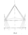
- FIGs 9, 10 and 11 visually explain the foregoing.
- a beam (already concentrated by conical mirrors or by conical lenses) falls parallely on the bicurve-biconvexo surface (A', ' B'-B'-C') and disassociates in a circular beam whose ends would have to cross according to the two focuses f' which represent the diameter of the circle.
- A-B-C the bicurve-biconvexo surface
- A-B-C the convergent conical surface
- the rays which arrive at this focus do so with an inclination as thought they proceeded from points situated in the infinite after having been collected by a traditional convergent curve lens. This has been represented in more schematic form in figures 10 and 11.
- FIG. 9 to 11 corresponds to a conical-convexo-bicurve-bioconvexolens.
- the other three lenses shown in figures ld, le and lf and their application will vary depending on the angle at which the light beam falls which it is sought to distribute, and depending on the way in which, among them, it is sought to combine them, since the conical mirrors and the conical lens can secure this, that the emerging energy be parallely convergent or divergent.
- the bicurve lens to have a monocurve side (concave or convex). Thereby four combinations are possible.
- the advantage lies in their allowing greater versatility of application and combination with exclusively bicurve lens and with exclusively curved lens.
Landscapes
- Physics & Mathematics (AREA)
- General Physics & Mathematics (AREA)
- Optics & Photonics (AREA)
- Lenses (AREA)
- Lens Barrels (AREA)
Applications Claiming Priority (4)
| Application Number | Priority Date | Filing Date | Title |
|---|---|---|---|
| ES542197A ES8604355A1 (es) | 1985-04-12 | 1985-04-12 | Lentes bicurvoconicas |
| ES542197 | 1985-04-12 | ||
| ES542267A ES8604356A1 (es) | 1985-04-16 | 1985-04-16 | Lentes bicurvas |
| ES542267 | 1985-04-16 |
Publications (2)
| Publication Number | Publication Date |
|---|---|
| EP0198676A2 true EP0198676A2 (de) | 1986-10-22 |
| EP0198676A3 EP0198676A3 (de) | 1988-10-12 |
Family
ID=26156097
Family Applications (1)
| Application Number | Title | Priority Date | Filing Date |
|---|---|---|---|
| EP86302679A Withdrawn EP0198676A3 (de) | 1985-04-12 | 1986-04-10 | Zweikurvenförmige Linsen |
Country Status (1)
| Country | Link |
|---|---|
| EP (1) | EP0198676A3 (de) |
Cited By (4)
| Publication number | Priority date | Publication date | Assignee | Title |
|---|---|---|---|---|
| EP0458788A4 (en) * | 1989-02-17 | 1992-05-06 | University Of Houston-University Park | Optical lenses and related devices |
| WO2006064632A1 (en) * | 2004-12-14 | 2006-06-22 | Casio Computer Co., Ltd. | Light source unit and projector system |
| WO2006095587A1 (en) * | 2005-03-07 | 2006-09-14 | Casio Computer Co., Ltd. | Light source unit and projector apparatus |
| WO2007058070A3 (en) * | 2005-11-18 | 2007-10-25 | Casio Computer Co Ltd | Light source unit and projector system |
Family Cites Families (1)
| Publication number | Priority date | Publication date | Assignee | Title |
|---|---|---|---|---|
| US2759393A (en) * | 1952-10-25 | 1956-08-21 | Eastman Kodak Co | Optical aligners employing axicons |
-
1986
- 1986-04-10 EP EP86302679A patent/EP0198676A3/de not_active Withdrawn
Cited By (8)
| Publication number | Priority date | Publication date | Assignee | Title |
|---|---|---|---|---|
| EP0458788A4 (en) * | 1989-02-17 | 1992-05-06 | University Of Houston-University Park | Optical lenses and related devices |
| WO2006064632A1 (en) * | 2004-12-14 | 2006-06-22 | Casio Computer Co., Ltd. | Light source unit and projector system |
| US7607787B2 (en) | 2004-12-14 | 2009-10-27 | Casio Computer Co., Ltd. | Light source unit and projector system |
| WO2006095587A1 (en) * | 2005-03-07 | 2006-09-14 | Casio Computer Co., Ltd. | Light source unit and projector apparatus |
| KR100857936B1 (ko) | 2005-03-07 | 2008-09-09 | 가시오게산키 가부시키가이샤 | 광원 유닛 및 프로젝터 장치 |
| US7819533B2 (en) | 2005-03-07 | 2010-10-26 | Casio Computer Co., Ltd. | Light source unit and projector apparatus |
| CN101091384B (zh) * | 2005-03-07 | 2010-12-08 | 卡西欧计算机株式会社 | 光源单元与投影仪装置 |
| WO2007058070A3 (en) * | 2005-11-18 | 2007-10-25 | Casio Computer Co Ltd | Light source unit and projector system |
Also Published As
| Publication number | Publication date |
|---|---|
| EP0198676A3 (de) | 1988-10-12 |
Similar Documents
| Publication | Publication Date | Title |
|---|---|---|
| CN217821122U (zh) | 基于超透镜的椭圆光束整形系统及具有其的激光系统 | |
| US4205902A (en) | Laser beam expander | |
| CA2124466A1 (en) | Projector | |
| EP0819973B1 (de) | Fresnellinsen-Folie für einen Durchlicht-Projektionsschirm | |
| JPS6380219A (ja) | フレア拒否特性を持つた広角レンズ方式 | |
| US20050041307A1 (en) | Directed Fresnel lenses | |
| CN114578555B (zh) | 一种光场显示装置、vr设备、显示装置以及显示方法 | |
| GB1125880A (en) | A panoramic objective for photography or projection | |
| US4695136A (en) | Projection objective assembly | |
| US2303113A (en) | Reflector | |
| EP0198676A2 (de) | Zweikurvenförmige Linsen | |
| US5036438A (en) | Projector-type head lamp for motor vehicles | |
| JPS6058441B2 (ja) | 円柱状の構成成分を有する傾斜させたレンズ要素で構成された反射排除球状光学列 | |
| CN110941097A (zh) | 激光周视探测的圆锥形视场发射光学系统 | |
| US20040032664A1 (en) | Color-corrected collimating lens | |
| JP2003232993A (ja) | 屈折光学系 | |
| GB2322455A (en) | Cylinder lens and plates for beam shaping for an optical pickup | |
| JPS61275701A (ja) | 二曲面レンズ | |
| US2821108A (en) | Deep-field optical objectives | |
| US7342728B2 (en) | Fresnel lens, backprojection screen, and corresponding backprojection system and unit | |
| JP7117611B2 (ja) | ビーム変換光学系および光源装置 | |
| US4367016A (en) | Flat field lens with image splitting effect | |
| US2627204A (en) | Four-component gauss-type photographic objective of high lighttransmitting capacity | |
| JPH0125046B2 (de) | ||
| JP2005292571A (ja) | 回折光学素子及びそれを有する光学系 |
Legal Events
| Date | Code | Title | Description |
|---|---|---|---|
| PUAI | Public reference made under article 153(3) epc to a published international application that has entered the european phase |
Free format text: ORIGINAL CODE: 0009012 |
|
| AK | Designated contracting states |
Kind code of ref document: A2 Designated state(s): AT BE CH DE FR GB IT LI LU NL SE |
|
| PUAL | Search report despatched |
Free format text: ORIGINAL CODE: 0009013 |
|
| AK | Designated contracting states |
Kind code of ref document: A3 Designated state(s): AT BE CH DE FR GB IT LI LU NL SE |
|
| STAA | Information on the status of an ep patent application or granted ep patent |
Free format text: STATUS: THE APPLICATION IS DEEMED TO BE WITHDRAWN |
|
| 18D | Application deemed to be withdrawn |
Effective date: 19890413 |