EP0198706A2 - Verstellbare Leuchte - Google Patents
Verstellbare Leuchte Download PDFInfo
- Publication number
- EP0198706A2 EP0198706A2 EP86302773A EP86302773A EP0198706A2 EP 0198706 A2 EP0198706 A2 EP 0198706A2 EP 86302773 A EP86302773 A EP 86302773A EP 86302773 A EP86302773 A EP 86302773A EP 0198706 A2 EP0198706 A2 EP 0198706A2
- Authority
- EP
- European Patent Office
- Prior art keywords
- arm
- light fitting
- members
- pivots
- magnetic means
- Prior art date
- Legal status (The legal status is an assumption and is not a legal conclusion. Google has not performed a legal analysis and makes no representation as to the accuracy of the status listed.)
- Ceased
Links
Images

Classifications
-
- F—MECHANICAL ENGINEERING; LIGHTING; HEATING; WEAPONS; BLASTING
- F21—LIGHTING
- F21V—FUNCTIONAL FEATURES OR DETAILS OF LIGHTING DEVICES OR SYSTEMS THEREOF; STRUCTURAL COMBINATIONS OF LIGHTING DEVICES WITH OTHER ARTICLES, NOT OTHERWISE PROVIDED FOR
- F21V21/00—Supporting, suspending, or attaching arrangements for lighting devices; Hand grips
- F21V21/14—Adjustable mountings
- F21V21/26—Pivoted arms
-
- F—MECHANICAL ENGINEERING; LIGHTING; HEATING; WEAPONS; BLASTING
- F21—LIGHTING
- F21S—NON-PORTABLE LIGHTING DEVICES; SYSTEMS THEREOF; VEHICLE LIGHTING DEVICES SPECIALLY ADAPTED FOR VEHICLE EXTERIORS
- F21S6/00—Lighting devices intended to be free-standing
- F21S6/002—Table lamps, e.g. for ambient lighting
- F21S6/003—Table lamps, e.g. for ambient lighting for task lighting, e.g. for reading or desk work, e.g. angle poise lamps
-
- F—MECHANICAL ENGINEERING; LIGHTING; HEATING; WEAPONS; BLASTING
- F21—LIGHTING
- F21S—NON-PORTABLE LIGHTING DEVICES; SYSTEMS THEREOF; VEHICLE LIGHTING DEVICES SPECIALLY ADAPTED FOR VEHICLE EXTERIORS
- F21S8/00—Lighting devices intended for fixed installation
Definitions
- This invention relates to adjustable light fittings. More particularly, the invention is concerned with a form of light fitting comprising a support assembly carrying a lamp holder and including an adjustable arm enabling the spatial position of the lamp holder to be varied relative to a structure on which the light fitting is supported.
- a traditional form of anglepoise lamp for example, has a base adapted to rest on a table top or to be clamped to a suitable structure, a first arm pivoted by one end to the base and by the other end to one end of a second arm, and a lamp holder pivoted to the other end of the second arm.
- the axes of the pivots are parallel, ensuring a wide range of adjustment of the lamp holder position with respect to the base.
- lamps of this form have only a limited range of positional adjustment.
- an adjustable light fitting as initially described, and characterised in that the support arm comprises two substantially parallel elongate members arranged to move relative to each other in the lengthwise direction of the arm during adjustment of the support arm, one member comprising permanently magnetic means disposed over a substantial lengthwise portion thereof, and the other member comprising an elongate part magnetically attracted by the magnetic means to urge the two members into frictional contact for retaining the support arm in its adjusted position.
- the friction surfaces are urged together by the magnetic forces so that wear at these surfaces is not a problem and the arm will remain held securely in its adjusted position even after the fitting has been in use for a long time.
- the magnetic means spread along one of the members a strong magnetic force is possible so that additional devices, such as counterweights or springs, to hold the arm in the adjusted position are unnecessary.
- the magnetic means comprises a continuous elongate permanent magnet, although a series of individual magnets distributed along the member could be used.
- the part attracted by the magnetic means is urged into direct contact with the magnetic means, so that the frictional forces opposing relative movement of the two members are determined mainly by the magnetic forces. This facilitates control of the frictional forces during manufacture, and their stability over long term use of the fitting.
- the support arm may be extensible, the two members moving relative to each other in a telescopic arrangement.
- the support arm may be pivotally adjustable, the two members of the support arm being connected to a further part of the support assembly by respective pivots having parallel axes. A distance separating the pivot axes ensures that the two members move with respect to each other in the longitudinal direction when the arm is pivoted to change the lamp holder position.
- the pivots are adapted to preclude movement of the members towards and away from each other in a lateral direction, thus maintaining the members in frictional contact.
- the support arm of the invention can be employed with advantage in an anglepoise lamp and in a preferred embodiment of a lamp of this type two such arms are provided.
- the arms are connected end-to-end by a coupling member, and one arm is pivoted to a base while the other arm carries the lamp holder.
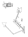
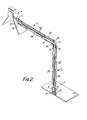
- the lamp depicted in Figures 1 to 3 of the drawings comprises: a base 1 which is adapted to rest on a support surface although it could be fashioned in the form of a clamp in a manner known per se; a lower arm 2 pivoted by one end to the base 1; a coupling member 3 connected pivotally to the other end of the lower arm 2; an upper arm 4 having one end connected pivotally to the member 3 and the other end connected pivotally to a second coupling member 5; and, a lamp holder 6 including a bulb holder, shade and push button switch, pivoted on the member 5.
- the axes of the pivots are parallel to each other and perpendicular to the plane of the arms 2, 4 enabling position of the lamp holder 6 to be adjustable within a wide range of positions in said plane.
- the lamp holder may include a rotational coupling to allow angular adjustment about an axis perpendicular to the axis of its pivotal connection to member 5.
- the lower arm 2 is defined by two elongate members 10, 11 of channel shaped cross-section, the internal width of the first channel member 10 matching the external width of the second channel member 11 and the two members being nested together with their side walls lapping as seen in Figure 3.
- the channel members 10, 11 are pivoted by respective pins 12, 13 between a pair of upstanding brackets 14 provided on the base.
- the axes of the pins 12, 13 are parallel and in the same horizontal plane.
- the upper ends of the channel members are similarly pivoted to the coupling member 3 by respective pins 15, 16 whose axes are also parallel and located in the same horizontal plane.
- the distance separating pins 15, 16 is equal to that between pins 12, 13, so that the two channel members, the brackets 14 and the coupling member 3 constitute a parallelogram and as a consequence the channel members 10, 11 always remain parallel throughout the pivotal adjustment of the arm 2 relative to base 1. During such movement of the arm the channel members are displaced longitudinally with respect to each other and also undergo some slight relative lateral movement.
- channel member 11 Firmly attached to the inside of channel member 11 is an elongate permanent magnet 20 which extends over a major part of the length of the arm 2.
- the other channel member 10 carries a metal bar 22 which is attracted into frictional engagement with the magnet 20 under the influence of the magnetic force.
- the ends of the bar 22 are bent through 90 0 and extend through holes provided in the channel member 10, whereby the bar is free to move laterally towards and away from the magnet, but is held fast for longitudinal movement with the channel member 10.
- the arm 2 is pivoted relative to the base 1, e.g. between the positions illustrated in full and broken lines in Figure 1, the bar 22 slides along the magnet 20.
- the upper arm 4 of the lamp is of the same construction as the lower arm and further detailed description is unnecessary.
- the pivot pins 24, 25 attaching its channel members to the coupling member 3 are located in a vertical plane, and so are the pivot pins 26, 27 connecting the channel members to the coupling member 5.
- the described anglepoise lamp has the advantage that the lamp holder will always be maintained in the adjusted position, even after substantial use over a long time period. Additionally, it is improved aesthetically compared with traditional lamps equipped with counterweights and/or springs.
- the electric cable can be passed through the hollow arms 2, 4 and the coupling members 3, 5 so that it is hidden from view. For reasons of clarity the cable has been omitted in Figures 2 and 3.
- the magnet 20 could also be supported on the channel member 11 for movement in the lateral direction towards the channel member 10.
- the channel member 10 By making the channel member 10 of suitable material, e.g. ferrous metal, the need for the bar 22 would be eliminated since the magnet could contact the channel member 10 direct.
- relative lateral movement between the channel members 10, 11 during pivotal adjustment of the arms 2, 4 could be avoided if required by arranging for the pivot pins of one channel member to be movable, e.g. in slots, in a direction aligned with the pivot pins of the other member.
- the pins 13 and 16 in the case of the lower arm 2 could be guided in slots aligned with pins 12 and 15 respectively.
- the members 10, 11 would be interconnected in a manner permitting only linear displacement between them.
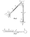
- the anglepoise lamp shown in Figures 4 to 6 is of generally similar construction to that of the first embodiment insofar as it includes a base 1, in this case fashioned as a block, a lower arm 2 having one end pivoted to the base and the other end pivoted to a coupling member 3, an upper arm 4 pivoted by one end to the coupling member 3 and by its other end to a second coupling member 5, and a lamp holder 6 including a shade and bulb holder attached to the member 5.
- the two arms 2, 4 are of identical construction and each comprises a pair of elongate parallel members 30, 31.
- the member 30 is a metal or plastics extrusion and includes a central groove or channel 32 flanked on either side by narrower grooves 33.
- member 30 The ends of member 30 are hinged to the base 1 and to the coupling member 3 by respective pivot pins 35, 36.
- Fixed to the extrusion within the channel 32 and extending over a medial portion of the member 30 is an elongate permanent magnet 38 having continuous pole faces projecting from the channel.
- the second member 31 consists of a channel of ferromagnetic material having connecting tongues 39 fixed to each end. - The side walls of the channel are received in the grooves 33 of member 30 so that the bottom wall of the channel contacts the pole faces of the magnet 38.
- the tongues 39 are connected to the base 1 and to the coupling member 3 by pivot pins 40, 41, the pivots 35, 36, 40, 41 all being parallel so that as the arm 2 is pivoted relative to the base 1 the members 30, 31 are displaced with respect to each other in the longitudinal direction.
- the tongues 39 have slots (not shown) through which the pins 40, 41 pass and along which these pins may travel.
- the magnet and ferromagnetic channel ensure that the members are maintained in firm frictional contact and with sufficient force to retain the arm 2 securely in position between adjustments of the lamp.
- the members 30, 31 of the arm 4 are connected by pivot pins 42 - 45 to the coupling members 3 and 5, the axes of these pins 42 - 45 being parallel to the axes of the pins 35, 36, 40, 41 of the arm 2 so that the arms 2, 4 are adjustable in the same plane.
- the light fitting shown in Figure 7 is of different type to those previously described.
- the lamp holder 60 is carried on a support arm 61 of essentially telescopic construction.
- the arm consists of a first member 62, which is intended to be fixed in any suitable way to a support structure, and a second member 63 consisting of a bar or tube of ferrous metal.
- the lamp holder 61 is attached to one end of member 63 which is somewhat longer than the first member 62.
- Fastened to the member 62 and extending over a major part of its length is a continuous permanent magnet 64 having laterally directed pole pieces against which the member 63 is held by the magnetic forces acting between them.
- the member 63, and hence lamp holder 61, are adjustable in the longitudinal direction of the arm, and the member is held firmly in the adjusted position by the magnetic and friction forces acting between member 63 and the magnet 64.
- guide means such as a tube or the like surrounding the two arm members 62, 63 could be provided to guide the member 63 for longitudinal displacement and to prevent it being pulled away from the magnet 64.
- the members 62, 63 could be formed as channels arranged with their side walls over-lapping and accommodating the magnet between them.
Landscapes
- Engineering & Computer Science (AREA)
- General Engineering & Computer Science (AREA)
- Pivots And Pivotal Connections (AREA)
- Fastening Of Light Sources Or Lamp Holders (AREA)
- Non-Portable Lighting Devices Or Systems Thereof (AREA)
- Endoscopes (AREA)
Applications Claiming Priority (2)
| Application Number | Priority Date | Filing Date | Title |
|---|---|---|---|
| GB8509615 | 1985-04-15 | ||
| GB858509615A GB8509615D0 (en) | 1985-04-15 | 1985-04-15 | Support structure for lamp |
Publications (2)
| Publication Number | Publication Date |
|---|---|
| EP0198706A2 true EP0198706A2 (de) | 1986-10-22 |
| EP0198706A3 EP0198706A3 (de) | 1988-07-27 |
Family
ID=10577665
Family Applications (1)
| Application Number | Title | Priority Date | Filing Date |
|---|---|---|---|
| EP86302773A Ceased EP0198706A3 (de) | 1985-04-15 | 1986-04-14 | Verstellbare Leuchte |
Country Status (4)
| Country | Link |
|---|---|
| EP (1) | EP0198706A3 (de) |
| DK (1) | DK168486A (de) |
| GB (1) | GB8509615D0 (de) |
| NO (1) | NO861451L (de) |
Cited By (1)
| Publication number | Priority date | Publication date | Assignee | Title |
|---|---|---|---|---|
| DE102009037021A1 (de) * | 2009-08-10 | 2011-04-14 | Aaron Rauh | Mehrgliedrige Leuchte |
Family Cites Families (3)
| Publication number | Priority date | Publication date | Assignee | Title |
|---|---|---|---|---|
| US2090439A (en) * | 1932-07-04 | 1937-08-17 | Carwardine George | Equipoising mechanism |
| GB936898A (en) * | 1961-10-18 | 1963-09-18 | William Palmer Iggulden | Improvements in equipoise mechanism |
| DE2223652A1 (de) * | 1972-05-15 | 1973-11-29 | Richard Hassa | Halterung fuer suchscheinwerfer |
-
1985
- 1985-04-15 GB GB858509615A patent/GB8509615D0/en active Pending
-
1986
- 1986-04-14 NO NO861451A patent/NO861451L/no unknown
- 1986-04-14 EP EP86302773A patent/EP0198706A3/de not_active Ceased
- 1986-04-14 DK DK168486A patent/DK168486A/da active IP Right Grant
Cited By (2)
| Publication number | Priority date | Publication date | Assignee | Title |
|---|---|---|---|---|
| DE102009037021A1 (de) * | 2009-08-10 | 2011-04-14 | Aaron Rauh | Mehrgliedrige Leuchte |
| DE102009037021B4 (de) * | 2009-08-10 | 2013-02-28 | Aaron Rauh | Mehrgliedrige Leuchte |
Also Published As
| Publication number | Publication date |
|---|---|
| EP0198706A3 (de) | 1988-07-27 |
| NO861451L (no) | 1986-10-16 |
| DK168486A (da) | 1986-10-16 |
| GB8509615D0 (en) | 1985-05-22 |
| DK168486D0 (da) | 1986-04-14 |
Similar Documents
| Publication | Publication Date | Title |
|---|---|---|
| US6745906B1 (en) | Adjustable width display rack | |
| US5824957A (en) | Electrical cable containment | |
| CA2321343A1 (en) | Linear fixture suspension system | |
| US5154509A (en) | Low voltage magnetic track light system | |
| US4861273A (en) | Low-voltage miniature track lighting system | |
| US4109305A (en) | Relocatable suspended light fixture | |
| US4980808A (en) | Lighting fixture | |
| JP3010540B2 (ja) | エネルギ導体用鎖状案内装置 | |
| EP0879195A1 (de) | Klemmmechanismus | |
| DE3582489D1 (de) | Verbindung zwischen zwei mechanisch und elektrisch loesbar miteinander verbundenen teilen insbesondere eines beleuchtungssystems. | |
| JP2001522275A (ja) | ガセット付の装着タブを有する引き出しスライド装着ブラケット | |
| US4985817A (en) | Supporting device for trouble light | |
| EP0198706A2 (de) | Verstellbare Leuchte | |
| EP0278923B1 (de) | Baukastensystem zur Herstellung von Leitungen zur Aufnahme von elektrischen Kabeln und dergleichen | |
| US5860628A (en) | Hanger for supporting light fixtures on a wall-mounted power track | |
| EP0082723A1 (de) | Vorrichtung zur Übertragung der Schwenkbewegung für Lamellenjalousien | |
| US20070002558A1 (en) | Multi-positional track lighting device | |
| AU681681B2 (en) | Arrangement of lamps | |
| US6125909A (en) | Traverse rod assembly | |
| KR880009256A (ko) | 로의 라이닝용 모듈 및 그의 부착용 하드웨어 | |
| US20240167276A1 (en) | Brace for ceiling drop | |
| EP0324176A3 (en) | Light fixture secured under tension between floor and ceiling | |
| GB2196840A (en) | Riser rail assembly for a shower fitting | |
| KR880002010Y1 (ko) | 자전거용 조명장치의 부착구 | |
| KR102657964B1 (ko) | 형상 가변이 가능한 led 조명장치 |
Legal Events
| Date | Code | Title | Description |
|---|---|---|---|
| PUAI | Public reference made under article 153(3) epc to a published international application that has entered the european phase |
Free format text: ORIGINAL CODE: 0009012 |
|
| AK | Designated contracting states |
Kind code of ref document: A2 Designated state(s): BE CH DE FR GB IT LI NL SE |
|
| PUAL | Search report despatched |
Free format text: ORIGINAL CODE: 0009013 |
|
| AK | Designated contracting states |
Kind code of ref document: A3 Designated state(s): BE CH DE FR GB IT LI NL SE |
|
| 17P | Request for examination filed |
Effective date: 19881121 |
|
| 17Q | First examination report despatched |
Effective date: 19891127 |
|
| STAA | Information on the status of an ep patent application or granted ep patent |
Free format text: STATUS: THE APPLICATION HAS BEEN REFUSED |
|
| 18R | Application refused |
Effective date: 19901110 |
|
| RIN1 | Information on inventor provided before grant (corrected) |
Inventor name: HERITAGE, ROBERT |