EP0199012B1 - Bouton pression - Google Patents
Bouton pression Download PDFInfo
- Publication number
- EP0199012B1 EP0199012B1 EP86102200A EP86102200A EP0199012B1 EP 0199012 B1 EP0199012 B1 EP 0199012B1 EP 86102200 A EP86102200 A EP 86102200A EP 86102200 A EP86102200 A EP 86102200A EP 0199012 B1 EP0199012 B1 EP 0199012B1
- Authority
- EP
- European Patent Office
- Prior art keywords
- flange plate
- press stud
- connection according
- male
- stud connection
- Prior art date
- Legal status (The legal status is an assumption and is not a legal conclusion. Google has not performed a legal analysis and makes no representation as to the accuracy of the status listed.)
- Expired - Lifetime
Links
- 238000010168 coupling process Methods 0.000 claims description 36
- 230000008878 coupling Effects 0.000 claims description 33
- 238000005859 coupling reaction Methods 0.000 claims description 33
- 230000008719 thickening Effects 0.000 claims description 18
- 230000002093 peripheral effect Effects 0.000 claims description 12
- 230000003014 reinforcing effect Effects 0.000 claims description 8
- 239000002184 metal Substances 0.000 claims description 7
- 229920003023 plastic Polymers 0.000 claims description 7
- 239000004033 plastic Substances 0.000 claims description 7
- 238000003780 insertion Methods 0.000 claims description 6
- 230000037431 insertion Effects 0.000 claims description 6
- 239000011324 bead Substances 0.000 claims description 5
- 238000005452 bending Methods 0.000 claims description 5
- 239000000463 material Substances 0.000 claims description 5
- 230000000994 depressogenic effect Effects 0.000 claims 1
- 238000000034 method Methods 0.000 description 6
- 230000008569 process Effects 0.000 description 6
- 230000000295 complement effect Effects 0.000 description 5
- 238000004040 coloring Methods 0.000 description 4
- 230000000694 effects Effects 0.000 description 4
- 239000007769 metal material Substances 0.000 description 3
- 230000009471 action Effects 0.000 description 2
- 230000015572 biosynthetic process Effects 0.000 description 2
- 239000011159 matrix material Substances 0.000 description 2
- 238000007142 ring opening reaction Methods 0.000 description 2
- 235000001674 Agaricus brunnescens Nutrition 0.000 description 1
- 238000009825 accumulation Methods 0.000 description 1
- 230000008859 change Effects 0.000 description 1
- 239000003086 colorant Substances 0.000 description 1
- 230000006835 compression Effects 0.000 description 1
- 238000007906 compression Methods 0.000 description 1
- 230000005489 elastic deformation Effects 0.000 description 1
- 230000003993 interaction Effects 0.000 description 1
- 230000003287 optical effect Effects 0.000 description 1
- 238000004080 punching Methods 0.000 description 1
- 238000006748 scratching Methods 0.000 description 1
- 230000002393 scratching effect Effects 0.000 description 1
- 238000000926 separation method Methods 0.000 description 1
Images


Classifications
-
- A—HUMAN NECESSITIES
- A44—HABERDASHERY; JEWELLERY
- A44B—BUTTONS, PINS, BUCKLES, SLIDE FASTENERS, OR THE LIKE
- A44B17/00—Press-button or snap fasteners
- A44B17/0029—Press-button fasteners made of plastics
-
- Y—GENERAL TAGGING OF NEW TECHNOLOGICAL DEVELOPMENTS; GENERAL TAGGING OF CROSS-SECTIONAL TECHNOLOGIES SPANNING OVER SEVERAL SECTIONS OF THE IPC; TECHNICAL SUBJECTS COVERED BY FORMER USPC CROSS-REFERENCE ART COLLECTIONS [XRACs] AND DIGESTS
- Y10—TECHNICAL SUBJECTS COVERED BY FORMER USPC
- Y10T—TECHNICAL SUBJECTS COVERED BY FORMER US CLASSIFICATION
- Y10T24/00—Buckles, buttons, clasps, etc.
- Y10T24/45—Separable-fastener or required component thereof [e.g., projection and cavity to complete interlock]
- Y10T24/45225—Separable-fastener or required component thereof [e.g., projection and cavity to complete interlock] including member having distinct formations and mating member selectively interlocking therewith
- Y10T24/45602—Receiving member includes either movable connection between interlocking components or variable configuration cavity
- Y10T24/45775—Receiving member includes either movable connection between interlocking components or variable configuration cavity having resiliently biased interlocking component or segment
-
- Y—GENERAL TAGGING OF NEW TECHNOLOGICAL DEVELOPMENTS; GENERAL TAGGING OF CROSS-SECTIONAL TECHNOLOGIES SPANNING OVER SEVERAL SECTIONS OF THE IPC; TECHNICAL SUBJECTS COVERED BY FORMER USPC CROSS-REFERENCE ART COLLECTIONS [XRACs] AND DIGESTS
- Y10—TECHNICAL SUBJECTS COVERED BY FORMER USPC
- Y10T—TECHNICAL SUBJECTS COVERED BY FORMER US CLASSIFICATION
- Y10T24/00—Buckles, buttons, clasps, etc.
- Y10T24/45—Separable-fastener or required component thereof [e.g., projection and cavity to complete interlock]
- Y10T24/45225—Separable-fastener or required component thereof [e.g., projection and cavity to complete interlock] including member having distinct formations and mating member selectively interlocking therewith
- Y10T24/45602—Receiving member includes either movable connection between interlocking components or variable configuration cavity
- Y10T24/45775—Receiving member includes either movable connection between interlocking components or variable configuration cavity having resiliently biased interlocking component or segment
- Y10T24/45874—Receiving member includes either movable connection between interlocking components or variable configuration cavity having resiliently biased interlocking component or segment having axially extending expansion slit along side of cavity
-
- Y—GENERAL TAGGING OF NEW TECHNOLOGICAL DEVELOPMENTS; GENERAL TAGGING OF CROSS-SECTIONAL TECHNOLOGIES SPANNING OVER SEVERAL SECTIONS OF THE IPC; TECHNICAL SUBJECTS COVERED BY FORMER USPC CROSS-REFERENCE ART COLLECTIONS [XRACs] AND DIGESTS
- Y10—TECHNICAL SUBJECTS COVERED BY FORMER USPC
- Y10T—TECHNICAL SUBJECTS COVERED BY FORMER US CLASSIFICATION
- Y10T24/00—Buckles, buttons, clasps, etc.
- Y10T24/45—Separable-fastener or required component thereof [e.g., projection and cavity to complete interlock]
- Y10T24/45225—Separable-fastener or required component thereof [e.g., projection and cavity to complete interlock] including member having distinct formations and mating member selectively interlocking therewith
- Y10T24/4588—Means for mounting projection or cavity portion
- Y10T24/45906—Means for mounting projection or cavity portion having component of means permanently deformed during mounting operation
- Y10T24/45911—Means for mounting projection or cavity portion having component of means permanently deformed during mounting operation and formed from or fixedly attached to projection or cavity portion
- Y10T24/45916—Cooperates with detached component of means
Definitions
- the invention relates to a push-button connection of the type specified in the preamble of claim 1.
- the counter-holding members are used on the front side of a piece of clothing and are protected from being scratched by the holding elements during such treatment because they are part of the structural unit with the push-button part and this structural unit is treated and processed separately from the counter-holding element.
- An alternate scratching of the snap fastener parts by their holding elements with a corresponding accumulation of these structural units is irrelevant, because after their fastening, invisible from the outside, these structural units always come to rest on the inside of the garment.
- the invention has recognized that such a connection is not necessary.
- the invention has for its object to develop an inexpensive push button connection of the type mentioned in the preamble of claim 1, which has a great security of engagement of the coupled push button parts, but still requires only a relatively low closing force to bring their complementary coupling surfaces together. This is achieved according to the invention by the measures specified in the characterizing part of claim 1, which have the following special meaning:
- the flange plate designed as a funnel wall is only turned in by a small angle until the central hole formed by the female dome surfaces has widened so that the thickening of the male dome surfaces fits through. All that is required is a small closing force. On the other hand, a considerably greater opening force is required to uncouple the male dome surfaces.
- the funnel wall must be transferred from its initial position, over its flat dead center position, to an opposing protuberance position, which has an opposite conicity to the initial position.
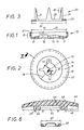
- 1 and 2 is an axial section and a plan view of the component used to form the die part
- Deformation work are performed, which is accordingly reflected in a high opening force.
- a push-button connection is obtained which is easy to close but difficult to open again. This makes handling easier when closing, but the level of security is very high.
- the funnel-shaped lowering finally gives the dome surfaces a centering effect; the male dome surfaces are automatically directed towards the central hole in the female part when pressure is applied.
- the handling of the push button connection is facilitated by the measures of claim 4.
- the dome-like bulge in fact allows high forces to be exerted, which have no risk of deformation on the entire circumferential surface of the counter-member and bring about the desired deformations of the tine ends of the fastening part designed as a toothed ring.
- These measures also have an inventive significance independent of claim 1.
- the counter ring is often enclosed by an ornamental cap, which in turn is made of plastic and can be colored. It is readily possible, as is evident from claim 5, to use a calotte, if necessary, of a much larger dimension than the counter-member. Nevertheless, a uniform coloring of the plastic can be achieved if the central area is formed into a separate cup, in which the counter-member can be accommodated. This results largely in the same wall thicknesses everywhere in the spherical cap, which accordingly allows uniform coloring. For the same reason, the protruding areas of such a large calotte should then be provided with a honeycomb structure.
- the die part 10 consists of a flange plate 11, which is provided with a raised peripheral edge 12, and of a central hole 13 in the flange plate 11 with radial slots 14 extending therefrom, whereby matrix-shaped coupling surfaces are produced in this plate zone.
- the flange plate 11 On the side opposite in the peripheral edge 12, the flange plate 11 has a central funnel-shaped depression 16 in its course, in the middle of which the aforementioned male-shaped coupling surfaces 15 are located.
- the funnel wall 16 is lowered from the front side 17 of the later die part 10. Relative to a plane 18 through the peripheral region of the flange plate 11, which is dash-dotted in FIG. 4 is indicated, the funnel wall 16 extends at an angle of inclination 19.
- the fastening part 20 consists of a so-called "prong ring", the holding elements of which consist of prongs 21, the ends 22 of which, by simple bending, provide the required deformations for fastening purposes.
- the toothed ring 20 is made of a metallic material, namely sheet metal.
- the tines 21 sit on an annular body 23, which in the present case is designed in the shape of a circular ring.
- the toothed ring 20 is produced by punching from the sheet metal material, the tines 21 being cut out in the opening 28 enclosed by the ring body 23 and then being bent out into a position perpendicular to the ring body 23 according to FIG. 3, which characterizes the later use state of the toothed ring 20.
- the annular body 23 has an outer diameter 24 which is less than / equal to the inside width 25 of the raised peripheral edge 12 of the die part 10, that is to say at most the inner diameter of the flange plate 11 is the same.
- the assembly 26 shown in FIG. 4 is now produced from the die part of FIG. 10 and the toothed ring 20 from FIG. 3.
- the ring body 23 is inserted into the interior 27 of the die part 10 and then the circumferential rank 12 is moved into the folded position 12 ′ shown in FIG. 4.
- the die part 10 is consequently provided with its own holding elements 21 from the outset.
- the funnel wall 16 protrudes into the opening 28 of the toothed ring 20 enclosed by the ring body 23.
- a carrier e.g. a garment
- a counter-holding member 33 is positioned on the opposite side 32 of the carrier.
- This in turn consists of a sheet metal body which forms an annular chamber 34 in the circumferential area, the annular opening 35 of which is aligned with the ring of the prongs 21 of the die assembly 26.
- the die assembly 26 is pressed against the counter-holding member 33 with the support 30 lying therebetween.
- the tines 21 drill through the material of the carrier 30 and the tine ends 22 pass through the ring opening 35 into the interior of the ring chamber 34, where they meet the inclined inner ring wall 36 and are therefore bent over.
- the tine ends 22 are rolled into the annular chamber 34 and the desired connection between the die part 10 and the counter-holding member 33 occurs.
- the carrier 30 is provided with the die part 10.
- the shaped sheet metal body of the counter-holding member 33 which is made of metallic material, has in the inner space 37 enclosed by the annular chamber 34 a dome-like bulge 38 which is arched up with respect to the ring opening 35 of the chamber 34 on the opposite side of the counter-holding member 33 and generates a central pressure surface 39 there .
- This pressure surface 39 is initially important for the fastening process of the die assembly 26 because the two parts 26, 33 are pressed against one another.
- the bulge 38 with the pressure surface 39 primarily has the task of effectively exerting manual pressure when it comes to coupling the matrix part 10 to a male part, which will be explained in more detail below.
- the counter-holding member 33 could be used as such, for optical reasons the aim is to cover this metallic sheet metal body 33 towards the face by a cap 40 which can now perform all the decorative functions known per se. It is therefore advisable to produce the spherical cap 40 from plastic material, which can be colored as well as the plastic material of the male part 10 mentioned. In this way, the colors 10, 40 can be matched to the individually used carrier 30.
- the cap 40 is in turn combined with the counter-holding member 33 to form a structural unit 41 indicated in FIG. 5, which can be subjected to the coloring process in this state. Because the prongs 21 are not part of this assembly 41, no scratches or deformations can occur.
- the tines 21 are rather part of the other matrix assembly, which can be colored by itself; scratches on the die part 10 are insignificant because this assembly 26 comes to rest on the rear side 31 of the carrier 30 and is covered in any case by the patrice part 50, which is still to be mentioned.
- FIG. 6 shows an alternative for the formation of a spherical cap 42 which has a dimension which is substantially larger than the diameter 43 shown in FIG. 6.
- the cap 42 is only shown with its inner area in FIG. 6.
- the cap 42 On the underside facing the carrier 30, the cap 42 has a cup 44, which has a clear width 45 which is adapted to the diameter 43 of the counter-holding member 33.
- the structural unit is produced from the calotte 42 and the counter-holding member 33.
- the link 33 is inserted into the interior of the bowl 44 and the bowl walls 46 there are folded over in a manner similar to that of the edge regions 47 of the cap 40 which can be seen in FIG. 5.
- the outer sheet metal walls of the counter-holding member 33 formed around the annular chamber 34 are encompassed .
- the areas 48 lying outside the cup 44 are advantageously provided with a honeycomb structure, of which FIG. 6 shows radial ribs 49.
- the underside of the spherical cap 42 is finally provided with teeth 29 which penetrate into the upper side 32 of the carrier 30 shown in FIG. 5 and thereby secure against rotation unit cause the holding member assembly in which the counter holding member 33 has been equipped with the calotte 42.
- FIG. 7 shows the male part 50 complementary to the female part 10 before it is combined with a corresponding toothed ring 20 to form a male structural unit 56 corresponding to FIG. 4, the analogous appearance of which can best be seen from FIG. 8.
- the male part shown in FIG. 7 also consists of a flange plate 51, which is equipped with an initially angled peripheral edge 52.
- the flange plate 51 is provided coaxially to the male axis 57 indicated by dash-dotted lines in FIG.
- the male part 50 with the prong ring 20 is preassembled to the structural unit 56, in which the male part 50 made of plastic can be colored as well as the corresponding female part 10.
- the male-shaped coupling surface 55 comes into contact with it its head thickening 54 initially against the funnel wall 16.
- the conical outer surface 61 indicated in FIG. 8 on the face side of the die part 10 interacts in a self-centering manner with the head thickening 54; the axis 57 of the male assembly 56 is aligned with the axis 62 of the female assembly 26. It is important that the inclination 63 of the funnel wall 16 indicated in FIG.
- the position of the bending point 66 is indicated in Fig. 10 by a cross.
- the lower perforated edge 65 moves approximately on the circular arc 67 indicated by dashed lines in FIG. 10.
- the outline edge 68 of the head thickening 54 moves approximately on the dashed line 69, which in the following is referred to as "movement line 69" 10
- the funnel wall 16 from its initial position 63, in the rest state must deform by the angle a 1 to an inclined position 63 'in order to let the head thickening 54 pass through on its perforated edge.
- the funnel wall has been deformed up to the deformation layer 16 'indicated by dash-dotted lines in FIG. 10.
- the perforated edge has reached the corresponding position 65 'and lies on the line of movement 69 of the head outline 68 of the male part 50.
- a relatively small closing force P1 is required for this, which is shown in FIG. 1 by a short Arrow is illustrated.
- the head thickening 54 can be passed through the hole 13 in the female part 10 and reaches the coupling position of the male unit 56 in the female unit 26 which can be seen in FIG. 9. Because of the elastic properties of its material, the funnel wall snaps out of it
- the deformation position 16 ′ which can be seen in FIG. 10 returns to its starting position 16 and the head thickening 54 engages behind the funnel wall 16 according to FIG 16, seen in profile section, arrow-shaped.
- the head thickening 54 acts in this arrow shape with its apex region 70 like an "arrowhead".
- the different mode of action of the deformable ring zone 58 when coupling according to FIG. 8 and uncoupling according to FIG. 9 must be noted. Because the holding member assembly 41 already mentioned in connection with FIG. 5 is present on the back of the carrier, the flange plate 51 is stiffened on the back by the counter holding member 33 of FIG. 5 when moving in the insertion direction 64 according to FIG. 8. The ring zone 58 is therefore ineffective in its elasticity.
- the ring zone 58 can be effective in its elasticity.
- the head thickening 54 thereby moves outward in the sense of the axial force arrow 60 shown there. This creates a kind of "snap action" during the uncoupling process. Up to the opening forces P2 there is an axial expansion of the male coupling surfaces 55 in the axial direction 57, without fear of the connection being broken.
- the flange plate 11 is provided with a coaxial groove 75, which is, however, interrupted by radial reinforcing webs 76, which are each arranged in alignment with the radial slots 14 of the matrix-shaped coupling surfaces 15 mentioned.
- the radial slots 14 each lie in the longitudinal center of these reinforcing webs 76.
- the grooves 75 thus form sections 77 which lie on the convex surface side 78 of the funnel wall 16 by means of profiled recesses.
- the groove 75 has, as can be seen from FIG. 12, seen in radial section, a conical opening profile 79, the tip 80 of which faces the aforementioned peripheral edge 12 of the flange plate 11.
- the groove 75 increases the elasticity of the female coupling surfaces 15 when the male coupling surfaces are inserted or removed from the complementary male part.
- By suitably dimensioning the channel and its conical opening profile 79 it is possible to move the above-mentioned closing forces P1 and opening forces P2 into the desired area.
- the reinforcing webs 76 prevent radial notches, which is also caused by the reinforcing beads. Such a bead also serves as wear protection against the end-side thickenings 54 of the male-shaped coupling surfaces 55 of the male part 50 that have been introduced.
Landscapes
- Slide Fasteners, Snap Fasteners, And Hook Fasteners (AREA)
Claims (9)
Applications Claiming Priority (2)
| Application Number | Priority Date | Filing Date | Title |
|---|---|---|---|
| DE19853514896 DE3514896A1 (de) | 1985-04-25 | 1985-04-25 | Druckknopfverbindung |
| DE3514896 | 1985-04-25 |
Publications (3)
| Publication Number | Publication Date |
|---|---|
| EP0199012A2 EP0199012A2 (fr) | 1986-10-29 |
| EP0199012A3 EP0199012A3 (en) | 1987-04-22 |
| EP0199012B1 true EP0199012B1 (fr) | 1990-07-25 |
Family
ID=6269059
Family Applications (1)
| Application Number | Title | Priority Date | Filing Date |
|---|---|---|---|
| EP86102200A Expired - Lifetime EP0199012B1 (fr) | 1985-04-25 | 1986-02-20 | Bouton pression |
Country Status (4)
| Country | Link |
|---|---|
| US (1) | US4751773A (fr) |
| EP (1) | EP0199012B1 (fr) |
| JP (1) | JPS61249402A (fr) |
| DE (2) | DE3514896A1 (fr) |
Families Citing this family (19)
| Publication number | Priority date | Publication date | Assignee | Title |
|---|---|---|---|---|
| DE8710108U1 (de) * | 1987-07-23 | 1987-09-17 | William Prym-Werke GmbH & Co KG, 5190 Stolberg | Verankerungsglied zum Verbinden eines Kurzwaren-Funktionsglieds, insbesondere eines Druckknopfteils, an einem Träger |
| DE4137418C2 (de) * | 1991-11-14 | 1995-07-06 | Stocko Metallwarenfab Henkels | Druckknopf |
| US5870806A (en) * | 1998-03-18 | 1999-02-16 | Black, Jr.; Robert P. | Bistable member for ejecting snap fastener and spring latch assemblies |
| AT411991B (de) | 1998-11-18 | 2004-08-26 | Steco Logistic Gmbh | Behälter aus mehreren platten |
| US6319015B1 (en) | 1999-08-23 | 2001-11-20 | Michael J. Faunce | Garment electrical connector |
| US6854988B2 (en) * | 2002-06-28 | 2005-02-15 | Koninklijke Philips Electronics N.V. | Mechanism for electrically connecting an electronic device to a garment |
| US20070094774A1 (en) * | 2005-10-17 | 2007-05-03 | Sudie Focht | Simple method and apparatus for accessorizing an outfit |
| USD678816S1 (en) | 2010-12-23 | 2013-03-26 | Duraflex Hong Kong Limited | Snap button assembly |
| USD642089S1 (en) * | 2010-12-23 | 2011-07-26 | Duraflex Hong Kong Limited | Portion of a snap button |
| USD665304S1 (en) * | 2011-11-09 | 2012-08-14 | Takeda Seiki, Co., Ltd. | Female part of a snap button |
| USD664891S1 (en) * | 2011-11-09 | 2012-08-07 | Takeda Seiki, Co., Ltd. | Male part of a snap button |
| USD689395S1 (en) | 2012-01-05 | 2013-09-10 | Duraflex Hong Kong Limited | Snap button |
| DE202013001335U1 (de) | 2013-02-11 | 2014-04-14 | Hermann Wursthorn | Druckknopf- Trennelement |
| US9821256B2 (en) | 2014-05-07 | 2017-11-21 | Dv Industries, Llc | Elastically deformable component providing indication of proper fluid filter installation and related methods |
| US20150323401A1 (en) * | 2014-05-07 | 2015-11-12 | Jorge Alejandro Narvaez | Method for Installing an Apparatus to the Correct Torque Setting Without the Use of Torque Measuring Tools |
| USD895346S1 (en) * | 2017-01-25 | 2020-09-08 | Tsann Kuen (Zhangzhou) Enterprise Co., Ltd. | Grill |
| US10609967B2 (en) | 2017-12-20 | 2020-04-07 | Romed Fasteners, Inc. | Magnetic fasteners providing an electrical connection |
| US11172717B2 (en) | 2017-12-20 | 2021-11-16 | Romed Fasteners, Inc. | Magnetic fastener providing electrical connection and having female member with solid cover |
| US11528967B2 (en) * | 2018-11-22 | 2022-12-20 | Ykk Corporation | Male snap button and female snap button |
Family Cites Families (15)
| Publication number | Priority date | Publication date | Assignee | Title |
|---|---|---|---|---|
| DE379746C (de) * | 1923-08-28 | Hans A Roeder | Druckknopf | |
| US1229562A (en) * | 1917-04-03 | 1917-06-12 | William R Willetts | Snap-fastener. |
| US1604020A (en) * | 1924-01-22 | 1926-10-19 | Carr Fastener Co Ltd | Separable fastener |
| US2018635A (en) * | 1933-01-12 | 1935-10-22 | United Carr Fastener Corp | Separable snap fastener |
| US2312441A (en) * | 1941-03-17 | 1943-03-02 | Harold J Reiter | Snap fastener |
| US2256849A (en) * | 1941-03-17 | 1941-09-23 | Patent Button Co | Snap fastener |
| US2759238A (en) * | 1953-06-29 | 1956-08-21 | Scovill Manufacturing Co | Plastic cap for collapsible type snap fastener socket |
| US2933831A (en) * | 1956-11-30 | 1960-04-26 | Tingley Rubber Corp | Rubber footwear with expansion flap |
| DE1435843A1 (de) * | 1964-09-26 | 1969-01-16 | Windmoeller & Hoelscher | Druckknopf |
| US3414949A (en) * | 1967-02-23 | 1968-12-10 | Scovill Manufacturing Co | Snap fastener with removable ornamental button |
| US3416200A (en) * | 1967-03-22 | 1968-12-17 | Scovill Manufacturing Co | Permanently locking snap fastener |
| US3551963A (en) * | 1968-08-16 | 1971-01-05 | Walter W Mosher Jr | Self-locking snap fastener |
| DE2021613A1 (de) * | 1970-05-02 | 1972-02-17 | Prym Werke William | Patrizenhaelfte eines Druckknopfverschlusses mit einem zur Anbringung an einem Traeger dienenden Befestigungskoerper |
| JPS49123476U (fr) * | 1973-02-24 | 1974-10-23 | ||
| DE3336550A1 (de) * | 1983-10-07 | 1985-04-25 | William Prym-Werke Kg, 5190 Stolberg | Druckknopfverbindung an traegerbahnen, insbesondere an kleidungsstuecken |
-
1985
- 1985-04-25 DE DE19853514896 patent/DE3514896A1/de not_active Withdrawn
-
1986
- 1986-02-20 EP EP86102200A patent/EP0199012B1/fr not_active Expired - Lifetime
- 1986-02-20 DE DE8686102200T patent/DE3672875D1/de not_active Expired - Lifetime
- 1986-04-15 JP JP61085237A patent/JPS61249402A/ja active Pending
- 1986-04-23 US US06/855,162 patent/US4751773A/en not_active Expired - Fee Related
Also Published As
| Publication number | Publication date |
|---|---|
| EP0199012A2 (fr) | 1986-10-29 |
| DE3514896A1 (de) | 1986-11-06 |
| EP0199012A3 (en) | 1987-04-22 |
| DE3672875D1 (de) | 1990-08-30 |
| US4751773A (en) | 1988-06-21 |
| JPS61249402A (ja) | 1986-11-06 |
Similar Documents
| Publication | Publication Date | Title |
|---|---|---|
| EP0199012B1 (fr) | Bouton pression | |
| DE68918677T2 (de) | Ostomiekupplung. | |
| AT394896B (de) | Rohrkupplung | |
| DE69912437T2 (de) | Indexierbare dichtung für dampfdruckkocher, und dampfdruckkocher mit einer solchen dichtung | |
| DE3424675C2 (de) | Schlauchkupplung | |
| DE1949238A1 (de) | Zweiteiliger Befestiger | |
| DE2359531C2 (de) | Sicherheitsverschlußkappe für einen Aerosolbehälter | |
| EP1866564B1 (fr) | Dispositif de raccordement pour une conduite de fluide | |
| DE112005001250T5 (de) | Befestigungsklemme | |
| DE3933589A1 (de) | Schlauchkupplung | |
| EP0879004B1 (fr) | Bouton-pression verrouillable | |
| DE69829545T2 (de) | Kupplung mit vergrößerter Rückhaltevorrichtung | |
| DE2723614C3 (de) | Befestigungsvorrichtung mit einer Schraube und einer Schnellspannmutter | |
| DE3706807C2 (de) | Druckknopfteil | |
| DE19731207A1 (de) | Druckknopf | |
| EP0446594A1 (fr) | Fermeture à bouton-pression en deux parties résistante à la traction | |
| DE2922182A1 (de) | Scheibenwischer mit auswechselbarem wischerblatt | |
| DE19547278C2 (de) | Druckknopf | |
| EP0090131B1 (fr) | Tête en plastique pour éléments de fermeture utilisés en mercerie tels que boutons-pression | |
| DE10031729C2 (de) | Steckverbindung zwischen einem ringgewellten Schlauch und einem Glattrohr | |
| DE8916242U1 (de) | Anschlußarmatur für umfangsgerippte Rohre oder Schläuche | |
| DE4137418C2 (de) | Druckknopf | |
| DE9014254U1 (de) | Vorrichtung zum lösbaren Verbinden zweier Bauteile | |
| EP0056428B1 (fr) | Corps en matière élastique pour monter des lattes sur les côtés d'un cadre de lit | |
| DE2854966A1 (de) | Halter fuer geraetesicherungen |
Legal Events
| Date | Code | Title | Description |
|---|---|---|---|
| PUAI | Public reference made under article 153(3) epc to a published international application that has entered the european phase |
Free format text: ORIGINAL CODE: 0009012 |
|
| AK | Designated contracting states |
Kind code of ref document: A2 Designated state(s): DE FR GB IT |
|
| PUAL | Search report despatched |
Free format text: ORIGINAL CODE: 0009013 |
|
| AK | Designated contracting states |
Kind code of ref document: A3 Designated state(s): DE FR GB IT |
|
| 17P | Request for examination filed |
Effective date: 19870713 |
|
| 17Q | First examination report despatched |
Effective date: 19880926 |
|
| ITF | It: translation for a ep patent filed | ||
| GRAA | (expected) grant |
Free format text: ORIGINAL CODE: 0009210 |
|
| AK | Designated contracting states |
Kind code of ref document: B1 Designated state(s): DE FR GB IT |
|
| ET | Fr: translation filed | ||
| GBT | Gb: translation of ep patent filed (gb section 77(6)(a)/1977) | ||
| REF | Corresponds to: |
Ref document number: 3672875 Country of ref document: DE Date of ref document: 19900830 |
|
| ITTA | It: last paid annual fee | ||
| PLBE | No opposition filed within time limit |
Free format text: ORIGINAL CODE: 0009261 |
|
| STAA | Information on the status of an ep patent application or granted ep patent |
Free format text: STATUS: NO OPPOSITION FILED WITHIN TIME LIMIT |
|
| 26N | No opposition filed | ||
| PGFP | Annual fee paid to national office [announced via postgrant information from national office to epo] |
Ref country code: FR Payment date: 19920124 Year of fee payment: 7 Ref country code: DE Payment date: 19920124 Year of fee payment: 7 |
|
| PGFP | Annual fee paid to national office [announced via postgrant information from national office to epo] |
Ref country code: GB Payment date: 19920127 Year of fee payment: 7 |
|
| PG25 | Lapsed in a contracting state [announced via postgrant information from national office to epo] |
Ref country code: GB Effective date: 19930220 |
|
| GBPC | Gb: european patent ceased through non-payment of renewal fee |
Effective date: 19930220 |
|
| PG25 | Lapsed in a contracting state [announced via postgrant information from national office to epo] |
Ref country code: FR Effective date: 19931029 |
|
| PG25 | Lapsed in a contracting state [announced via postgrant information from national office to epo] |
Ref country code: DE Effective date: 19931103 |
|
| REG | Reference to a national code |
Ref country code: FR Ref legal event code: ST |
|
| PG25 | Lapsed in a contracting state [announced via postgrant information from national office to epo] |
Ref country code: IT Free format text: LAPSE BECAUSE OF NON-PAYMENT OF DUE FEES;WARNING: LAPSES OF ITALIAN PATENTS WITH EFFECTIVE DATE BEFORE 2007 MAY HAVE OCCURRED AT ANY TIME BEFORE 2007. THE CORRECT EFFECTIVE DATE MAY BE DIFFERENT FROM THE ONE RECORDED. Effective date: 20050220 |