EP0199080B1 - Cassette pour la manutention d'objets oblongs - Google Patents
Cassette pour la manutention d'objets oblongs Download PDFInfo
- Publication number
- EP0199080B1 EP0199080B1 EP86103639A EP86103639A EP0199080B1 EP 0199080 B1 EP0199080 B1 EP 0199080B1 EP 86103639 A EP86103639 A EP 86103639A EP 86103639 A EP86103639 A EP 86103639A EP 0199080 B1 EP0199080 B1 EP 0199080B1
- Authority
- EP
- European Patent Office
- Prior art keywords
- insert
- lid
- pivotable
- swivel
- container
- Prior art date
- Legal status (The legal status is an assumption and is not a legal conclusion. Google has not performed a legal analysis and makes no representation as to the accuracy of the status listed.)
- Expired - Lifetime
Links
- 238000004519 manufacturing process Methods 0.000 description 2
- 230000005484 gravity Effects 0.000 description 1
- 238000000034 method Methods 0.000 description 1
Images
Classifications
-
- B—PERFORMING OPERATIONS; TRANSPORTING
- B25—HAND TOOLS; PORTABLE POWER-DRIVEN TOOLS; MANIPULATORS
- B25H—WORKSHOP EQUIPMENT, e.g. FOR MARKING-OUT WORK; STORAGE MEANS FOR WORKSHOPS
- B25H3/00—Storage means or arrangements for workshops facilitating access to, or handling of, work tools or instruments
- B25H3/003—Holders for drill bits or the like
Definitions
- the object of the present invention is therefore to propose a generic cassette that is cheaper to manufacture and offers better use of space.
- connection member passes from the cover to the swivel insert remote from the cover and thereby passes through all further swivel inserts.
- the cover Due to the direct connection of the cover with the first swivel insert not adjacent to it, the other connecting elements are completely eliminated. If the cover is swung up, it pulls by means of the connecting link the first swivel insert also with high. The second swivel insert lying between the cover and the first swivel insert is carried along by the first swivel insert. When the cassette is closed, the cover pivots the first pivot element into the container by means of the connecting member and pushes the second pivot element itself.
- two pivoting inserts are arranged so as to be pivotable about a common pivoting axis and have support members in their lower region which abut one another and cause the pivoting inserts to take one another when pivoting up and down.
- a link is movably attached to the lid and to the immediately adjacent swivel insert.
- both swivel inserts on a common swivel axis also has the disadvantage that the elongated objects to be stored in the swivel inserts are no longer directly above the swivel axis when the cassette is open.
- an object for example a larger twist drill
- the torque balance around the pivot axis changes accordingly.
- the lid and the pivoting inserts themselves must be made relatively heavy, which means that they can tip over to prevent the entire cassette, also requires a correspondingly heavy training of the container itself.
- the connecting member preferably extends from the pivot insert remote from the cover through openings in the second pivot insert to the cover. This makes it possible to use the full width of the container in the swivel axis direction for both swivel inserts.
- At least one of the swivel inserts has two parallel rows of storage spaces. This reduces the use of equipment and materials.
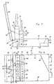
- a cuboid-shaped container 10 has two parallel longitudinal walls 11, 12, two transverse walls 13, 14 perpendicular to it and a bottom 15. Inside the container 10 there is an oblique to the other walls in a corner formed by the longitudinal wall 12 and the transverse wall 13 Oblique wall 16 standing vertically on the floor 15. Two handles 17, 18 are fastened to the transverse wall 12.
- a rectangular cover 20 is articulated on the upper edge of the transverse wall 14. It can be pivoted about a pivot axis 21 which runs adjacent to the upper edge of the transverse wall 14 and is defined by two joints 22, 23. At the end of the cover 20 facing away from the pivot axis 21, a handle 24 is arranged.
- a first pivot insert 30 is located in the vicinity of the transverse wall 14. It can be pivoted about a pivot axis 31 parallel to the pivot axis 21 of the cover 20.
- the pivot axis 31 passes through the longitudinal walls 11 and 12 of the container 10 and can be defined, for example, by rivets.
- the swivel insert 30 is largely cuboid; its extension in the direction of the swivel axis is somewhat less than the length of the transverse walls 13, 14.
- the swivel axis 31 is close to a side of the swivel insert 30 that is rounded in the exemplary embodiment shown in FIGS. 1 and 2.
- the side of the swivel side remote from this rounded side of the Swivel insert 30 is formed by two parallel perforated webs 32, 33 with aligned holes.
- the holes delimit cylindrical storage spaces 34 for elongated objects G.
- the contact surfaces 35 do not extend over the entire width of the swivel insert 30, but instead are each limited to the width of one or more storage spaces 34. They close off individual storage spaces 34 on the side opposite the perforated webs 33.
- a second swivel insert 40 is arranged between the first swivel insert 30 and the transverse wall 14 of the container 10. It can be pivoted about a pivot axis 41 parallel to the pivot axes 21 and 31, which, like the pivot axis 31, passes through the longitudinal walls 11, 12, but closer to its upper edge than the pivot axis 31.
- the second pivot insert 40 is configured similarly to the first pivot insert 30. It has on the side remote from the axis two parallel perforated webs 42, 43 with holes that delimit cylindrical storage spaces 44, and in the area near the axis, contact surfaces 45 parallel to it the perforated webs 42, 43.
- the walls of the second pivot insert 40 which are parallel to the pivot axis 41 and perpendicular to the perforated webs 42, 43 have openings 46 in the central region (indicated schematically in FIG. 2).
- the longitudinal walls 11, 12 have lugs 19 bent into the container 10 at the same distance from the transverse wall 14 above the pivot axis 41 and between the pivot axis 41 and the transverse wall 14.
- the lugs 19 lie on the wall of the cross wall 14 facing Swivel insert 40 on.
- a connecting member 50 connects the cover 20 to the first pivot insert 30.
- the connecting member 50 consists of a U-shaped wire piece, the legs of which extend parallel through the opening 46 in the second pivot insert 40 perpendicular to the pivot axis 41, run out as hooks 51 and in eyelets are hooked in the area away from the axis on the side of the first swivel insert 30 facing the cover 20.
- the base of the connecting member 50 connecting the two legs of the wire piece is guided through a notch 25 in the cover 20.
- the two legs each lead exactly through spaces between two storage spaces 44 through the second swivel insert 40. They enclose one of the storage spaces 44 between them.
- objects G are inserted through the holes in the perforated webs 32, 33 and 42, 43 into the storage spaces 34, 44 in the swivel inserts 30, 40 when the cassette is open.
- the elongated objects G in the illustration twist drills, stand with their lower ends on the contact surfaces 35 and 45.
- the lid 20 is closed by means of the handle 24, i.e. pivoted about the pivot axis 21 (to the right in Fig. 1).
- the connecting member 50 thereby pivots the first pivot insert 30 in the same direction of rotation and the pivot axis 31.
- the second pivot insert 40 initially remains stationary until the inside of the cover 20 abuts against its upper edge or against the objects G inserted into it.
- a further pivoting of the lid 20 also takes the second pivoting insert 40 with it and pivots it about the pivoting axis 41.
- the two pivoting inserts 30, 40 lie one above the other in the container 10.
- the inclined wall 16 prevents shorter, If the cassette is shaken, objects G to be inserted into storage spaces 34, 44 adjacent to side wall 12 slide out of swivel inserts 30, 40.
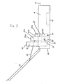
- the connecting member 50 pulls the first swivel insert 30 with it while the cover 20 is folded up about the swivel axis 21. The latter swivels about the swivel axis 31.
- the second swivel insert 40 lying above the first swivel insert 30 is taken along and swiveled about its swivel axis 41. This process continues until the second swivel insert 40 bumps against the lugs 19 on the longitudinal walls 11, 12. This happens when both swivel inserts 30, 40 and the objects G inserted into them are vertical. At this moment, the cover 20 is already somewhat beyond its vertical position, the opening angle of the cassette is approximately 100 °.
- the connector 50 holds the lid 20 and prevents it from opening further.
- the cover 20 pulls on the first swivel insert 30 by means of the connecting member 50.
- the weight of the cover 20 thus prevents the swivel inserts 30, 40 from tipping over unintentionally and the cassette closing itself.
- the objects G are now available for use and can be removed from the swivel inserts 30.40. Since they are essentially exactly above the pivot axes 31, 41, no change in the torque balance occurs when the objects G are removed or inserted.
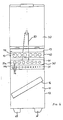
- FIGS. 3 and 4 largely corresponds to the first, described above.
- the main differences are in the design of the swivel inserts 30 and 40.
- the first swivel insert 30 remote from the cover has four parallel perforated webs 32a, 32b, 33a, 33b on its side remote from the axis, two of which are arranged one above the other and have aligned holes. As a result, two parallel rows of holes are formed, which accordingly delimit two parallel rows of cylindrical storage spaces 34 for the elongated objects G.
- Each of the two rows of storage rooms 34 contact areas 35 are assigned.
- An intermediate wall 37 is provided here between the two rows perpendicular to the contact surfaces 35.
- the second swivel insert 40 is each adjacent to a projection 47 and provided parallel to the longitudinal walls 11 and 12.
- the pivot axis 41 runs through these projections 47.
- the operation when opening and closing the cassette corresponds to that of the first embodiment.
- the objects G are not all above the pivot axes 31, 41 in the open position.
Landscapes
- Engineering & Computer Science (AREA)
- Mechanical Engineering (AREA)
- Purses, Travelling Bags, Baskets, Or Suitcases (AREA)
- Packaging Of Annular Or Rod-Shaped Articles, Wearing Apparel, Cassettes, Or The Like (AREA)
- Details Of Rigid Or Semi-Rigid Containers (AREA)
Claims (7)
- Coffret de stockage d'objets oblongs, en particulier d'outils comme des forets hélicoïdaux, etc., présentant :a) un récipient en forme de parallélépipède rectangle (10),b) un couvercle (20), qui peut être basculé, pour le récipient,c) un premier élément pivotant (30) qui est éloigné du couvercle, qui est situé dans le récipient pour la réception des objets, qui est monté de façon à pouvoir pivoter autour d'un axe de rotation (31) parallèle à l'axe de rotation (21) du couvercle et s'étendant au travers du récipient et qui peut être basculé automatiquement lors de l'ouverture du couvercle,d) au moins un second élément pivotant (40), pour la réception des objets, qui est agencé entre le couvercle (20) et le premier élément pivotant (30) dans la zone de pivotement de ces deux derniers et qui est monté de façon à pouvoir pivoter autour d'un axe de rotation (41) parallèle à l'axe de rotation (21) du couvercle et s'étendant au travers du récipient, ete) au moins un élément de liaison (50) entre éléments pivotants et couvercle,caractérisé en ce que l'élément de liaison (50) passe du couvercle (20) à l'élément pivotant (30) éloigné du couvercle et passe alors tous les autres éléments pivotants (40).
- Coffret suivant la revendication 1, caractérisé en ce que les parois latérales (11, 12) du coffret (10) présentent des saillies (19) qui sont en appui sur la face tournée vers le couvercle (20) du second élément pivotant (40), lorsque le second élément pivotant (40) est dressé.
- Coffret suivant l'une ou l'autre des revendications 1 et 2, caractérisé en ce que l'élément de liaison (50) s'étend du premier élément pivotant (30) au couvercle (20), au travers d'ouvertures (46) dans le second élément pivotant (40).
- Coffret suivant la revendication 3, caractérisé en ce que l'élément de liaison (50) s'étend au travers d'espaces intermédiaires qui sont agencés dans les éléments pivotants (30, 40) entre des espaces de stockage (34, 44) des objets oblongs (G).
- Coffret suivant la revendication 4, caractérisé en ce que l'élément de liaison (50) consiste en un fil métallique plié en forme de U dont les branches (51, 52) s'étendent parallèlement l'une à l'autre et perpendiculairement aux axes de rotation (21, 31, 41).
- Coffret suivant l'une quelconque des revendications précédentes, caractérisé en ce que l'élément de liaison (50) est articulé sur le côté, tourné vers le couvercle (20), du premier élément pivotant (30).
- Coffret suivant l'une quelconque des revendications précédentes, caractérisé en ce qu'au moins un des éléments pivotants (30, 40) présente deux rangées parallèles d'espaces de stockage (34, 44).
Applications Claiming Priority (2)
| Application Number | Priority Date | Filing Date | Title |
|---|---|---|---|
| DE8512275U | 1985-04-25 | ||
| DE8512275U DE8512275U1 (de) | 1985-04-25 | 1985-04-25 | Kassette zur Aufbewahrung länglicher Gegenstände |
Publications (3)
| Publication Number | Publication Date |
|---|---|
| EP0199080A2 EP0199080A2 (fr) | 1986-10-29 |
| EP0199080A3 EP0199080A3 (en) | 1987-09-02 |
| EP0199080B1 true EP0199080B1 (fr) | 1991-07-03 |
Family
ID=6780365
Family Applications (1)
| Application Number | Title | Priority Date | Filing Date |
|---|---|---|---|
| EP86103639A Expired - Lifetime EP0199080B1 (fr) | 1985-04-25 | 1986-03-18 | Cassette pour la manutention d'objets oblongs |
Country Status (2)
| Country | Link |
|---|---|
| EP (1) | EP0199080B1 (fr) |
| DE (2) | DE8512275U1 (fr) |
Cited By (3)
| Publication number | Priority date | Publication date | Assignee | Title |
|---|---|---|---|---|
| USD520744S1 (en) | 2004-02-18 | 2006-05-16 | Black & Decker Inc. | Storage container |
| US7165674B2 (en) | 2004-02-18 | 2007-01-23 | Black & Decker Inc. | Storage container |
| DE102005004253B4 (de) * | 2005-01-28 | 2013-11-07 | Peter Rösler | Kassette zur Aufnahme länglicher Gegenstände |
Families Citing this family (5)
| Publication number | Priority date | Publication date | Assignee | Title |
|---|---|---|---|---|
| DE59004762D1 (de) * | 1989-10-27 | 1994-04-07 | Knoblauch Georg Fa | Blechkassette zur Aufnahme von Werkzeugen. |
| DE4325390C2 (de) * | 1993-07-29 | 1997-09-04 | Voelkel Gmbh | Werkzeugkassette |
| DE20219460U1 (de) * | 2002-12-10 | 2003-03-06 | Adolf Würth GmbH & Co. KG, 74653 Künzelsau | Kassette |
| US7328796B2 (en) | 2005-04-25 | 2008-02-12 | Black & Decker Inc. | Tool holder insert for storage container |
| DE102020103319A1 (de) | 2020-02-10 | 2021-08-12 | Adolf Würth Gmbh & Co Kg | Von Deckel einer Werkzeugverwaltungsvorrichtung trennbare Gelenkverbindung an einer Aufnahmevorrichtung für Werkzeugelemente |
Family Cites Families (5)
| Publication number | Priority date | Publication date | Assignee | Title |
|---|---|---|---|---|
| DE8304781U1 (de) * | 1983-06-23 | Fa. Georg Knoblauch, 7928 Giengen | Kassette zur Aufbwahrung länglicher Gegenstände, insbesondere Werkzeuge | |
| US2775342A (en) * | 1955-12-12 | 1956-12-25 | Durex Hardware Mfg Corp | Drill box |
| US3074539A (en) * | 1961-07-12 | 1963-01-22 | Radnor Inc | Container |
| DE7443342U (de) * | 1974-12-28 | 1980-10-30 | Knoblauch Werkzeug | Kassette zur Aufbewahrung laenglicher Gegenstaende insbesondere Werkzeuge |
| GB1551250A (en) * | 1975-06-17 | 1979-08-30 | Parkes & Sons Ltd Benjamin | Boxes for drills or other articles of elongated shape |
-
1985
- 1985-04-25 DE DE8512275U patent/DE8512275U1/de not_active Expired
-
1986
- 1986-03-18 EP EP86103639A patent/EP0199080B1/fr not_active Expired - Lifetime
- 1986-03-18 DE DE8686103639T patent/DE3680017D1/de not_active Expired - Fee Related
Cited By (4)
| Publication number | Priority date | Publication date | Assignee | Title |
|---|---|---|---|---|
| USD520744S1 (en) | 2004-02-18 | 2006-05-16 | Black & Decker Inc. | Storage container |
| USD524046S1 (en) | 2004-02-18 | 2006-07-04 | Black & Decker Inc. | Storage container |
| US7165674B2 (en) | 2004-02-18 | 2007-01-23 | Black & Decker Inc. | Storage container |
| DE102005004253B4 (de) * | 2005-01-28 | 2013-11-07 | Peter Rösler | Kassette zur Aufnahme länglicher Gegenstände |
Also Published As
| Publication number | Publication date |
|---|---|
| EP0199080A3 (en) | 1987-09-02 |
| EP0199080A2 (fr) | 1986-10-29 |
| DE3680017D1 (de) | 1991-08-08 |
| DE8512275U1 (de) | 1985-06-05 |
Similar Documents
| Publication | Publication Date | Title |
|---|---|---|
| DE2759598C2 (de) | Trennwandsystem aus mehreren aufrechten Wandelementen und Wandverbindungselementen | |
| EP3294501B1 (fr) | Dispositif de rangement | |
| DE69820898T2 (de) | Griff für geldkassette | |
| DE102007003937B4 (de) | Tragvorrichtung für Stromsammelschienen | |
| EP0476343B1 (fr) | Boîte pour jeux de tournevis | |
| DE3827546C1 (fr) | ||
| EP0199080B1 (fr) | Cassette pour la manutention d'objets oblongs | |
| DE2421969A1 (de) | Offener ablegebehaelter | |
| DE7619140U1 (de) | Kasten fuer bohrer oder andere laengliche gegenstaende | |
| DE3145203A1 (de) | Kassette zur aufnahme von langgestreckten gegenstaenden | |
| DE3511955C2 (fr) | ||
| DE202012102613U1 (de) | Werkzeugkasten | |
| DE2717096C2 (de) | Schrankelement mit einer Kipplade | |
| DE3500569C1 (de) | Kassette zur Aufbewahrung länglicher Gegenstände, insbes. Werkzeuge wie Spiralbohrer | |
| DE4006782A1 (de) | Kassette zur aufbewahrung von gegenstaenden | |
| EP0367168A1 (fr) | Casier à bouteilles | |
| DE2353280C3 (de) | Durch eine Trennwand in Räume unterschiedlicher Größe aufteilbarer Behälter | |
| DE4019487A1 (de) | Kassette zur aufbewahrung von gegenstaenden | |
| EP0474968A1 (fr) | Cassette pour le rangement d'articles | |
| DE9202838U1 (de) | Aufbewahrungsbox für Schraubendrehereinsätze, sogenannte Bits | |
| DE19612148C2 (de) | Kassette zur Aufbewahrung länglicher Gegenstände | |
| DE102016120750A1 (de) | Rollbehälter mit dualer ausrichtung | |
| DE3619237C2 (fr) | ||
| AT365264B (de) | Versetzbare wand | |
| DE1654516C3 (de) | Stapelbox |
Legal Events
| Date | Code | Title | Description |
|---|---|---|---|
| PUAI | Public reference made under article 153(3) epc to a published international application that has entered the european phase |
Free format text: ORIGINAL CODE: 0009012 |
|
| AK | Designated contracting states |
Kind code of ref document: A2 Designated state(s): BE DE FR NL |
|
| PUAL | Search report despatched |
Free format text: ORIGINAL CODE: 0009013 |
|
| AK | Designated contracting states |
Kind code of ref document: A3 Designated state(s): BE DE FR NL |
|
| 17P | Request for examination filed |
Effective date: 19871203 |
|
| 17Q | First examination report despatched |
Effective date: 19890712 |
|
| GRAA | (expected) grant |
Free format text: ORIGINAL CODE: 0009210 |
|
| AK | Designated contracting states |
Kind code of ref document: B1 Designated state(s): BE DE FR NL |
|
| ET | Fr: translation filed | ||
| REF | Corresponds to: |
Ref document number: 3680017 Country of ref document: DE Date of ref document: 19910808 |
|
| PLBE | No opposition filed within time limit |
Free format text: ORIGINAL CODE: 0009261 |
|
| STAA | Information on the status of an ep patent application or granted ep patent |
Free format text: STATUS: NO OPPOSITION FILED WITHIN TIME LIMIT |
|
| 26N | No opposition filed | ||
| PGFP | Annual fee paid to national office [announced via postgrant information from national office to epo] |
Ref country code: FR Payment date: 19950116 Year of fee payment: 10 |
|
| PGFP | Annual fee paid to national office [announced via postgrant information from national office to epo] |
Ref country code: DE Payment date: 19950328 Year of fee payment: 10 |
|
| PGFP | Annual fee paid to national office [announced via postgrant information from national office to epo] |
Ref country code: NL Payment date: 19950331 Year of fee payment: 10 |
|
| PGFP | Annual fee paid to national office [announced via postgrant information from national office to epo] |
Ref country code: BE Payment date: 19950406 Year of fee payment: 10 |
|
| PG25 | Lapsed in a contracting state [announced via postgrant information from national office to epo] |
Ref country code: BE Effective date: 19960331 |
|
| BERE | Be: lapsed |
Owner name: GISBERT BRINKSCHULTE G.M.B.H. & CO. KG Effective date: 19960331 |
|
| PG25 | Lapsed in a contracting state [announced via postgrant information from national office to epo] |
Ref country code: NL Effective date: 19961001 |
|
| PG25 | Lapsed in a contracting state [announced via postgrant information from national office to epo] |
Ref country code: FR Effective date: 19961129 |
|
| NLV4 | Nl: lapsed or anulled due to non-payment of the annual fee |
Effective date: 19961001 |
|
| PG25 | Lapsed in a contracting state [announced via postgrant information from national office to epo] |
Ref country code: DE Effective date: 19961203 |
|
| REG | Reference to a national code |
Ref country code: FR Ref legal event code: ST |