EP0199144A2 - Dispositif de repassage pour un sèche-cheveux - Google Patents
Dispositif de repassage pour un sèche-cheveux Download PDFInfo
- Publication number
- EP0199144A2 EP0199144A2 EP86104349A EP86104349A EP0199144A2 EP 0199144 A2 EP0199144 A2 EP 0199144A2 EP 86104349 A EP86104349 A EP 86104349A EP 86104349 A EP86104349 A EP 86104349A EP 0199144 A2 EP0199144 A2 EP 0199144A2
- Authority
- EP
- European Patent Office
- Prior art keywords
- ironing
- air
- tube
- plate
- air flow
- Prior art date
- Legal status (The legal status is an assumption and is not a legal conclusion. Google has not performed a legal analysis and makes no representation as to the accuracy of the status listed.)
- Granted
Links
Images


Classifications
-
- D—TEXTILES; PAPER
- D06—TREATMENT OF TEXTILES OR THE LIKE; LAUNDERING; FLEXIBLE MATERIALS NOT OTHERWISE PROVIDED FOR
- D06F—LAUNDERING, DRYING, IRONING, PRESSING OR FOLDING TEXTILE ARTICLES
- D06F75/00—Hand irons
- D06F75/30—Hand irons of special external shape or form
Definitions
- the invention relates to an ironing device for a hairdryer according to the preamble of patent claim 1.
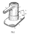
- an ironing device for a hair dryer which has a cover plate with a tube and an ironing plate arranged at a distance from the cover plate. An air flow from a hair dryer is supplied to the ironing plate via a flow channel in the tube for heating. The hair dryer is inserted into the tube of the ironing device and fastened there.
- the heat-conducting ironing plate is heated by the air flow passing through the gap between the cover and ironing plate and can thus be used for ironing when heated.
- the air flow deflected by the ironing plate emerges laterally at the edge of the ironing device between the ironing plate and the cover plate.
- the known ironing device therefore does not require its own heating device for heating the ironing plate, since the ironing plate is heated by the air flow generated by the hair dryer.
- the heater is arranged concentrically in the outer region of the outlet cylinder of the hair dryer.
- the heating therefore does not run over the entire outlet surface of the hair dryer and the central area has no direct heating, because on the one hand a compact construction of the hair dryer is intended and on the other hand the impeller generating the air flow in the outer area of the outlet opening causes the greatest air throughput.
- the compact design of the hair dryer it is necessary to accommodate electronic components in the cooler area in the central region of the outlet cylinder.
- the air stream emerging at the outlet opening of the hair dryer thus has a colder core, which is surrounded by a warm air ring or warm air jacket.
- the air flow impinging on the ironing plate which has a different temperature distribution over the cross section, likewise causes an uneven heating of the ironing plate.
- the ironing plate is then heated somewhat less.
- the bracket plate is also used, as in EP-Bl 0 063 362 and others. also described, has openings in the area of the ironing plate in which the air flow impinges on the ironing plate. The air flow passing through the openings therefore does not heat the material to be ironed as intended over the entire area over which the openings are formed, but rather less in its central area than in the edge area.
- air guiding devices for the air flow are arranged in the area of the ironing device, which directly adjoins the air outlet nozzle of the hair dryer.
- the air flow emerging from the hair dryer with the temperature distribution which is uneven over the cross section is thus swirled and / or deflected according to the invention when passing through this area and a uniform mixing temperature or, as the case may be, the air flow hits the ironing plate.
- a uniform temperature distribution of the air flow in hair dryers can be achieved only with difficulty and with great effort, especially since the flow path of the air flow is much longer when the hair dryer is used to dry the hair than when the hair dryer is used together with the ironing plate as an ironing device, with swirling the air flow when drying hair takes place on the relatively long flow path.
- swirling is advantageously achieved even on the short flow path in the tube of the ironing device.
- the air guiding device is designed as a baffle plate, which is arranged obliquely or transversely to the direction of flow of the air flow.
- the baffle plate is preferably circular and arranged in the middle of the flow channel of the tube.
- the baffle plate essentially has the area of the cold air core of the air flow. The cold air core impinging on the baffle plate is deflected in its direction of flow and strikes the passing, warmer air stream, which leads to a deflection, swirling or mixing.
- the outer air flow is deflected by an annular projection which rotates on the inner wall of the tube.
- the warmer air flow is deflected and hits the colder central core of the air flow, whereupon swirling also takes place.
- the annular projection which reduces the flow cross-section, is preferably formed in that the inner wall of the tube, which runs vertically downward, merges with a concave curvature into the projection which changes the flow direction of the peripheral air envelope. According to this development, a deflection surface changing the flow direction is formed without bulges.
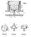
- the size of the baffle plate 16 is dimensioned such that the greatest possible swirling takes place without heat accumulation in the hair dryer 2 and its automatic switch-off responding. That is, the distance between the edge 19 of the bracket plate 16 and the inner wall 25 of the tube is dimensioned such that a sufficient flow can take place.
- the colder air flow KL impinging on the upper side 19 of the baffle plate 16 is thus deflected radially outward in its flow direction and strikes it warmed air flow WL, the flow direction of which is unchanged. Since the flow directions of the colder air flow KL and the heated air flow WL are different from one another, turbulence occurs at the point of intersection. The air flow is thereby mixed and the air flow impinging on the ironing plate 4 has a uniform temperature.
- the mounting height of the baffle plate 16 or the length of the holding foot 17 is dimensioned such that there is also no build-up of heat in the hairdryer 2 and there is sufficient space under the baffle plate 16 so that the swirled air flow impinges on the entire ironing plate 4. That is, the height of the holding foot 17 is dimensioned such that the baffle plate 16 does not shield any area of the bracket plate 4 from the air flow.
- the baffle plate 16 does not shield any area of the bracket plate 4 from the air flow.
- baffle plates 16 show further exemplary embodiments of baffle plates 16.
- the baffle plate 16 has the shape of a cone, the tip of which is directed towards the air flow.
- the surface 21 of the tapered baffle plate 16 can be straight or as shown in Fig. 5B, e.g. be concavely curved.
- 5 C shows a further circular and disk-shaped baffle plate 16, the surface 21 of which is curved concavely or convexly (dashed).
- Baffle plates 16 are also conceivable, which have a different shape and whose basic shape. other cross-sectional shapes of the flow channel 27 are adapted.
- the baffle plate 16 is connected to an outer retaining ring 23 via connecting struts 22.
- the baffle plate 16 shown in FIG. 6, which can have all of the shapes described, can be fastened in a simple manner at a suitable height into the flow channel 27 on the inner wall 25 of the tube 6. Just so the retaining ring 23 can be glued to the lower edge of the outlet opening 28.
- the outer retaining ring 23 can be dispensed with if the connecting struts 22 are resilient and are supported on the inner wall 25 of the tube 6 with a slight excess.
- the free ends of the connecting struts 22 can also be glued to the inner wall 25. If necessary, it is possible to bend long connecting struts 22 for fastening and determining the height of the baffle plate 16 upwards or downwards from the baffle plate.
- the air guiding devices are designed in the form of an annular projection at the edge of the outlet opening 28 of the tube 6.
- the annular projection 24 narrows the passage cross section of the outlet opening 28, the direction of flow of the heated air flow WL now being changed, in deviation from the exemplary embodiment described above.
- it is sufficient to form the projection 24 by attaching a ring to the inner wall 25 of the tube 6.
- the projection 24 can be attached at any suitable height along the tube 6.
- the projection 24 is formed in that the inner wall 25 of the tube 6 extends in the direction of the center of the flow channel 27 via a concavely curved extension.
- the inner wall 25 merges smoothly from the vertical section into the projection 24 due to the concave curvature. There are no bulges that can lead to whistling noises.
- the angle of inclination of the concavely inwardly curved inner wall 25 is chosen so that a suitable change in flow direction of the heated air flow is achieved.
- the change in direction of the air flow WL can be such that it only occurs on the ironing plate 4 with the air flow KL - its flow direction not in this exemplary embodiment was changed - meets.
- the air flow WL meets the air flow KL due to the strong curvature at the outlet opening 28.
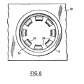
- FIG. 28 shows the projection 24 in the top view into the tube 6.
- the projection 24 has openings 29 in the longitudinal direction of the tube 6.
- the projections 24 thus project into the flow channel 27 as individual teeth.
- the air flow WL can be divided into a proportion which contributes to the swirling of the air flow KL and a proportion which directly on the ironing plate 4 and the breakthroughs 12 hits.
- the 7 also shows a tube section 26, which is aligned in the longitudinal direction of the tube 6 and is shown in dashed lines.
- the pipe section 26 does not touch the projection 24 with its lower end, so that there is an outflow gap 30 for the air flow WL between the lower end of the pipe section 26 and the projection 24.
- the width of the outflow gap 30 is such that there are no whistling noises in the flow velocity of the air flow and the air throughput.
- the pipe section 26 serves to guide the differently tempered air flows and to increase the swirling effect. With the pipe section 26, it is possible to divert the direction of the air flow WL independently of the air flow KL and to supply it to the air flow KL.
- the tube section 26 is as thin-walled as possible and its edges are also rounded.
- the baffle plate 16 described above can also be combined with the pipe section 26.
- water outlet openings not shown, on the edge 19 of the baffle plate 16 or on the projection 24, which are connected to a water reservoir via a hose and a valve.
- the tube 6 or the air guide plate 10 can be used as the water reservoir, for example, which have a double wall for this purpose and form a receptacle.
- the valve can thus be opened as required and, due to the flow conditions at the edge 19 of the baffle plate 16 or the projection 24, water particles are entrained from the water outlet openings.
- the pulling out of the water from the water outlet openings is effected solely by the resulting negative pressure.
- the water taken up in the water reservoir also serves to increase the weight of the ironing device.
Landscapes
- Engineering & Computer Science (AREA)
- Textile Engineering (AREA)
- Cleaning And Drying Hair (AREA)
- Beans For Foods Or Fodder (AREA)
- Drying Of Solid Materials (AREA)
Priority Applications (1)
| Application Number | Priority Date | Filing Date | Title |
|---|---|---|---|
| AT86104349T ATE62718T1 (de) | 1985-04-23 | 1986-03-29 | Buegelvorrichtung fuer einen haartrockner. |
Applications Claiming Priority (2)
| Application Number | Priority Date | Filing Date | Title |
|---|---|---|---|
| DE3514553 | 1985-04-23 | ||
| DE3514553 | 1985-04-23 |
Publications (3)
| Publication Number | Publication Date |
|---|---|
| EP0199144A2 true EP0199144A2 (fr) | 1986-10-29 |
| EP0199144A3 EP0199144A3 (en) | 1989-02-01 |
| EP0199144B1 EP0199144B1 (fr) | 1991-04-17 |
Family
ID=6268843
Family Applications (1)
| Application Number | Title | Priority Date | Filing Date |
|---|---|---|---|
| EP86104349A Expired - Lifetime EP0199144B1 (fr) | 1985-04-23 | 1986-03-29 | Dispositif de repassage pour un sèche-cheveux |
Country Status (3)
| Country | Link |
|---|---|
| EP (1) | EP0199144B1 (fr) |
| AT (1) | ATE62718T1 (fr) |
| DE (1) | DE3678745D1 (fr) |
Cited By (3)
| Publication number | Priority date | Publication date | Assignee | Title |
|---|---|---|---|---|
| GB2255906A (en) * | 1991-03-12 | 1992-11-25 | Allan Joseph Lindsay | A portable hairdryer/utility |
| US6215955B1 (en) * | 1999-04-02 | 2001-04-10 | Liquid Resins International, Ltd. | Heating/dryer system for use in repairing chips in glass |
| GB2380741A (en) * | 2001-10-10 | 2003-04-16 | Shou Mao Chen | Hot air blower iron |
Family Cites Families (2)
| Publication number | Priority date | Publication date | Assignee | Title |
|---|---|---|---|---|
| ES402122A1 (es) * | 1971-06-26 | 1975-03-01 | Azzolini | Perfeccionamientos en planchas electricas que suministran vapor y aire al tejido a planchar. |
| EP0063362B1 (fr) * | 1981-04-18 | 1985-03-27 | Braun Aktiengesellschaft | Fer à repasser électrique |
-
1986
- 1986-03-29 AT AT86104349T patent/ATE62718T1/de not_active IP Right Cessation
- 1986-03-29 EP EP86104349A patent/EP0199144B1/fr not_active Expired - Lifetime
- 1986-03-29 DE DE8686104349T patent/DE3678745D1/de not_active Expired - Fee Related
Cited By (3)
| Publication number | Priority date | Publication date | Assignee | Title |
|---|---|---|---|---|
| GB2255906A (en) * | 1991-03-12 | 1992-11-25 | Allan Joseph Lindsay | A portable hairdryer/utility |
| US6215955B1 (en) * | 1999-04-02 | 2001-04-10 | Liquid Resins International, Ltd. | Heating/dryer system for use in repairing chips in glass |
| GB2380741A (en) * | 2001-10-10 | 2003-04-16 | Shou Mao Chen | Hot air blower iron |
Also Published As
| Publication number | Publication date |
|---|---|
| ATE62718T1 (de) | 1991-05-15 |
| EP0199144B1 (fr) | 1991-04-17 |
| DE3678745D1 (de) | 1991-05-23 |
| EP0199144A3 (en) | 1989-02-01 |
Similar Documents
| Publication | Publication Date | Title |
|---|---|---|
| EP3679199B1 (fr) | Régulateur de jet | |
| DE68922499T2 (de) | Schaumdüsenanordnung. | |
| EP0439781B1 (fr) | Séchoir à cheveux | |
| DE3311579A1 (de) | Waermetauscher | |
| EP0260371A2 (fr) | Sèche-cheveux électrique | |
| EP0063362A1 (fr) | Fer à repasser électrique | |
| DE69324705T2 (de) | Dampfkühler | |
| DE69911484T2 (de) | Haartrockner | |
| WO2017215726A1 (fr) | Dispositif à mèche pour l'évaporation de parfum avec conduit d'écoulement | |
| EP0199144B1 (fr) | Dispositif de repassage pour un sèche-cheveux | |
| DE1931304U (de) | Luftverteiler. | |
| DE2558281A1 (de) | Brenner zur verbrennung von fluessigem brennstoff in gasfoermigem zustand | |
| DE19611450C1 (de) | Vorrichtung zum Erhitzen und Aufschäumen von Milch | |
| DE3605778A1 (de) | Buegelvorrichtung fuer einen haartrockner | |
| DE19914666B4 (de) | Brenner für einen Wärmeerzeuger | |
| EP0536498B1 (fr) | Appareil de chauffage et/ou de refroidissement | |
| EP0695504B1 (fr) | Four pour cuire à la vapeur | |
| DE3115696A1 (de) | Elektrisches buegeleisen | |
| EP0242582B1 (fr) | Bouche à écoulement en spirales | |
| DE1812405C3 (de) | Wirbelbrenner mit einer zentralen öl- und/oder Gaszuführung | |
| DE2854911C2 (fr) | ||
| DE69200335T2 (de) | Drallauslass. | |
| DE4124850A1 (de) | Luftauslass fuer belueftungs- und klimaanlagen | |
| DE4323080C1 (de) | Belüftungsvorrichtung | |
| EP2093333A2 (fr) | Robinetterie de distribution d'eau sanitaire comprenant un dispositif de direction du jet permettant de dévier l'écoulement de l'eau sortant |
Legal Events
| Date | Code | Title | Description |
|---|---|---|---|
| PUAI | Public reference made under article 153(3) epc to a published international application that has entered the european phase |
Free format text: ORIGINAL CODE: 0009012 |
|
| AK | Designated contracting states |
Kind code of ref document: A2 Designated state(s): AT CH DE FR GB IT LI NL SE |
|
| PUAL | Search report despatched |
Free format text: ORIGINAL CODE: 0009013 |
|
| AK | Designated contracting states |
Kind code of ref document: A3 Designated state(s): AT CH DE FR GB IT LI NL SE |
|
| 17P | Request for examination filed |
Effective date: 19890216 |
|
| 17Q | First examination report despatched |
Effective date: 19900821 |
|
| ITF | It: translation for a ep patent filed | ||
| GRAA | (expected) grant |
Free format text: ORIGINAL CODE: 0009210 |
|
| AK | Designated contracting states |
Kind code of ref document: B1 Designated state(s): AT CH DE FR GB IT LI NL SE |
|
| REF | Corresponds to: |
Ref document number: 62718 Country of ref document: AT Date of ref document: 19910515 Kind code of ref document: T |
|
| REF | Corresponds to: |
Ref document number: 3678745 Country of ref document: DE Date of ref document: 19910523 |
|
| GBT | Gb: translation of ep patent filed (gb section 77(6)(a)/1977) | ||
| ET | Fr: translation filed | ||
| PLBE | No opposition filed within time limit |
Free format text: ORIGINAL CODE: 0009261 |
|
| STAA | Information on the status of an ep patent application or granted ep patent |
Free format text: STATUS: NO OPPOSITION FILED WITHIN TIME LIMIT |
|
| PGFP | Annual fee paid to national office [announced via postgrant information from national office to epo] |
Ref country code: AT Payment date: 19920227 Year of fee payment: 7 |
|
| PGFP | Annual fee paid to national office [announced via postgrant information from national office to epo] |
Ref country code: FR Payment date: 19920306 Year of fee payment: 7 |
|
| PGFP | Annual fee paid to national office [announced via postgrant information from national office to epo] |
Ref country code: SE Payment date: 19920316 Year of fee payment: 7 |
|
| PGFP | Annual fee paid to national office [announced via postgrant information from national office to epo] |
Ref country code: NL Payment date: 19920331 Year of fee payment: 7 |
|
| 26N | No opposition filed | ||
| PGFP | Annual fee paid to national office [announced via postgrant information from national office to epo] |
Ref country code: GB Payment date: 19930222 Year of fee payment: 8 |
|
| PGFP | Annual fee paid to national office [announced via postgrant information from national office to epo] |
Ref country code: DE Payment date: 19930226 Year of fee payment: 8 |
|
| PG25 | Lapsed in a contracting state [announced via postgrant information from national office to epo] |
Ref country code: AT Effective date: 19930329 |
|
| PG25 | Lapsed in a contracting state [announced via postgrant information from national office to epo] |
Ref country code: SE Effective date: 19930330 |
|
| PGFP | Annual fee paid to national office [announced via postgrant information from national office to epo] |
Ref country code: CH Payment date: 19930526 Year of fee payment: 8 |
|
| PG25 | Lapsed in a contracting state [announced via postgrant information from national office to epo] |
Ref country code: NL Effective date: 19931001 |
|
| NLV4 | Nl: lapsed or anulled due to non-payment of the annual fee | ||
| PG25 | Lapsed in a contracting state [announced via postgrant information from national office to epo] |
Ref country code: FR Effective date: 19931130 |
|
| REG | Reference to a national code |
Ref country code: FR Ref legal event code: ST |
|
| PG25 | Lapsed in a contracting state [announced via postgrant information from national office to epo] |
Ref country code: GB Effective date: 19940329 |
|
| PG25 | Lapsed in a contracting state [announced via postgrant information from national office to epo] |
Ref country code: LI Effective date: 19940331 Ref country code: CH Effective date: 19940331 |
|
| GBPC | Gb: european patent ceased through non-payment of renewal fee |
Effective date: 19940329 |
|
| REG | Reference to a national code |
Ref country code: CH Ref legal event code: PL |
|
| PG25 | Lapsed in a contracting state [announced via postgrant information from national office to epo] |
Ref country code: DE Effective date: 19941201 |
|
| EUG | Se: european patent has lapsed |
Ref document number: 86104349.5 Effective date: 19931008 |
|
| PG25 | Lapsed in a contracting state [announced via postgrant information from national office to epo] |
Ref country code: IT Free format text: LAPSE BECAUSE OF NON-PAYMENT OF DUE FEES;WARNING: LAPSES OF ITALIAN PATENTS WITH EFFECTIVE DATE BEFORE 2007 MAY HAVE OCCURRED AT ANY TIME BEFORE 2007. THE CORRECT EFFECTIVE DATE MAY BE DIFFERENT FROM THE ONE RECORDED. Effective date: 20050329 |