EP0199181B1 - Kraftstoffeinspritzungssystem für Innenbrennkraftmaschine - Google Patents
Kraftstoffeinspritzungssystem für Innenbrennkraftmaschine Download PDFInfo
- Publication number
- EP0199181B1 EP0199181B1 EP86104805A EP86104805A EP0199181B1 EP 0199181 B1 EP0199181 B1 EP 0199181B1 EP 86104805 A EP86104805 A EP 86104805A EP 86104805 A EP86104805 A EP 86104805A EP 0199181 B1 EP0199181 B1 EP 0199181B1
- Authority
- EP
- European Patent Office
- Prior art keywords
- fuel
- amount
- engine
- point
- injected
- Prior art date
- Legal status (The legal status is an assumption and is not a legal conclusion. Google has not performed a legal analysis and makes no representation as to the accuracy of the status listed.)
- Expired - Lifetime
Links
- 238000002347 injection Methods 0.000 title claims description 120
- 239000007924 injection Substances 0.000 title claims description 120
- 239000000446 fuel Substances 0.000 title claims description 111
- 238000002485 combustion reaction Methods 0.000 title claims description 11
- 238000004364 calculation method Methods 0.000 description 10
- 239000002826 coolant Substances 0.000 description 7
- 230000001052 transient effect Effects 0.000 description 4
- 238000013459 approach Methods 0.000 description 3
- 238000006243 chemical reaction Methods 0.000 description 3
- 230000006835 compression Effects 0.000 description 2
- 238000007906 compression Methods 0.000 description 2
- 238000013213 extrapolation Methods 0.000 description 2
- 238000000034 method Methods 0.000 description 2
- 239000000203 mixture Substances 0.000 description 2
- 230000001133 acceleration Effects 0.000 description 1
- 230000002542 deteriorative effect Effects 0.000 description 1
- 230000000694 effects Effects 0.000 description 1
- 239000002828 fuel tank Substances 0.000 description 1
- 238000013517 stratification Methods 0.000 description 1
- 231100000331 toxic Toxicity 0.000 description 1
- 230000002588 toxic effect Effects 0.000 description 1
Images





Classifications
-
- F—MECHANICAL ENGINEERING; LIGHTING; HEATING; WEAPONS; BLASTING
- F02—COMBUSTION ENGINES; HOT-GAS OR COMBUSTION-PRODUCT ENGINE PLANTS
- F02D—CONTROLLING COMBUSTION ENGINES
- F02D41/00—Electrical control of supply of combustible mixture or its constituents
- F02D41/008—Controlling each cylinder individually
- F02D41/0082—Controlling each cylinder individually per groups or banks
-
- F—MECHANICAL ENGINEERING; LIGHTING; HEATING; WEAPONS; BLASTING
- F02—COMBUSTION ENGINES; HOT-GAS OR COMBUSTION-PRODUCT ENGINE PLANTS
- F02D—CONTROLLING COMBUSTION ENGINES
- F02D41/00—Electrical control of supply of combustible mixture or its constituents
- F02D41/30—Controlling fuel injection
- F02D41/32—Controlling fuel injection of the low pressure type
- F02D41/34—Controlling fuel injection of the low pressure type with means for controlling injection timing or duration
- F02D41/345—Controlling injection timing
-
- F—MECHANICAL ENGINEERING; LIGHTING; HEATING; WEAPONS; BLASTING
- F02—COMBUSTION ENGINES; HOT-GAS OR COMBUSTION-PRODUCT ENGINE PLANTS
- F02B—INTERNAL-COMBUSTION PISTON ENGINES; COMBUSTION ENGINES IN GENERAL
- F02B75/00—Other engines
- F02B75/02—Engines characterised by their cycles, e.g. six-stroke
- F02B2075/022—Engines characterised by their cycles, e.g. six-stroke having less than six strokes per cycle
- F02B2075/027—Engines characterised by their cycles, e.g. six-stroke having less than six strokes per cycle four
-
- Y—GENERAL TAGGING OF NEW TECHNOLOGICAL DEVELOPMENTS; GENERAL TAGGING OF CROSS-SECTIONAL TECHNOLOGIES SPANNING OVER SEVERAL SECTIONS OF THE IPC; TECHNICAL SUBJECTS COVERED BY FORMER USPC CROSS-REFERENCE ART COLLECTIONS [XRACs] AND DIGESTS
- Y02—TECHNOLOGIES OR APPLICATIONS FOR MITIGATION OR ADAPTATION AGAINST CLIMATE CHANGE
- Y02T—CLIMATE CHANGE MITIGATION TECHNOLOGIES RELATED TO TRANSPORTATION
- Y02T10/00—Road transport of goods or passengers
- Y02T10/10—Internal combustion engine [ICE] based vehicles
- Y02T10/40—Engine management systems
Definitions
- the present invention relates to a fuel injection system of a four stroke multicylinder internal combustion engine, comprising: injecting means generating flows of fuel injected into manifold portions of the engine; timing means providing a plurality of timing signals corresponding to at least one position in one engine cycle; first calculating means calculating, in accordance with engine operating conditions, a basic amount of fuel for one engine cycle for a plurality of consecutive injections; memory means storing data of an amount of fuel injected by said injecting means upon receipt of a preceding timing signal; second calculating means calculating a final amount of injected fuel corresponding to a difference between the basic amount of fuel calculated by the first calculating means and a preceding injected amount of fuel stored in the memory; and operating means, responsive to the timing signal from the timing means, operating the injecting means to obtain a final amount of fuel as calculated by the second calculating means to be simultaneously injected into manifold portions.
- Document US-A-4 401 087 discloses a fuel injection system of this type, wherein the amount of fuel to be injected in such an injection cycle can be calculated as twice the basic fuel injection amount subtracted by the finally injected amount during the preceding injection cycle. This means that an injection of fuel of an amount which is short during the preceding injection cycle can be injected in the present cycle to compensate the amount of fuel missing in the preceding cycle. As a result, a desired air fuel ratio can be obtained regardless of the degree of acceleration of the engine.
- the object of the present invention is to provide a fuel injection system for a four stroke multi-cylinder internal combustion engine capable of obtaining an appropriate amount of fuel for injection in the steady state of the engine.
- means correcting the final amount of fuel are provided so that the injected amount of two consecutive fuel injections from said injecting means is equalized in the steady state condition of the engine, by setting said final amount only according to said difference.
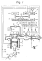
- FIG. 1 schematically illustrates an internal combustion engine provided with a fuel injection system according to the present invention.
- An amount of air passed through an air cleaner 1 is controlled by a throttle valve 3 connected to an accelerator pedal 2.
- the air is introduced, via a surge tank 4, an intake pipe 5, and an intake valve 6, to a combustion chamber 8 of an engine body 7.
- An exhaust gas resultant from the combustion in the combustion chamber 8 is removed, via an exhaust valve 9, by an exhaust pipe 10.
- This engine is, for example, provided with four cylinders, and therefore, four fuel injectors 11-1, 11-2, 11-3, and 11-4 are provided in the respective intake pipes 5 at a position adjacent to the respective intake ports 7a.
- the fuel injectors 11-1, 11-2, 11-3, and 11-4 are divided into first and second groups, wherein the grouping is such that the cylinders belonging to each of the groups have respective operational phases which are spaced at a value of 360 degrees CA.
- the ignition in the cylinders is attained in the order of number #1, #3, #4 and #2 cylinder, during the one complete engine cycle, i.e., 720 degrees CA. Therefore, the first group includes the fuel injectors 11-1 and 11-4 of the first and fourth cylinders, and the second group includes the fuel injectors 11-2 and 11-3 of the second and third cylinders, respectively.
- Reference numeral 12 designates an electronic control circuit as a micro-computer system for attaining the independent group fuel injection operation.
- a fuel pump 13 is connected, via a fuel supply conduit 15, to the fuel injectors 11-1, 11-2, 11-3, and 11-4 for forcibly supplying fuel from the fuel tank 14 to those fuel injectors.
- the electric control circuit 12 as a micro-computer system has, as essential components, a micro-processing unit (MPU) 16, a memory 17 comprised by a read only memory (ROM) and a random access memory (RAM), an input port 18, an output port 19, and a bus 20 interconnecting these elements for transmitting commands and data therebetween.
- MPU micro-processing unit
- ROM read only memory
- RAM random access memory
- a pressure sensor 22 is adapted for providing an analog signal indicating an absolute pressure at the surge tank 4 corresponding to the load of the engine, and a throttle sensor 23 detects the degree of opening of the throttle valve 3.
- the throttle sensor 23 is, for example, constructed as a rotary switch for producing pulse signals, a number of which corresponds to the degree of opening of the throttle valve 3.
- a crank angle sensor 24 detects a position of a crankshaft 27 of the engine, to which is connected a connecting rod 26 connected to a piston 25.
- the crank angle sensor 24 is, for example, constructed as a Hall element facing magnetized teeth members 28 for producing pulse signals. The pulse distance of these pulse signals is utilized to detect the engine speed. These pulse signals are also used as a triggering signal for commencing a fuel injection routine in the control circuit 12.
- a coolant temperature sensor 29 is connected to the engine body 7, in contact with the engine coolant, to provide an analog signal indicating the temperature of the engine coolant.
- the outputs of the pressure sensor 22, throttle sensor 23, and engine coolant temperature sensor 29 are connected to an analog-to-digital converter 21.
- the A/D converter 21 is provided with a multiplexer for sequentially inputting the signals from the analog sensors 22 and 29 for providing digital signals to be input to the input port 18.
- the crank angle sensor 24 is provided with a first output for producing pulse signals for every 30 degrees rotation of the crankshaft 27, and a second output for producing pulse signals for every rotation of the crankshaft 27 of 720 degrees, as shown in Fig. 8-(b) and (c), respectively. These pulse signals are input to the input port 18 via lines 33 and 34, respectively.
- the pulse signal from the throttle sensor 23 is also input to the input port 18.
- the output port 19 is connected to a drive circuit 36 for operating the first group of injectors 11-1 and 11-4 and to a drive circuit 37 for operating the second group of injectors 11-2 and 11-3.
- the MPU 16 operates, in accordance with programs stored in the ROM portion of the memory 17, to calculate fuel injection periods, and to issue signals directed to the drive circuits 36 and 37 for operating the respective groups of fuel injectors (11-1 and 11-4; 11-2 and 11-3 for the calculated periods.
- FIG. 2 illustrates a flow chart for illustrating how the analog-to-digital conversion routine is attained.
- the MPU 16 issues a control signal directed to the A/D converter 21 to select one channel connected to one of the analog sensors, such as the pressure sensor 22, so as to commence the conversion of the analog signal to a digital signal.
- an interruption signal is sent from the A/D converter 21 to the MPU 16 to start an interruption routine as shown in Fig. 2.
- the output data from the A/D converter 21 is read out, and this data is stored in a predetermined RAM area of the memory 17 for storing the intake pressure data.
- a command signal is issued to the A/D converter 21 for selecting the channel connected to the next analog sensor, such as the engine coolant temperature sensor 29, so as to commence to convert the analog signal therefrom to a digital signal.
- Figure 3 shows a routine for calculating a basic fuel injection period. This routine is entered into calculation by an interruption signal from an oscillator or timer counter at a predetermined time interval, such as 2 msec. or 4 msec. At point 40 and 41, the data of the engine speed and intake pressure stored in the RAM areas is read out.
- a basic fuel injection period Tp corresponding to the amount of fuel for two fuel injections from an injector is determined so as to attain the stoichiometric air/fuel ratio.
- the injection period Tp corresponding to the amount of fuel for two fuel injections per single injector is very important for attaining the object of the present invention, as will be fully described later.
- the calculation of the basic injection period Tp is calculated by a map extrapolation method which is, per se, known.
- the ROM area of the memory 17 is provided, as shown by the following Table, with a data map comprised by data of the engine revolution number per one rotation (r.p.m.), D1; data of the intake pressure D2; data of the fuel injection period Tp corresponding to the amount of fuel for two fuel injections per one injector, D3; and numbers of the addresses of the ROM, D4.
- the engine speed data D1 is selected from a value of 400 r.p.m. to 5600 r.p.m. for an interval of 400 r.p.m.
- Ten values of intake pressure P0 to P9 are employed at appropriate intervals. Note; P0 ⁇ P1 ⁇ ... ⁇ P9.
- a fuel injection period Tp is calculated under the two-dimensional extrapolation method in the following way.
- an actual engine speed is 1000 r.p.m. and the value of the actual intake pressure P is between P5 to P6
- the data of the fuel injection periods T15 and T16 is read out from the addresses A + 15 and A + 16 where the data of intake pressure P5 and P6 at 800 r.p.m. is stored.
- the data of the fuel injection periods T25 and T26 are then read out from the addresses A + 25 and A + 26 where the data of the intake pressure P5 and P6 at 1200 r.p.m. is stored. Then, the following calculation is attained.
- the thus calculated basic fuel injection period Tp is stored in a predetermined RAM area of the memory 17.
- the basic fuel injection period T P is corrected by an engine coolant temperature or an intake air temperature in a manner which is, per se, known. The basic value is, for example, corrected so as to increase when the engine coolant temperature is low.
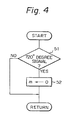
- Figure 4 shows a routine for resetting a counter (m) for discrimination of the group of cylinders designated for the following fuel injection.
- the counter (m) is incremented at every instance when the 30°CA signal, as shown in Fig. 8-(c), is received from the crank angle-sensor 24.
- the crank angle sensor 24 issues pulse signals at every 720 degrees CA of the crankshaft 27, as shown by Fig. 8-(b).
- a discrimination point 51 in Fig. 4 it is judged if the 720°CA signal is now coming. If the judgement is "yes" at point 51, the routine goes to point 52 where the counter (m) is reset.
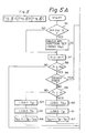
- Figure 5 shows a routine for determining the timing for energizing the fuel injectors 11-1 and 11-4; 11-2 and 11-3, which routine is executed at every interval of 30 degrees CA detected by the crank angle sensor 24.
- the counter (m) is incremented for every 30 degrees CA (step 57) and is cleared by the 720 degrees CA pulse, as already illustrated with reference to Fig. 4. Therefore, the counter (m) has integer values from 0 to 24, as shown in Fig. 8-(d), in one complete engine cycle corresponding to 720 degrees CA.
- the value of 0 or 12 of the counter (m) means, as shown in Fig.
- Xang ((NE x 360°)/60) x (5/1000)
- NE is the engine speed (r.p.m.). Since the injection reference timing should be a multiple of 30 (degrees), Xang/30 is calculated to obtain the quotient X and remainder x.
- the ignition set timing for the injectors 11-1 and 11-4 of the first group measured from the reference position p, i.e., top dead center (TDC) of the first or fourth cylinder at the intake or expansion stroke becomes (6 - X), if the value of (6 - X) is positive. (See Fig. 7.) If the value (6 - X) is negative, the injection set timing q is fixed to zero.
- the injection set timing of the injectors 11-2 and 11-3 of the second group measured from the reference position, i.e., the top dead center of the first or fourth cylinder of the first group during the intake or expansion stroke, becomes (6 - X + 6) since there is a crank angle difference of 180 degrees (180/30 6) in operational phase between the two groups.
- the fuel injection should be completed before the bottom dead center (BDC) of the intake stroke for an angle Xang corresponding to the maximum fuel injection period of, for example, 5 msec. Therefore, the ignition set timing q as a reference point for calculating the ignition signal should be on the point of Xang from the BDC for allowing the fuel injection to be finished before the completion of the intake stroke.
- the distance between the top dead center (TDC) as the reference point p and the bottom dead center (BDC) is 180 degrees CA, corresponding to the value of 6 of the counter (m). Therefore, the injection set timing q measured from the reference position p as the number of the counter m0 becomes 6 - x (x is equal to the quotient of Xang/30).
- the flag F1 is reset (0) when the fuel injection amount calculation for the second group of injectors 11-2 and 11-3, which is once executed for every injection operation of the second group, is attained.
- a "yes" result at point 59 means that the calculation of the final fuel injection period to be effected from now is for the first group of injectors 11-1 and 11-4.
- the program then goes to point 60 where the injected fuel amount Tau at the preceding fuel injection of the second group, Tp1 , is loaded.
- the newest value of the basic fuel injection amount Tp calculated by the routine of Fig. 3 is loaded.
- the final fuel injection amount Tau as the difference Tp - Tp1 is calculated.
- the value of Tau is moved to Tp1 which is used in the following routine for calculating the final fuel injection period of the first group at step 60.
- the flag F1 is set, which means that the injection to be effected from now is for the first group of injectors 11-1 and 11-4.
- the program then flows to point 64 where the injection period Tp2 during the preceding fuel injection of the second group is loaded.
- the newest value of the injection period Tp calculated by the routine of Fig. 3 is loaded.
- a final injection period Tau as a difference Tp - Tp2 is calculated.
- Tau is moved to Tp2.
- the flag F1 is reset, which means that the injection to be effected from now is for the second group of injectors 11-2 and 11-3.
- the routine goes to point 68 where the present time t n is read as a value of a free run counter 47 provided in the control circuit 12.
- the time t i (Fig. 7-(c)) for commencing the fuel injection is calculated. Since 5 msecond is, at maximum, required for reaching the bottom dead center (BDC) in the intake stroke from the injection set timing q, the time t i becomes equal to t n (present time) plus 5 msec. - Tau (final fuel injection period)), as shown in Fig. 7-(c). When 5 ⁇ Tau, the fuel injection start time t i becomes equal to t n .
- compare register 48 provided in the control circuit 12.
- the compare register 48 is provided with a first input connected to the free run counter 47 and second input for receiving the data related to t i .
- Figure 6 shows an interruption routine entering into calculation when, at the compare register 48, the values at the two inputs thereof coincide with each other.
- this interruption routine is for the commencement of the fuel injection.
- the routine goes from point 90 to point 91 where data related to time t e for stopping the fuel injection is loaded.
- the data t e is moved to the corresponding input of the compare register 48.
- the routine from point 93 flows to point 94, where a signal from the input port 19 is input to the drive circuit 36 for opening the injectors 11-1 and 11-4 of the first group.
- injection of the fuel from the first group of injectors 11-1 and 11-4 is started.
- the routine from point 93 flows to point 95, where a signal from the input port 19 is issued to the drive circuit 37 for opening the injectors 11-2 and 11-3 of the second group.
- injection of fuel from the second group of injectors 11-2 and 11-3 is started.
- the routine goes from point 90 to point 96 where the flag F1 is 1.
- the routine goes from point 96 to point 97 where the output port 19 issues a signal to the drive circuit 36 so that the first group of fuel injectors 11-1 and 11-4 are closed. Therefore, fuel injection from the injectors 11-1 and 11-4 is stopped.
- the routine goes to point 98 where the output port 19 issues a signal directed to the drive circuit 37 for closing the second group of injectors 11-2 and 11-3. Therefore, the fuel injection from the second group of injectors 11-2 and 11-3 is stopped.
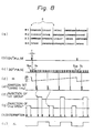
- Figure 8 shows general timing charts illustrating the operation of the present invention.
- Figure 8- (a) shows the change in cycle between the intake, compression, expansion, and exhaust strokes for every cylinder in accordance with the lapse of time.
- Figure 8-(b) shows the pulse signal issued at every crankshaft rotation of 720 degrees CA, corresponding to one complete engine rotation.
- Figure 8-(c) shows the pulse signal issued at every rotation of the crankshaft of 30 degrees CA, wherein g1 shows the first 30 degrees CA signal after the 720 degrees CA signal, and g24 shows the 24th 30 degrees CA signal.
- a time difference f exists between the adjacent 720 degrees CA pulse and the first 30 degrees CA pulse g1.
- Figure 8-(d) illustrates the change in the value of the counter (m).
- Figure 8-(e) shows the ignition set timing m0 for attaining the calculation of the fuel injection amount.
- Figures 8-(f) and (g) show ignition pulse signals for the first and second groups of injectors 11-1 and 11-4; 11-2 and 11-3, respectively.
- Figure 8-(h) shows interruption pulses for commencing the fuel injection and for stopping the fuel injection.
- Figure 8-(i) shows the change in condition of the flag F1.
- the judgement of point 99 is attained by detecting a rate of change of the ratio of the engine speed to the intake air amount, a rate of change in the engine speed, a rate of change in the vehicle speed, or a rate of change of the intake vacuum, and by judging if the rate is larger than a preset value.
- the program goes to the steps after step 100.
- flag F1 is 0, i.e., the injection now to be attained is for the first group.
- Tp1 the injection amount at the preceding injection
- Tp1 is read.
- Tp1 is multiplied by N - 2 and moved to Tp1 , wherein N is an integer larger than 2.
- the value of N determines the rate of compensation of the difference in the injected fuel amount between two adjacent injections. The larger the value N, the faster becomes the rate of compensation.
- N is conveniently expressed by 2 n i.e., as 16 or 32.
- the present invention is not necessarily limited to this value.
- the newest basic fuel amount Tp is read.
- the basic amount is multiplied by N - 1 and moved to Tp.
- Tp - Tp1 is moved to Tau as the final injection amount.
- Tau/N is moved to Tau.
- a final injection period Tau is calculated as a difference between the basic injection amount Tp multiplied by N - 1 and the preceding injected amount Tp1 multiplied by N - 2 averaged by N.
- N - 1 and N - 2 are weight factors for calculating a mean value.
- Taul denotes the first fuel injected amount just after the engine has entered the transient state from the preceding steady state.
- the absolute value of (1 - 2/NJ is smaller than 1, the term (1 - 2/N) i-1 (Taul - Tp/2) approaches zero as the injections are repeated.
- the injected fuel amount Tau finally is equal to Tp/2, and therefore, the amount of fuel for two adjacent injections is equalized during the steady state condition.
- the equalization of the adjacent injections is very advantageous when the two-grouped injection system is employed as in the embodiment.
- the difference between the adjacent injections spaced at 360 degrees would generate a difference in the timing of the finishing of the fuel injections between the adjacent injections, causing a poor stratification of the combustible mixture, deteriorating driveability and increasing toxic emissions.
- the equalization of the fuel injection period between two adjacent injections always allows a synchronization of the finishing timing of two adjacent injections in the corresponding group with the intake stroke. therefore, an intended stratified effect can be realized.
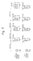
- Figure 9-(b) illustrates the change in the injected amount of fuel Tau as time lapses during the steady state.
- the injected amount Tau is spaced from Tp/2.
- the injected amount approaches Tp/2 as shown by Tau', Tau" and Tau'".
- Figure 10 shows a routine,for calculating a final fuel injection amount in a further embodiment.
- This routine includes, similar to Fig. 5, steps 100 to 102 or 104 to 105 of equalizing the injected amount between the adjacent injections.
- the routine eliminates steps after 99 in Fig. 5 for switching the system for a transient state and steady state.
- the embodiments as illustrated are directed to a four-cylinder internal combustion engine, this invention can be applied to engines having any other number of cylinders, such as a 6-cylinder or 8-cylinder engine.
- the injectors are divided into three groups and the cylinders in each of the groups have a phase difference of 360 degrees CA.
Landscapes
- Engineering & Computer Science (AREA)
- Chemical & Material Sciences (AREA)
- Combustion & Propulsion (AREA)
- Mechanical Engineering (AREA)
- General Engineering & Computer Science (AREA)
- Electrical Control Of Air Or Fuel Supplied To Internal-Combustion Engine (AREA)
Claims (1)
- Brennstoffeinspritzsystem für eine 4-Takt-Mehrzylinder-Brennkraftmaschine, das eine Einspritzvorrichtung, die in Ansaugrohrabschnitte der Maschine eingespritzte Brennstoffströme erzeugt, eine Zeitsteuereinrichtung, die eine Vielzahl von zumindest einer Stelle in einem Maschinenzyklus entsprechenden Zeitsteuersignalen abgibt, eine erste Recheneinrichtung, die für eine Vielzahl aufeinanderfolgender Einspritzungen eine Grundbrennstoffmenge für einen Maschinenzyklus entsprechend den Maschinenbetriebszuständen berechnet, eine Speichereinrichtung, die Daten für eine mittels der Einspritzvorrichtung auf den Empfang eines vorangehenden Zeitsteuersignals hin eingespritzte Brennstoffmenge speichert, eine zweite Recheneinrichtung, die entsprechend einer Differenz zwischen der von der ersten Recheneinrichtung berechneten Grundbrennstoffmenge und einer vorangehend eingespritzten, in der Speichereinrichtung gespeicherten Brennstoffmenge eine endgültig einzuspritzende Brennstoffmenge berechnet, und eine auf das Zeitsteuersignal aus der Zeitsteuereinrichtung ansprechende Betätigungseinrichtung aufweist, die die Einspritzvorrichtung zum Erzielen eines gleichzeitigen Einspritzens einer endgültigen Brennstoffmenge gemäß der Berechnung durch die zweite Recheneinrichtung in Ansaugrohrabschnitte betreibt, gekennzeichnet durch eine Einrichtung (101, 103, 105; 107, 109, 111), die bei gleichbleibendem Laufzustand der Maschine (7) die endgültigen Brennstoffmenge (Tau) durch Einstellen der endgültigen Menge allein entsprechend der Differenz derart korrigiert, daß für zwei aufeinanderfolgende Brennstoffeinspritzungen die von der Einspritzvorrichtung (11-1, 11-2, 11-3, 11-4) eingespritzte Menge gleichgemacht ist.
Applications Claiming Priority (6)
| Application Number | Priority Date | Filing Date | Title |
|---|---|---|---|
| JP7275685A JPS61232357A (ja) | 1985-04-08 | 1985-04-08 | 内燃機関の燃料噴射制御装置 |
| JP72758/85 | 1985-04-08 | ||
| JP72756/85 | 1985-04-08 | ||
| JP7275985A JPS61232359A (ja) | 1985-04-08 | 1985-04-08 | 内燃機関の燃料噴射制御装置 |
| JP72759/85 | 1985-04-08 | ||
| JP7275885A JPS61232358A (ja) | 1985-04-08 | 1985-04-08 | 内燃機関の燃料噴射制御装置 |
Publications (3)
| Publication Number | Publication Date |
|---|---|
| EP0199181A2 EP0199181A2 (de) | 1986-10-29 |
| EP0199181A3 EP0199181A3 (en) | 1987-09-30 |
| EP0199181B1 true EP0199181B1 (de) | 1991-09-25 |
Family
ID=27301033
Family Applications (1)
| Application Number | Title | Priority Date | Filing Date |
|---|---|---|---|
| EP86104805A Expired - Lifetime EP0199181B1 (de) | 1985-04-08 | 1986-04-08 | Kraftstoffeinspritzungssystem für Innenbrennkraftmaschine |
Country Status (3)
| Country | Link |
|---|---|
| US (1) | US4700681A (de) |
| EP (1) | EP0199181B1 (de) |
| DE (1) | DE3681621D1 (de) |
Families Citing this family (10)
| Publication number | Priority date | Publication date | Assignee | Title |
|---|---|---|---|---|
| JPH086585B2 (ja) * | 1987-01-13 | 1996-01-24 | トヨタ自動車株式会社 | 2サイクル内燃機関 |
| JPH0689681B2 (ja) * | 1987-02-18 | 1994-11-09 | トヨタ自動車株式会社 | 2サイクル内燃機関 |
| DE3728118A1 (de) * | 1987-08-22 | 1989-03-02 | Pierburg Gmbh | Verfahren zur steuerung der einspritzphase einer elektronischen brennstoffeinspritzung |
| DE3803952A1 (de) * | 1988-02-10 | 1989-08-24 | Pierburg Gmbh | Verfahren zum betreiben einer elektronisch geregelten brennstoffeinspritzeinrichtung fuer brennkraftmaschinen |
| DE4020654C2 (de) * | 1990-06-29 | 1999-12-16 | Bosch Gmbh Robert | Regelverfahren in Verbindung mit einer Brennkraftmaschine und/oder einem Kraftfahrzeug und Regelvorrichtung zur Durchführung des Regelverfahrens |
| US5137000A (en) * | 1991-03-29 | 1992-08-11 | Cummins Electronics Company | Device and method for decreasing delays in fuel injected internal combustion engines |
| DE59101113D1 (de) * | 1991-09-26 | 1994-04-07 | Siemens Ag | Verfahren zum Steuern einer Brennkraftmaschine während dynamischer Übergangszustände. |
| US6390082B1 (en) * | 2000-07-13 | 2002-05-21 | Caterpillar Inc. | Method and apparatus for controlling the current level of a fuel injector signal during sudden acceleration |
| JP5939119B2 (ja) * | 2012-10-03 | 2016-06-22 | トヨタ自動車株式会社 | 多気筒内燃機関の気筒間空燃比ばらつき異常検出装置 |
| JP5780257B2 (ja) * | 2013-03-22 | 2015-09-16 | トヨタ自動車株式会社 | 多気筒内燃機関の気筒間空燃比ばらつき異常検出装置 |
Family Cites Families (18)
| Publication number | Priority date | Publication date | Assignee | Title |
|---|---|---|---|---|
| JPS5817339B2 (ja) * | 1978-05-12 | 1983-04-06 | 日産自動車株式会社 | 燃料遮断装置 |
| JPS55139941A (en) * | 1979-04-18 | 1980-11-01 | Nissan Motor Co Ltd | Accelerator of cylinder number control engine |
| JPS5654934A (en) * | 1979-10-12 | 1981-05-15 | Nissan Motor Co Ltd | Fuel cut device |
| US4349000A (en) * | 1980-02-11 | 1982-09-14 | Brunswick Corporation | Control means for fuel injection in an internal combustion engine |
| JPS56141025A (en) * | 1980-04-03 | 1981-11-04 | Nissan Motor Co Ltd | Fuel control ling device |
| JPS5726230A (en) * | 1980-07-25 | 1982-02-12 | Toyota Motor Corp | Electronic control type fuel injection method |
| IT1139075B (it) * | 1981-04-06 | 1986-09-17 | Alfa Romeo Auto Spa | Apparato di controllo dell'alimentazione per un motore a c.i. |
| DE3129078A1 (de) * | 1981-07-23 | 1983-02-03 | Daimler-Benz Ag, 7000 Stuttgart | Verfahren zur aussetzregelung einer periodisch arbeitenden brennkraftmaschine |
| JPS58138234A (ja) * | 1982-02-10 | 1983-08-17 | Nissan Motor Co Ltd | 車両用多気筒内燃機関の燃料供給制御装置 |
| JPS58148242A (ja) * | 1982-02-25 | 1983-09-03 | Nissan Motor Co Ltd | 気筒数制御エンジン |
| JPS58200048A (ja) * | 1982-05-18 | 1983-11-21 | Fuji Heavy Ind Ltd | 燃料供給気筒数制御装置 |
| JPS5970846A (ja) * | 1982-10-18 | 1984-04-21 | Toyota Motor Corp | 分割運転制御式内燃機関 |
| JPS5974346A (ja) * | 1982-10-22 | 1984-04-26 | Toyota Motor Corp | 分割運転制御式内燃機関 |
| DE3313038A1 (de) * | 1983-04-12 | 1984-10-18 | Robert Bosch Gmbh, 7000 Stuttgart | Mehrzylinder-brennkraftmaschine mit abschaltbaren zylindergruppen |
| GB2148548B (en) * | 1983-10-20 | 1987-08-05 | Honda Motor Co Ltd | Method of controlling operating amounts of operation control means for an internal combustion engine |
| KR890000500B1 (ko) * | 1983-11-21 | 1989-03-20 | 가부시기가이샤 히다찌세이사꾸쇼 | 내연기관의 공연비 제어장치 |
| JPS60203832A (ja) * | 1984-03-29 | 1985-10-15 | Honda Motor Co Ltd | 内燃エンジンの燃料供給制御方法 |
| US4532907A (en) * | 1984-09-14 | 1985-08-06 | Ford Motor Company | Selective single fire/double fire fuel injection control |
-
1986
- 1986-04-07 US US06/849,176 patent/US4700681A/en not_active Expired - Fee Related
- 1986-04-08 DE DE8686104805T patent/DE3681621D1/de not_active Expired - Lifetime
- 1986-04-08 EP EP86104805A patent/EP0199181B1/de not_active Expired - Lifetime
Also Published As
| Publication number | Publication date |
|---|---|
| EP0199181A2 (de) | 1986-10-29 |
| EP0199181A3 (en) | 1987-09-30 |
| US4700681A (en) | 1987-10-20 |
| DE3681621D1 (de) | 1991-10-31 |
Similar Documents
| Publication | Publication Date | Title |
|---|---|---|
| US5690073A (en) | Fuel injection control device of a multi-cylinder engine | |
| JP2617427B2 (ja) | 4サイクル内燃機関のシリンダにおける順次連続する燃料または点火分配の同期方法 | |
| US5870986A (en) | Fuel injection controlling apparatus in starting an internal combustion engine | |
| US5265575A (en) | Apparatus for controlling internal combustion engine | |
| US4528960A (en) | Fuel injection mode control for multi-cylinder internal combustion engine | |
| GB2217045A (en) | Fuel injection control system for an automotive engine | |
| US4495924A (en) | Fuel injection control system for a direct injection type internal combustion engine | |
| US4448171A (en) | Method and apparatus for optimum control of internal combustion engines | |
| US4700681A (en) | Fuel injection system for an internal combustion engine | |
| US4984552A (en) | Fuel injection device for an internal combustion engine | |
| US4527529A (en) | Method and apparatus for controlling fuel injection for an internal combustion engine | |
| US5156128A (en) | Apparatus for controlling variation in torque of internal combustion engine | |
| JPH06280660A (ja) | エンジンの燃料制御装置 | |
| JP3191676B2 (ja) | 内燃機関の点火時期制御装置 | |
| US4725954A (en) | Apparatus and method for controlling fuel supply to internal combustion engine | |
| JP2917600B2 (ja) | 内燃機関の燃料噴射制御装置 | |
| US4644784A (en) | Suction pipe pressure detection apparatus | |
| US4502448A (en) | Method for controlling control systems for internal combustion engines immediately after termination of fuel cut | |
| EP0160949A2 (de) | Verfahren und Gerät zur Steuerung des Luft-Kraftstoffverhältnisses in einer Innenbrennkraftmaschine mit sequentieller Kraftstoffeinspritzung | |
| JPS6318766Y2 (de) | ||
| GB2342447A (en) | Verifying engine cycle of an injection IC engine | |
| GB2121215A (en) | Automatic control of the fuel supply to an internal combustion engine immediately after termination of fuel cut | |
| JPH029172B2 (de) | ||
| JP2774018B2 (ja) | 多気筒内燃機関の燃料噴射制御装置 | |
| US4892077A (en) | Fuel injection control method for internal combustion engines |
Legal Events
| Date | Code | Title | Description |
|---|---|---|---|
| PUAI | Public reference made under article 153(3) epc to a published international application that has entered the european phase |
Free format text: ORIGINAL CODE: 0009012 |
|
| 17P | Request for examination filed |
Effective date: 19860408 |
|
| AK | Designated contracting states |
Kind code of ref document: A2 Designated state(s): DE |
|
| PUAL | Search report despatched |
Free format text: ORIGINAL CODE: 0009013 |
|
| AK | Designated contracting states |
Kind code of ref document: A3 Designated state(s): DE |
|
| 17Q | First examination report despatched |
Effective date: 19880701 |
|
| GRAA | (expected) grant |
Free format text: ORIGINAL CODE: 0009210 |
|
| AK | Designated contracting states |
Kind code of ref document: B1 Designated state(s): DE |
|
| REF | Corresponds to: |
Ref document number: 3681621 Country of ref document: DE Date of ref document: 19911031 |
|
| PLBE | No opposition filed within time limit |
Free format text: ORIGINAL CODE: 0009261 |
|
| STAA | Information on the status of an ep patent application or granted ep patent |
Free format text: STATUS: NO OPPOSITION FILED WITHIN TIME LIMIT |
|
| 26N | No opposition filed | ||
| PGFP | Annual fee paid to national office [announced via postgrant information from national office to epo] |
Ref country code: DE Payment date: 19960418 Year of fee payment: 11 |
|
| PG25 | Lapsed in a contracting state [announced via postgrant information from national office to epo] |
Ref country code: DE Free format text: LAPSE BECAUSE OF NON-PAYMENT OF DUE FEES Effective date: 19980101 |