EP0199182B1 - Réglette commutable - Google Patents
Réglette commutable Download PDFInfo
- Publication number
- EP0199182B1 EP0199182B1 EP86104828A EP86104828A EP0199182B1 EP 0199182 B1 EP0199182 B1 EP 0199182B1 EP 86104828 A EP86104828 A EP 86104828A EP 86104828 A EP86104828 A EP 86104828A EP 0199182 B1 EP0199182 B1 EP 0199182B1
- Authority
- EP
- European Patent Office
- Prior art keywords
- cover
- lever
- switchable
- connecting block
- block arrangement
- Prior art date
- Legal status (The legal status is an assumption and is not a legal conclusion. Google has not performed a legal analysis and makes no representation as to the accuracy of the status listed.)
- Expired - Lifetime
Links
- 239000003973 paint Substances 0.000 claims 1
- 238000000034 method Methods 0.000 description 3
- 238000005516 engineering process Methods 0.000 description 2
- 238000009434 installation Methods 0.000 description 2
- 238000004519 manufacturing process Methods 0.000 description 2
- 238000000926 separation method Methods 0.000 description 2
- 208000029152 Small face Diseases 0.000 description 1
- 238000006243 chemical reaction Methods 0.000 description 1
- 230000001681 protective effect Effects 0.000 description 1
Images


Classifications
-
- H—ELECTRICITY
- H01—ELECTRIC ELEMENTS
- H01H—ELECTRIC SWITCHES; RELAYS; SELECTORS; EMERGENCY PROTECTIVE DEVICES
- H01H31/00—Air-break switches for high tension without arc-extinguishing or arc-preventing means
- H01H31/02—Details
- H01H31/12—Adaptation for built-in fuse
- H01H31/122—Fuses mounted on, or constituting the movable contact parts of, the switch
-
- H—ELECTRICITY
- H01—ELECTRIC ELEMENTS
- H01H—ELECTRIC SWITCHES; RELAYS; SELECTORS; EMERGENCY PROTECTIVE DEVICES
- H01H21/00—Switches operated by an operating part in the form of a pivotable member acted upon directly by a solid body, e.g. by a hand
- H01H21/02—Details
- H01H21/16—Adaptation for built-in fuse
- H01H21/165—Fuses mounted on, or constituting the movable contact parts of, the switch
Definitions
- the invention relates to a switchable bar, consisting of a lower part with attached side parts and with connections for busbars, from a front or side mounted outlet and a shift lever, which is designed as an angle lever with a first lever arm and a second lever arm and connecting and Has guide elements of a switching mechanism.
- a switchable bar is already known from DE 23 38 982 A1 and is used primarily in the low voltage technology.
- Switchable strips usually have the shape of elongated cuboids and essentially consist of a lower part, two side walls, a cover, a switching mechanism and power connections and contacts inside the cuboid, as well as a switch lever that can be actuated from the outside and can be moved in the longitudinal direction of the cuboid.
- On one of the small faces of the cuboid are the connections - also called "outlet" in technical terms - for the respective consumer.
- the opposite end face generally remains open or is given a protective cover.
- Such a switchable bar is mounted transversely on busbars running generally horizontally on a wall. When the switchable bar is actuated by means of the switch lever, it is moved in the vertical direction. Relevant safety regulations require that the contacts inside the switchable bar are closed when the switch lever is up (switch position "on”), and that the switch contacts inside the switchable bar are open when the switch lever is down switch position "off”) .
- the position of the outlet (above or below) is also fixed and can not be changed by turning the switchable bar by 180 °, since in this case the on / off position of the switch lever would violate the safety regulations. After such a 180 ° rotation, the position of the outlet has been changed from top to bottom or vice versa, without the on / off position of the shift lever being changed thereby.
- switchable strips are known in which the outlet can be changed from top to bottom or vice versa, but the associated conversion measures are time-consuming and cumbersome.
- Switchable strips are also known, in which fuse links or contact blades are attached to the cover, which is lifted from the side parts when the strip is switched off or is placed on the side parts when the strip is switched on, but the position of the outlet can also be used for these strips cannot be changed easily.
- a cover with fuse inserts or contact blades arranged thereon can be separated from the lower part and the side parts, the lever arms are rotatably fastened at their connection point via a web on the cover, that part of the switching mechanism of the cover or the angle lever connecting and Has guide elements, the counterparts attached to the lower part or on the side parts as well as all other connecting parts arranged on the lower part or on the side parts to the cover are formed symmetrically with respect to a 180 ° rotation about an axis of symmetry which runs perpendicular to the cover plane.
- Such a switchable strip has the advantage over all previously known switchable strips that after a separation of the cover with the parts attached to it from the lower part and the attached side parts the latter are rotated by 180 ° relative to the cover and because of their rotational symmetry with the cover and the attached parts can be put together.
- the outlet connection can be attached on the front (one side) or on the side.
- the counterparts of the switching mechanism consist of slots, grooves and bulges which are essentially perpendicular to the cover plane and are open on the cover side and which are substantially perpendicular to the cover parts engage the corresponding cams or pins of the angle lever or connecting pieces attached to the cover as connecting and guiding elements.
- This arrangement of the switching mechanism on the side parts has the further advantage that there is enough space inside the switchable bar, especially in the area of the switching mechanism, for the fuse links, contact springs and connecting elements, so that the installation width of the switchable bar is kept comparatively small.
- a further advantageous embodiment of the invention consists in further grooves parallel to the grooves of the switching mechanism, in which guide webs attached to the cover can slide, which, when the switching lever is actuated, reduce tilting of the cover with respect to the side parts and the lower part.
- the angle lever is designed as a double lever and thus consists of two angle levers constructed in mirror image to one another, which are connected to one another at the free end of the second lever arm by a handle.
- This handle advantageously has the form of a rod, tube or open profile.
- all other parts of the switching mechanism are expediently constructed in mirror image of one another. The one when actuated the forces acting on the gearshift lever are thus transmitted evenly to both side parts and the cover, which engages in a corresponding manner via two opposite connecting webs with pins located thereon in the opposite, matching bores of the angle lever designed as a double lever.
- the two opposite angle levers are advantageously arranged on the inside of the side parts.
- Each angle lever has a cam at the free end of its first lever arm, which is slidably arranged in a groove parallel to the slot mentioned and / or in a bulge arranged perpendicular to it.
- the angle between the lever arms of the bell crank is defined as the angle between the connecting lines cam center-pin center and pin center-center point of the handle attachment. This angle is advantageously in the range between 80 and 120 ° and is preferably 100 °.
- the recesses on the lid edges can also serve as stops for the second lever arm.
- the stops are expediently chosen so that when one stop the center of the cam is located further away from the cover than the center of the pin, while at the other stop the center of the cam is closer to the cover than the center of the pin. It is advantageous to ensure at the same time that the angle between the first lever arm and the plane perpendicular to the groove and slot at the first stop corresponds to the value at which the cams and pins can slide in their groove or slot at the same time; while at the second stop this angle is smaller so that the cam must be in the bulge.
- the length of the connecting web on the cover is to be chosen so that the cover just lies on the side parts at the second stop.
- the switch-off process takes place as follows: The bar is initially switched on. The cover rests on the side parts, the contact blades of the fuse links are inserted into the corresponding contact springs, and the cam of the first lever arm is located in the bulge of the side part. If a force now acts on the double lever parallel to the cover level and in the longitudinal direction of the switchable bar, this is acted on by a torque with respect to an axis perpendicular to the plane of the side parts, which runs through the support points of the two opposite cams in the bulges of the side parts. A rotation of the angle lever about this axis is at the same time a rotation of the angle lever about the center of the pin relative to the cover. The distance of the cam from the cover changes.
- the switch-on process takes place in reverse.
- the force on the shift lever acts in the opposite direction and causes a torque on the angle lever.
- the support point of the cam and thus the axis of rotation are now on the opposite side of the bulge.
- the bulge is somewhat wider than the groove and the diameter of the cam. This ensures that at the beginning of the switching-on process the cam does not get into the groove above the bulge and is then no longer rotatable, but instead is immediately moved into the bulge and is supported on the upper side thereof.
- a catch is attached to the cover, into which a cam arranged on the second lever arm can snap. Since at this tee the cam of the first lever arm and the pin can slide simultaneously in the cover-side groove or in the cover-side slot, in this position the cover with the parts attached to it, i.e. be separated from the side parts with the fuse links and the double lever, the angle lever being held in this position by the catch.
- this detent is designed as a double detent, the normal "off" position of the switchable bar being given when the detent cam of the second lever arm rests in the first detent, at which the angle of the first lever arm relative to the groove and Slot vertical plane is smaller than the angle at which the cam of the first lever arm and the pin can slide simultaneously in the groove or in the slot. Only when the locking cam of the second lever arm rests in the second locking, is this angle so large that the cover with the parts attached to it can be separated from the side parts.
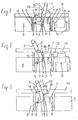
- FIG. 8 shows the U-shaped cross-section of the switchable bar with the lower part 23 and the side parts 9, 9 'forming the legs of the "U", which are also again a mirror-image of the cover 13 and the angle lever 3 with respect to the plane II-II .
- a handle 17 in the form of a tube connects the angle lever 3 on this side to an angle lever 3 'constructed in mirror image on the opposite side part 9' also constructed in mirror image to form a double lever.
- the guide webs 12 of the cover 13 are engaged in their full length in the grooves 11 of the side part 9, the cam 4 on the lever arm 1 lies in the bulge 8 of the groove 7, and Cover 13 lies in its full length on the side parts 9, 9 '.
- the angle lever 3 is rotatably connected to the cover 13 on the bearing pin 5 of the connecting web 14 against the cover 13.
- a force on the handle 17 of the angle lever 3 in the direction of the arrow 18 causes a torque with respect to an axis which is perpendicular to the plane of the side parts 9, 9 'and runs through the point of contact of the cam 4 in the bulge 8.
- the angle lever 3 rotates about this axis, the support point of the cam 4 simultaneously sliding deeper into the bulge 8, and the bearing pin 5 sliding in the slot 6 open on one side in the direction of the opening and thereby the cover 13 of the switchable strip from the side parts 9 , 9 'takes off.
- the guide webs 12, which slide in the grooves 11, prevent the cover 13 from tilting relative to the side parts 9, 9 '.
- Fuse inserts 19 fastened to the cover 13 with contact blades 20 slip out of contact springs 21 fastened to the lower part.
- FIG. 2 shows the switchable bar in the switched-off state.
- the latching cam 16 is located in the latch 15, the bearing pin 5 is located closer to the open end of the slot 6 in comparison to its position in the switched-on state and the cam 4 of the short lever arm 1 is located with its entire diameter in the groove 8 and lies on the basis of.
- the contact blades 20 of the fuse links 19 are pulled out of the contact springs 21, and the cover 13 can be separated from the rest of the switchable strip together with the angle lever 3 and the fuse links 19.
- the guide webs 12 slide out of the grooves 11 of the side parts 9, 9 ', the cam 4 slides in the groove 7 and at its open end, and the bearing pin 5 slides out of the open end of the slot 6.
- FIGS. 6 and 7 show a plan view in the direction of the axis of symmetry 22.
- the angle lever 3 is designed as a double lever, which simultaneously engages in the corresponding bulges 8, 8 'and grooves 7, 7' of both side parts 9, 9 ', the entire arrangement is not only rotationally symmetrical with respect to the axis 22 described above, but also mirror-symmetrical regarding two levels perpendicular to the cover plane and perpendicular to two edges of the rectangular cover 13.
- FIGS. 4 and 5 illustrate the operation of the switching mechanism. Partial views of FIGS. 1 and 2 are shown in each case.
- FIG. 4 shows the lever arm 1 in the switch position "on".
- the cam 4 of the lever 1 is located in the bulge 8 of the groove 7.
- the angle ⁇ 1 between the connecting line 26 center of the cam center and a plane perpendicular to the groove 7 and the slot 6 is smaller than the angle ⁇ 2 between the connecting line 26 and the one mentioned Level when the switchable bar is in the "off" position.
Landscapes
- Tumbler Switches (AREA)
- Switch Cases, Indication, And Locking (AREA)
- Keying Circuit Devices (AREA)
- Electrophonic Musical Instruments (AREA)
- Mechanisms For Operating Contacts (AREA)
Claims (10)
- Barrette commutable, constituée d'une partie inférieure (23) à laquelle sont fixées des parties latérales (9, 9') et comprenant des connexions pour barres collectrices ; d'un départ, disposé côté frontal ou latéralement ; et d'un levier d'interrupteur, lequel est conçu comme un levier coudé (3) comportant un premier bras de levier (1) et un deuxième bras de levier (2), et possède des éléments de raccordement (5) et de guidage (4) d'un mécanisme de commutation, caractérisée en ce qu'un couvercle (13), sur lequel sont disposées des cartouches de coupe-circuit (19) ou des lames de contact (20), peut être séparé de la partie inférieure (23) et des parties latérales (9, 9') ; que les bras de levier (1, 2) sont, en leur point de raccordement, fixés au couvercle (13), de façon à pouvoir tourner, par l'intermédiaire d'une traverse (14) ; que, en tant qu'élément du mécanisme de commutation, le couvercle (13) ou le levier coudé (3) comporte des éléments de raccordement (5) et des éléments de guidage (4), dont les pendants (6 à 8), rapportés contre la partie inférieure (23) ou contre les parties latérales (9, 9'), de même que tous les autres éléments de raccordement (11), disposés contre la partie inférieure (23) ou contre les parties latérales (9, 9'), sont réalisés d'une manière symétrique par rapport au couvercle (13), cette symétrie s'appliquant à une rotation de 180° autour d'un axe de symétrie (22) perpendiculaire au plan du couvercle.
- Barrette commutable selon la revendication 1, caractérisée en ce que les pendants du mécanisme de com-mutation sont constitués de rainures (7) ou de fentes (6), courant d'une manière essentiellement perpendiculaire au plan du couvercle et ouvertes côté couvercle, et d'évidements (8) aménagés dans les parties latérales (9), courant d'une manière essentiellement perpendiculaire aux rainures, logements dans lesquels entrent en prise des ergots (4) ou des pivots (5) du levier coudé (3), qui correspondent aux éléments de raccordement et de guidage, ou encore des traverses (14) rapportées au couvercle (13).
- Barrette commutable selon l'une des revendications 1 ou 2, caractérisée en ce que les parties latérales (9) comportent des rainures (11), parallèles aux rainures (7) du mécanisme de commutation, et dans lesquelles entrent en prise des traverses de guidage (12) rapportées au couvercle (13).
- Barrette commutable selon l'une des revendications 1 à 3, caractérisée en ce que le levier coudé (3) est conçu comme un levier double, et que les parties latérales (9, 9') présentent une symétrie de rotation par rapport à une rotation de 180° autour de l'axe de symétrie (22) et par ailleurs présentent l'une par rapport à l'autre une symétrie en miroir.
- Barrette commutable selon l'une des revendications 1 à 4, caractérisée en ce que, dans la zone centrale des arêtes de couvercle (24), parallèles aux parties latérales (9), sont disposés des évidements qui, ans la vue de dessus côté couvercle, forment avec les parties latérales (9, 9') des fentes dans lesquelles sont disposés en pivotement les bras de levier (2) du levier coudé (3) conçu comme un levier double.
- Barrette commutable selon l'une des revendications 1 à 5, caractérisée en ce qu'une fente (6), courant perpendiculairement au plan du couvercle, est disposée au milieu de la partie latérale (9), et que, dans la fente (6), est disposé en glissement un pivot (5) qui, par l'intermédiaire de la traverse (14), est relié d'une manière monobloc au couvercle (13).
- Barrette commutable selon l'une des revendications 2 à 6, caractérisée en ce que le levier coudé (3), avec un alésage ayant au moins le diamètre du pivot (5), est, au niveau du point de raccordement des deux bras de levier (1, 2), disposé sur le pivot (5), et que le pivot (5) entre en prise avec la fente (6) de la partie latérale (9), en traversant l'alésage, à partir du côté intérieur de la barrette commutable.
- Barrette commutable selon l'une des revendications 2 à 7, caractérisée en ce qu'en l'extrémité libre du premier bras de levier (1) se trouve l'ergot (4), lequel entre en prise avec la rainure (7), disposée contre la partie latérale (9) et perpendiculaire au plan du couvercle, et avec l'évidement (8) parallèle au plan du couvercle, et dont le point d'appui, au bord de la rainure (7) ou de l'évidement (8), forme le centre de rotation du levier coudé (3).
- Barrette commutable selon l'une des revendications 2 à 8, caractérisée en ce que des butées (10, 10a) du deuxième bras de levier (2) sont prévues de façon que, pour chaque butée (10a) du deuxième bras de levier (2), pour lequel le couvercle (13) s'appuie sur les parties latérales (9, 9'), la ligne de liaison (26) entre le centre de l'ergot et le centre du pivot coupe un plan parallèle au couvercle (13) selon un angle (α₁) plus petit que dans le cas de la butée (10), pour laquelle le couvercle (13) est soulevé des parties latérales (9, 9').
- Barrette commutable selon l'une des revendications 1 à 9, caractérisée en ce qu'au deuxième bras de levier (2) est rapporté un ergot d'encliquetage (16), qui peut entrer en prise dans un cran (15) fixé au couvercle (13).
Priority Applications (1)
| Application Number | Priority Date | Filing Date | Title |
|---|---|---|---|
| AT86104828T ATE72358T1 (de) | 1985-04-16 | 1986-04-09 | Schaltbare leiste. |
Applications Claiming Priority (2)
| Application Number | Priority Date | Filing Date | Title |
|---|---|---|---|
| DE19853513621 DE3513621A1 (de) | 1985-04-16 | 1985-04-16 | Schaltbare leiste |
| DE3513621 | 1985-04-16 |
Publications (3)
| Publication Number | Publication Date |
|---|---|
| EP0199182A2 EP0199182A2 (fr) | 1986-10-29 |
| EP0199182A3 EP0199182A3 (en) | 1988-06-15 |
| EP0199182B1 true EP0199182B1 (fr) | 1992-01-29 |
Family
ID=6268190
Family Applications (1)
| Application Number | Title | Priority Date | Filing Date |
|---|---|---|---|
| EP86104828A Expired - Lifetime EP0199182B1 (fr) | 1985-04-16 | 1986-04-09 | Réglette commutable |
Country Status (3)
| Country | Link |
|---|---|
| EP (1) | EP0199182B1 (fr) |
| AT (1) | ATE72358T1 (fr) |
| DE (2) | DE3513621A1 (fr) |
Cited By (1)
| Publication number | Priority date | Publication date | Assignee | Title |
|---|---|---|---|---|
| EP2428974A1 (fr) | 2010-09-10 | 2012-03-14 | Apator S.A. | Sectionneur de sécurité électrique doté d'un couvercle de contacteur mobile |
Families Citing this family (9)
| Publication number | Priority date | Publication date | Assignee | Title |
|---|---|---|---|---|
| DE3812504A1 (de) * | 1988-04-15 | 1989-10-26 | Mueller Jean Ohg Elektrotech | Nh-sicherungslastschaltleiste |
| CH683304A5 (de) * | 1992-03-27 | 1994-02-15 | Weber Ag | NH-Sicherungs-Lastschaltvorrichtung. |
| DE4210953C2 (de) * | 1992-04-02 | 2002-07-18 | Efen Gmbh | Lastschaltleiste |
| AT403226B (de) * | 1996-01-18 | 1997-12-29 | Schneider Schaltgeraetebau Und | Lastschaltleiste |
| DE29612450U1 (de) * | 1996-07-17 | 1996-10-02 | Wöhner GmbH & Co KG, 96472 Rödental | Elektrisches Schaltgerät |
| PL207899B1 (pl) * | 2004-04-09 | 2011-02-28 | Apator Społka Akcyjna | Rozłącznik bezpiecznikowy |
| DE102005058849A1 (de) * | 2005-12-09 | 2007-06-21 | Weber Ag | NH-Lastschaltleiste |
| CN102412085B (zh) * | 2010-09-20 | 2014-09-10 | 西门子公司 | 一种双断电触头装置以及采用该装置的隔离开关 |
| EP3671790B1 (fr) * | 2018-12-19 | 2021-01-20 | Jean Müller GmbH Elektrotechnische Fabrik | Agencement d'une pièce de support et d'au moins un couvercle d'une barrette de commutation |
Family Cites Families (3)
| Publication number | Priority date | Publication date | Assignee | Title |
|---|---|---|---|---|
| DE1184835B (de) * | 1963-03-26 | 1965-01-07 | Leopold Neu | Sicherungstrennschalter |
| DE2338982A1 (de) * | 1973-08-01 | 1975-02-13 | Efen Elektrotech Fab | Sicherungstrennschalter |
| DE2824208C3 (de) * | 1978-06-02 | 1981-10-01 | Dr.Ing. Hans Hitzbleck Kg (Gmbh & Co), 4005 Meerbusch | Sicherungstrenner mit isolierenden Zwischenwänden am Deckel und einer Befestigung der Sicherungseinsätze über deren Kontaktmesser |
-
1985
- 1985-04-16 DE DE19853513621 patent/DE3513621A1/de not_active Withdrawn
-
1986
- 1986-04-09 AT AT86104828T patent/ATE72358T1/de not_active IP Right Cessation
- 1986-04-09 EP EP86104828A patent/EP0199182B1/fr not_active Expired - Lifetime
- 1986-04-09 DE DE8686104828T patent/DE3683669D1/de not_active Expired - Lifetime
Cited By (1)
| Publication number | Priority date | Publication date | Assignee | Title |
|---|---|---|---|---|
| EP2428974A1 (fr) | 2010-09-10 | 2012-03-14 | Apator S.A. | Sectionneur de sécurité électrique doté d'un couvercle de contacteur mobile |
Also Published As
| Publication number | Publication date |
|---|---|
| DE3683669D1 (de) | 1992-03-12 |
| DE3513621A1 (de) | 1986-10-16 |
| EP0199182A2 (fr) | 1986-10-29 |
| ATE72358T1 (de) | 1992-02-15 |
| EP0199182A3 (en) | 1988-06-15 |
Similar Documents
| Publication | Publication Date | Title |
|---|---|---|
| DE19713978C2 (de) | Kippschaltvorrichtung | |
| EP3796354B1 (fr) | Borne sectionnelle pourvue d'un dispositif de couplage et agencement de bornes sectionnelles pourvues d'un dispositif de couplage | |
| DE29913698U1 (de) | Mehrpolige Schaltersicherungsanordnung für Sammelschienensysteme | |
| CH653183A5 (en) | Circuit connecting block for holding NH fuses | |
| DE4210953C2 (de) | Lastschaltleiste | |
| DE3724999A1 (de) | Von hand betaetigbarer kabeltrenner oder kabelschneider | |
| EP0199182A2 (fr) | Réglette commutable | |
| DE2901246C2 (de) | Elektrische Schaltvorrichtung | |
| DE3327675C3 (de) | Schaltkammer für Nockenschalter | |
| EP0069045B1 (fr) | Socle enfichable pour disjoncteurs de protection multipolaires | |
| EP1246213B1 (fr) | Dispositif de commutation de puissance, de dimension 00 | |
| DE2416969C2 (de) | Druckknopfschalter | |
| CH696476A5 (de) | Elektrische Schaltanordnung mit einem ersten Schaltkontakt und mit einem zweiten Schaltkontakt. | |
| DE7416203U (de) | Elektrischer Schalter | |
| DE1615937B2 (de) | Elektrischer schnappschalter | |
| EP0763247B1 (fr) | Interrupteur a action brusque, a deplacement rectiligne du contact et systeme d'interrupteur associe | |
| DE19757178C1 (de) | Verriegelungsvorrichtung | |
| EP0721068B1 (fr) | Structure à barres détachables | |
| DE9101973U1 (de) | Schalter-Sicherungseinheit aus einem Lastschalter und einem NH-Sicherungstrenner | |
| DE60036088T2 (de) | Mechanische verriegelungsvorrichtung für elektrische geräte, und deren verwenduung in eine motorstarteranordnung | |
| DE2928118A1 (de) | Zur nebeneinander gereihten befestigung an einer montageschiene ausgebildetes schalttafelelement, insbesondere sicherungsautomat oder trennschalter | |
| DE1615937C (de) | Elektrischer Schnappschalter | |
| DE3311571C2 (fr) | ||
| DE69010929T2 (de) | Verriegelungsbaustein für zwei elektrische Schaltgeräte mit gegossenem Miniaturgehäuse. | |
| DE19954068B4 (de) | Leuchte |
Legal Events
| Date | Code | Title | Description |
|---|---|---|---|
| PUAI | Public reference made under article 153(3) epc to a published international application that has entered the european phase |
Free format text: ORIGINAL CODE: 0009012 |
|
| AK | Designated contracting states |
Kind code of ref document: A2 Designated state(s): AT BE CH DE FR GB IT LI LU NL SE |
|
| PUAL | Search report despatched |
Free format text: ORIGINAL CODE: 0009013 |
|
| AK | Designated contracting states |
Kind code of ref document: A3 Designated state(s): AT BE CH DE FR GB IT LI LU NL SE |
|
| 17P | Request for examination filed |
Effective date: 19881125 |
|
| 17Q | First examination report despatched |
Effective date: 19900926 |
|
| ITF | It: translation for a ep patent filed | ||
| GRAA | (expected) grant |
Free format text: ORIGINAL CODE: 0009210 |
|
| AK | Designated contracting states |
Kind code of ref document: B1 Designated state(s): AT BE CH DE FR GB IT LI LU NL SE |
|
| PG25 | Lapsed in a contracting state [announced via postgrant information from national office to epo] |
Ref country code: SE Effective date: 19920129 Ref country code: GB Effective date: 19920129 |
|
| REF | Corresponds to: |
Ref document number: 72358 Country of ref document: AT Date of ref document: 19920215 Kind code of ref document: T |
|
| REF | Corresponds to: |
Ref document number: 3683669 Country of ref document: DE Date of ref document: 19920312 |
|
| ET | Fr: translation filed | ||
| PG25 | Lapsed in a contracting state [announced via postgrant information from national office to epo] |
Ref country code: LU Free format text: LAPSE BECAUSE OF NON-PAYMENT OF DUE FEES Effective date: 19920430 |
|
| GBV | Gb: ep patent (uk) treated as always having been void in accordance with gb section 77(7)/1977 [no translation filed] | ||
| PLBE | No opposition filed within time limit |
Free format text: ORIGINAL CODE: 0009261 |
|
| STAA | Information on the status of an ep patent application or granted ep patent |
Free format text: STATUS: NO OPPOSITION FILED WITHIN TIME LIMIT |
|
| PG25 | Lapsed in a contracting state [announced via postgrant information from national office to epo] |
Ref country code: FR Effective date: 19921230 |
|
| 26N | No opposition filed | ||
| REG | Reference to a national code |
Ref country code: FR Ref legal event code: ST |
|
| ITTA | It: last paid annual fee | ||
| PGFP | Annual fee paid to national office [announced via postgrant information from national office to epo] |
Ref country code: BE Payment date: 19970320 Year of fee payment: 12 |
|
| PG25 | Lapsed in a contracting state [announced via postgrant information from national office to epo] |
Ref country code: BE Free format text: LAPSE BECAUSE OF NON-PAYMENT OF DUE FEES Effective date: 19980430 |
|
| BERE | Be: lapsed |
Owner name: EFEN ELEKTROTECHNISCHE FABRIK G.M.B.H. Effective date: 19980430 |
|
| PGFP | Annual fee paid to national office [announced via postgrant information from national office to epo] |
Ref country code: NL Payment date: 20010417 Year of fee payment: 16 |
|
| PGFP | Annual fee paid to national office [announced via postgrant information from national office to epo] |
Ref country code: CH Payment date: 20010418 Year of fee payment: 16 |
|
| PGFP | Annual fee paid to national office [announced via postgrant information from national office to epo] |
Ref country code: AT Payment date: 20010427 Year of fee payment: 16 |
|
| REG | Reference to a national code |
Ref country code: CH Ref legal event code: PFA Free format text: EFEN ELEKTROTECHNISCHE FABRIK GMBH TRANSFER- EFEN GMBH |
|
| NLT1 | Nl: modifications of names registered in virtue of documents presented to the patent office pursuant to art. 16 a, paragraph 1 |
Owner name: EFEN GMBH |
|
| PG25 | Lapsed in a contracting state [announced via postgrant information from national office to epo] |
Ref country code: AT Free format text: LAPSE BECAUSE OF NON-PAYMENT OF DUE FEES Effective date: 20020409 |
|
| PG25 | Lapsed in a contracting state [announced via postgrant information from national office to epo] |
Ref country code: LI Free format text: LAPSE BECAUSE OF NON-PAYMENT OF DUE FEES Effective date: 20020430 Ref country code: CH Free format text: LAPSE BECAUSE OF NON-PAYMENT OF DUE FEES Effective date: 20020430 |
|
| PG25 | Lapsed in a contracting state [announced via postgrant information from national office to epo] |
Ref country code: NL Free format text: LAPSE BECAUSE OF NON-PAYMENT OF DUE FEES Effective date: 20021101 |
|
| REG | Reference to a national code |
Ref country code: CH Ref legal event code: PL |
|
| NLV4 | Nl: lapsed or anulled due to non-payment of the annual fee |
Effective date: 20021101 |
|
| PGFP | Annual fee paid to national office [announced via postgrant information from national office to epo] |
Ref country code: DE Payment date: 20030625 Year of fee payment: 18 |
|
| PG25 | Lapsed in a contracting state [announced via postgrant information from national office to epo] |
Ref country code: DE Free format text: LAPSE BECAUSE OF NON-PAYMENT OF DUE FEES Effective date: 20041103 |
|
| PG25 | Lapsed in a contracting state [announced via postgrant information from national office to epo] |
Ref country code: IT Free format text: LAPSE BECAUSE OF NON-PAYMENT OF DUE FEES;WARNING: LAPSES OF ITALIAN PATENTS WITH EFFECTIVE DATE BEFORE 2007 MAY HAVE OCCURRED AT ANY TIME BEFORE 2007. THE CORRECT EFFECTIVE DATE MAY BE DIFFERENT FROM THE ONE RECORDED. Effective date: 20050409 |