EP0199230A2 - Leuchte, insbesondere Notleuchte - Google Patents
Leuchte, insbesondere Notleuchte Download PDFInfo
- Publication number
- EP0199230A2 EP0199230A2 EP86105058A EP86105058A EP0199230A2 EP 0199230 A2 EP0199230 A2 EP 0199230A2 EP 86105058 A EP86105058 A EP 86105058A EP 86105058 A EP86105058 A EP 86105058A EP 0199230 A2 EP0199230 A2 EP 0199230A2
- Authority
- EP
- European Patent Office
- Prior art keywords
- lamp
- hollow bodies
- reflector
- luminaire according
- hollow
- Prior art date
- Legal status (The legal status is an assumption and is not a legal conclusion. Google has not performed a legal analysis and makes no representation as to the accuracy of the status listed.)
- Granted
Links
Images


Classifications
-
- F—MECHANICAL ENGINEERING; LIGHTING; HEATING; WEAPONS; BLASTING
- F21—LIGHTING
- F21S—NON-PORTABLE LIGHTING DEVICES; SYSTEMS THEREOF; VEHICLE LIGHTING DEVICES SPECIALLY ADAPTED FOR VEHICLE EXTERIORS
- F21S9/00—Lighting devices with a built-in power supply; Systems employing lighting devices with a built-in power supply
- F21S9/02—Lighting devices with a built-in power supply; Systems employing lighting devices with a built-in power supply the power supply being a battery or accumulator
- F21S9/022—Emergency lighting devices
-
- F—MECHANICAL ENGINEERING; LIGHTING; HEATING; WEAPONS; BLASTING
- F21—LIGHTING
- F21V—FUNCTIONAL FEATURES OR DETAILS OF LIGHTING DEVICES OR SYSTEMS THEREOF; STRUCTURAL COMBINATIONS OF LIGHTING DEVICES WITH OTHER ARTICLES, NOT OTHERWISE PROVIDED FOR
- F21V15/00—Protecting lighting devices from damage
- F21V15/01—Housings, e.g. material or assembling of housing parts
- F21V15/015—Devices for covering joints between adjacent lighting devices; End coverings
-
- F—MECHANICAL ENGINEERING; LIGHTING; HEATING; WEAPONS; BLASTING
- F21—LIGHTING
- F21V—FUNCTIONAL FEATURES OR DETAILS OF LIGHTING DEVICES OR SYSTEMS THEREOF; STRUCTURAL COMBINATIONS OF LIGHTING DEVICES WITH OTHER ARTICLES, NOT OTHERWISE PROVIDED FOR
- F21V17/00—Fastening of component parts of lighting devices, e.g. shades, globes, refractors, reflectors, filters, screens, grids or protective cages
- F21V17/10—Fastening of component parts of lighting devices, e.g. shades, globes, refractors, reflectors, filters, screens, grids or protective cages characterised by specific fastening means or way of fastening
- F21V17/16—Fastening of component parts of lighting devices, e.g. shades, globes, refractors, reflectors, filters, screens, grids or protective cages characterised by specific fastening means or way of fastening by deformation of parts; Snap action mounting
- F21V17/164—Fastening of component parts of lighting devices, e.g. shades, globes, refractors, reflectors, filters, screens, grids or protective cages characterised by specific fastening means or way of fastening by deformation of parts; Snap action mounting the parts being subjected to bending, e.g. snap joints
-
- F—MECHANICAL ENGINEERING; LIGHTING; HEATING; WEAPONS; BLASTING
- F21—LIGHTING
- F21V—FUNCTIONAL FEATURES OR DETAILS OF LIGHTING DEVICES OR SYSTEMS THEREOF; STRUCTURAL COMBINATIONS OF LIGHTING DEVICES WITH OTHER ARTICLES, NOT OTHERWISE PROVIDED FOR
- F21V23/00—Arrangement of electric circuit elements in or on lighting devices
- F21V23/02—Arrangement of electric circuit elements in or on lighting devices the elements being transformers, impedances or power supply units, e.g. a transformer with a rectifier
-
- F—MECHANICAL ENGINEERING; LIGHTING; HEATING; WEAPONS; BLASTING
- F21—LIGHTING
- F21V—FUNCTIONAL FEATURES OR DETAILS OF LIGHTING DEVICES OR SYSTEMS THEREOF; STRUCTURAL COMBINATIONS OF LIGHTING DEVICES WITH OTHER ARTICLES, NOT OTHERWISE PROVIDED FOR
- F21V29/00—Protecting lighting devices from thermal damage; Cooling or heating arrangements specially adapted for lighting devices or systems
- F21V29/15—Thermal insulation
-
- F—MECHANICAL ENGINEERING; LIGHTING; HEATING; WEAPONS; BLASTING
- F21—LIGHTING
- F21V—FUNCTIONAL FEATURES OR DETAILS OF LIGHTING DEVICES OR SYSTEMS THEREOF; STRUCTURAL COMBINATIONS OF LIGHTING DEVICES WITH OTHER ARTICLES, NOT OTHERWISE PROVIDED FOR
- F21V15/00—Protecting lighting devices from damage
- F21V15/01—Housings, e.g. material or assembling of housing parts
- F21V15/013—Housings, e.g. material or assembling of housing parts the housing being an extrusion
-
- F—MECHANICAL ENGINEERING; LIGHTING; HEATING; WEAPONS; BLASTING
- F21—LIGHTING
- F21V—FUNCTIONAL FEATURES OR DETAILS OF LIGHTING DEVICES OR SYSTEMS THEREOF; STRUCTURAL COMBINATIONS OF LIGHTING DEVICES WITH OTHER ARTICLES, NOT OTHERWISE PROVIDED FOR
- F21V17/00—Fastening of component parts of lighting devices, e.g. shades, globes, refractors, reflectors, filters, screens, grids or protective cages
- F21V17/10—Fastening of component parts of lighting devices, e.g. shades, globes, refractors, reflectors, filters, screens, grids or protective cages characterised by specific fastening means or way of fastening
- F21V17/104—Fastening of component parts of lighting devices, e.g. shades, globes, refractors, reflectors, filters, screens, grids or protective cages characterised by specific fastening means or way of fastening using feather joints, e.g. tongues and grooves, with or without friction
-
- F—MECHANICAL ENGINEERING; LIGHTING; HEATING; WEAPONS; BLASTING
- F21—LIGHTING
- F21V—FUNCTIONAL FEATURES OR DETAILS OF LIGHTING DEVICES OR SYSTEMS THEREOF; STRUCTURAL COMBINATIONS OF LIGHTING DEVICES WITH OTHER ARTICLES, NOT OTHERWISE PROVIDED FOR
- F21V17/00—Fastening of component parts of lighting devices, e.g. shades, globes, refractors, reflectors, filters, screens, grids or protective cages
- F21V17/10—Fastening of component parts of lighting devices, e.g. shades, globes, refractors, reflectors, filters, screens, grids or protective cages characterised by specific fastening means or way of fastening
- F21V17/16—Fastening of component parts of lighting devices, e.g. shades, globes, refractors, reflectors, filters, screens, grids or protective cages characterised by specific fastening means or way of fastening by deformation of parts; Snap action mounting
-
- F—MECHANICAL ENGINEERING; LIGHTING; HEATING; WEAPONS; BLASTING
- F21—LIGHTING
- F21V—FUNCTIONAL FEATURES OR DETAILS OF LIGHTING DEVICES OR SYSTEMS THEREOF; STRUCTURAL COMBINATIONS OF LIGHTING DEVICES WITH OTHER ARTICLES, NOT OTHERWISE PROVIDED FOR
- F21V21/00—Supporting, suspending, or attaching arrangements for lighting devices; Hand grips
- F21V21/02—Wall, ceiling, or floor bases; Fixing pendants or arms to the bases
-
- F—MECHANICAL ENGINEERING; LIGHTING; HEATING; WEAPONS; BLASTING
- F21—LIGHTING
- F21V—FUNCTIONAL FEATURES OR DETAILS OF LIGHTING DEVICES OR SYSTEMS THEREOF; STRUCTURAL COMBINATIONS OF LIGHTING DEVICES WITH OTHER ARTICLES, NOT OTHERWISE PROVIDED FOR
- F21V7/00—Reflectors for light sources
- F21V7/005—Reflectors for light sources with an elongated shape to cooperate with linear light sources
-
- F—MECHANICAL ENGINEERING; LIGHTING; HEATING; WEAPONS; BLASTING
- F21—LIGHTING
- F21Y—INDEXING SCHEME ASSOCIATED WITH SUBCLASSES F21K, F21L, F21S and F21V, RELATING TO THE FORM OR THE KIND OF THE LIGHT SOURCES OR OF THE COLOUR OF THE LIGHT EMITTED
- F21Y2103/00—Elongate light sources, e.g. fluorescent tubes
Definitions
- the invention relates to a lamp according to the preamble of claim 1, in particular an emergency lamp.
- Luminaires generally have the task of providing optimal lighting in accordance with their task and area of application.
- the task is to illuminate objects, exhibits or actors on stages;
- Luminaires with fluorescent lamps should, for example, illuminate workplaces as evenly as possible and, despite the high illuminance, also produce glare-free light when there are reflections from templates or screens.
- Low levels of illuminance are required for emergency lighting.
- luminaires with built-in batteries are used, which also have the advantage that they automatically switch to emergency light mode if their supply line is damaged. With the central arrangement of the batteries, if the cables to the emergency lights are damaged in some areas, emergency lights may not be possible in the entire system.
- a disadvantage of compact emergency lights with a built-in battery is the heating due to the heat loss from the lamps and the ballasts, if fluorescent lamps are used, and the charging devices for the batteries. To make matters worse, due to standards, some of these have to be in constant operation. The capacity and the lifespan of the batteries are reduced with increasing temperatures. The following remedies have become known for this: open and ventilated lights are used.
- a disadvantage of these is that the built-in parts (e.g. electronic components) are not protected against moisture and dust. Potting these built-in parts would be possible, but increases the costs and makes repair of the built-in parts impossible. Closed luminaires with an external arrangement of the battery have also become known. The disadvantage here is the elaborate construction, which prevents a compact construction.
- closed luminaires are also used as escape sign and safety luminaires.
- the disadvantage of closed luminaires is the high temperature inside, especially with permanent switching, or the low thermal conductivity made of plastic.
- the closed housings used for the use of escape sign and safety luminaires were originally designed for luminaires for general lighting.
- a luminaire housing in which the heat-generating components are separated from the rest of the area has become known from DE-GM 81 29 286. There, however, an adjoining room is provided, separated from the other areas by a double partition, which requires a special production of luminaire housings taking into account the heat-generating components.
- the object of the invention is to provide a lamp of the type mentioned, which is designed as a flat lamp with a large opening angle for the maxima of light intensity and can also be used as an emergency lamp, with thermal insulation between the heat sources and the temperature-sensitive battery. if this is available - is possible, whereby the lamp is closed to protect the built-in parts.
- the lamp should also be easy to manufacture.
- the lamp or the lamp housing consists of two hollow bodies running parallel to one another with their longitudinal axis, which are closed at the end with cover holding parts, which are designed as molded parts, and are also held and fixed at a distance from one another by the cover holding parts.
- cover holding parts which are designed as molded parts, and are also held and fixed at a distance from one another by the cover holding parts.
- the light is covered with the translucent, tub-like cover.
- hollow bodies for receiving components for the lamp is known and it is also known to close these hollow bodies at their end faces with covers, see e.g. DE-OS 30 36 115; however, there are not two practically identical, spatially separated and also separately manufactured hollow bodies which are kept at a distance by those end covers, but there is always only a single hollow body which is covered laterally with the covers.
- a particularly advantageous embodiment consists in that the reflector is clamped between the two hollow bodies. This is achieved with the means according to the characterizing part of claim 3 and, moreover, there is also the possibility of directly molding the reflector on the hollow bodies according to the characterizing part of claim 4.
- one of the hollow bodies is used to hold the battery pack and the other Hollow body for receiving the power supply device with ballast, inverter and the like.
- the luminaire housing is thus formed from the two hollow bodies, one of which produces the battery or the accumulator and other temperature-sensitive components and the second of which produces the heat loss components, e.g. like the ballast and the charger for the battery.
- the two components are separated thermally from one another.
- the hollow body in which the temperature-sensitive components are located would then lie below when installed on a vertically arranged wall, so that a heat flow due to convection from the heat-producing components to the temperature-sensitive components would not be possible.
- the hollow bodies are preferably made of metal and can be formed in a particularly advantageous manner from extruded metal in order to be able to easily implement lights of different lengths with the same components.
- the side cover holding parts and the rear mounting part can be made of plastic in order to reduce or possibly prevent heat conduction between the hollow bodies.
- the lamp shown in FIG. 1, which has the overall reference number 10, comprises two hollow bodies 11 and 12, which are arranged at a distance from one another and are fixed to one another by means of lateral cover holding parts 13, 14 (see FIG. 2) are connected.
- the two hollow bodies 11 and 12 are hollow metal bodies and are designed as extruded hollow profiles.
- the hollow body 11 has a front wall 15, also called a front wall 15, a side wall 16, a rear wall 17 and an inner wall (based on the lamp 10) 18.
- the side wall 16, which is one of the side walls of the forms the entire lamp 10 has a shape 19 which has an extension 20 which is aligned approximately perpendicular to the front wall 15.
- the formation 19 forms, together with the front wall 15, a recess 21, as a result of which a longitudinal groove 22 is formed.
- a chamfer 23 is provided on the corner edge between the front wall 15 and the inner wall 18; the front wall 15 has a nose 24 at the transition point to the bevel 23, as a result of which a longitudinal notch 25 is formed.
- a projection 26 which has a longitudinal groove 27 which is open to the front, that is to say to the front of the lamp, and into which a screw 28 can be screwed in from the front.
- ballast 34 in the lamp shown in FIG. 1.
- the hollow body 12 is constructed in an identical manner to the hollow body 11 and is arranged in a mirror image of the hollow body 11. Inside the hollow body 12, support plates or printed circuit boards 35 are inserted into the grooves corresponding to the grooves 30, on which connections 36 for batteries 37 are fastened. A reflector 38 is inserted into the notch grooves 25 and braced therein, since the distance between the opposing notch grooves 25 of the two hollow bodies 11 and 12 is smaller than the distance between the end edges of the reflector 38 in the relaxed state. From the projection 26 on the opposite side of the longitudinal groove 27, ie the rear side, on the opposite hollow bodies 12, a shoulder 39 or 40 is formed, whereby a space 41 is delimited which serves to receive a U-shaped mounting part 42.
- a circuit board 47 and 48 is attached to both sides of the hollow bodies perpendicular to it, which carry socket parts 49 and 50, with which connector pins 51 and 52 can be coupled to the circuit boards 31 and 35.
- These circuit boards 47 and 48 which are also referred to as connecting printed circuit boards, carry the connection bases 53 for the fluorescent lamp 46.
- terminal modules 54 are also attached, to which connecting conductors 55 (connecting cables 55) are connected. which are brought out through openings 56 in the mounting part 42 to the outside.
- the electrical connection from the connection terminal block 54 to the printed circuit boards 31 and 35 is pluggable via the printed circuit board 44, a socket part 43 and the printed circuit board 47.
- the screws for connecting the connecting printed circuit boards 47 and 48 to the side parts 13 and 14 are shown in FIG. 6 with the reference number 57 designated.
- the side parts 13 and 14 are connected to the two hollow profile bodies by means of tabs 58 and 59 formed on the side parts 13 and 14 (only visible on the side part 14), the ends of which are fork-shaped with slot holes 60.
- the tabs are fastened to the projections 26 by means of the screws 28, the screws 28 being screwed into the grooves 22.
- the mounting part 42 is a U-shaped bracket which is attached to a wall 61 (FIG. 6) by means of dowel screws 62 is attached. It goes without saying that the U-shaped bracket has passages 63 which are adapted to the screw heads.
- FIG. 3 shows a practically completely assembled lamp 10 (without a tub) from the side.
- These cover holding parts also have projections 64 and 65, adapted to the contour of the outer surface 11. They also have knobs 66 and at one end a recess 67.
- the cover 68 to cover this area which practically connects to the cover holding parts 13 and 14, has openings 69 in the form of a blind hole and a bar 70 at the other end
- the knobs 66 on the side part 14 engage in the openings 69 and the strip 70 engages in the longitudinal recess 67, as a result of which the cover cap 68 is fastened to the cover holding part 14.
- the cover cap 68 can also have openings 71 through which a light-emitting diode 72 extends outwards, by which the operating mode can be recognized.
- an actuating element is provided there instead of a light-emitting diode.
- a transparent lamp tray 73 is to be attached. How this happens is shown in Figure 4.
- the extension 20 namely on the inside thereof, there is an arcuate depression 74 is placed, a corresponding bar 74a can be locked on the outside of the lamp tray.
- the lamp tray 73 itself is then covered with a cap 68.
- Contours 77 are formed on the inner surface of the cover or luminaire tray 73, which serve for better scattering of the light.
- FIG. 5 shows a further embodiment of the invention, but only schematically and with some parts omitted.
- the hollow bodies here have the reference numerals 80 and 81 with their side walls 82, the front walls 83, the inner or inner walls 84 and the rear walls 85.
- the front wall 83 merges into the inner wall 84 via a bevel 86 and the bevel 86 is set into one Flag 87 continues, which together with the flag 88 of the other hollow body 81 form the reflector for the fluorescent lamp 46.
- the modified design of the projection 89 differs from the hollow body profile according to FIG. 1.
- the projection 89 has the longitudinal groove 90 on the rear of the housing and by means of tabs 91 formed on the side parts and attached to a different location from the version according to FIGS. 1 to 3, the side parts firmly connected to the hollow bodies 80 and 81 by means of screws 92. The screws are accessible from behind.
- ribs 93 are also provided on the inside of the front wall 83, which serve to guide further components or, if appropriate, also to improve heat dissipation.
- the reflector shape has a roof-like shape with two first reflector surfaces 94 and 95, which enclose an obtuse angle between them.
- two second reflector surfaces 96 and 97 are provided, the tip of which points towards the lamp 46 and the angular opening of which points towards the rear of the lamp. Accordingly, by means of the approximately zigzag-shaped reflector surfaces 94, 95, 96 and 97, a certain wide-area reflection and wide-area light scattering is brought about, which can possibly be supported by the contours or profiling 77 of the lamp trough 73 on its inner surface.
- the reflector surface formed by the bevels 86 extends inwards beyond the inner wall 84 by a certain amount, then merges into one parallel to area 98 of the front surface of the cover trough 73, which is adjoined by a reflection area 99 which is bent toward the lamp 46, which in principle forms a contour similar to that of the reflector 38 in FIG. 1.
- the reflector 38 has an opening 100 in the middle through which a screwdriver 101 can be inserted.
- a crossbar 102 is placed on the projections 26, through which a screw 103 engages.
- This cross member 102 can be rotated by simply turning the screw 103 which is screwed into the U-shaped mounting bracket 42, a stop pin 104 being provided so that the mounting bracket cannot be rotated beyond a certain middle position (assembly position).
- the cross member 102 is lifted off the two projections 26 by means of a spring 105 and because of the self-locking effect caused by the spring 105, which presses the cross member 102 against the screw head, the cross member 102 can be rotated.
- the traverse 102 moves against the stop pin 104 and can no longer twist. In this way, the screw 103 can be screwed into the mounting plate or the mounting part 42.
- a similar opening is provided between the two flags 87 and 88.
- the space between the two hollow bodies 11 and 12 or 80 and 81 can then be used as a space for the installation of electrical cables and the like - in particular of electrical lines which serve the power supply, see reference numeral 55.
- a continuous mounting plate is provided, a cable duct 107 being formed on the wall side.
- the cover holding parts 13 and 14 have breakable notches 108 through which the cables 55 can be led out of the housing if surface mounting is required.
- the lamp mentioned can also be used as a so-called normal lamp; then the battery pack 37 would not be required.
Landscapes
- Engineering & Computer Science (AREA)
- General Engineering & Computer Science (AREA)
- Power Engineering (AREA)
- Circuit Arrangement For Electric Light Sources In General (AREA)
- Arrangement Of Elements, Cooling, Sealing, Or The Like Of Lighting Devices (AREA)
- Non-Portable Lighting Devices Or Systems Thereof (AREA)
- Compositions Of Oxide Ceramics (AREA)
Abstract
Description
- Die Erfindung betrifft eine Leuchte nach dem Oberbegriff des Anspruches 1, insbesondere eine Notleuchte.
- Leuchten haben im allgemeinen die Aufgabe, entsprechend ihrer Aufgabe und ihrem Einsatzbereich eine optimale Beleuchtung zu bewirken. Bei einem Scheinwerfer z.B. besteht die Aufgabe darin, Objekte, Ausstellungsgegenstände oder Akteure auf Bühnen anzustrahlen; Leuchten mit Leuchtstofflampen sollen z.B. möglichst gleichmäßig Arbeitsplätze beleuchten und trotz der hohen Beleuchtungsstärke auch bei Reflexionen von Vorlagen oder Bildschirmen blendfreies Licht erzeugen. Bei Notbeleuchtungen werden geringe Beleuchtungsstärken gefordert. Aus Kostengründen sollen möglichst wenig Lichtpunkte eingesetzt und nach Möglichkeit keine Spezialgehäuse, sondern Gehäuse von Leuchten für die allgemeine Beleuchtung mitbenutzt werden. Um eine möglichst hohe Ausfallsicherheit zu erreichen, werden Leuchten mit eingebauten Batterien eingesetzt, die außerdem den Vorteil haben, daß diese bei Beschädigung ihrer Zuleitung automatisch auf Notlichtbetrieb umschalten. Bei der zentralen Anordnung der Batterien ist bei Beschädigung der Leitungen zu den Notleuchten in Teilbereichen unter Umständen auch in der kompletten Anlage Notlicht nicht möglich.
- Nachteilig für kompakte Notleuchten mit eingebauter Batterie ist die Erwärmung aufgrund der Verlustwärme der Lampen und der Vorschaltgeräte, sofern Leuchtstofflampen verwendet werden, sowie der Ladeeinrichtungen für die Batterien. Erschwerend kommt hinzu, daß diese aufgrund von Normen teilweise ständig in Betrieb sein müssen. Die Kapazität und die Lebensdauer der Batterien werden mit ansteigenden Temperaturen reduziert. Hierfür sind folgende Abhilfen bekanntgeworden: man benutzt offene und belüftete Leuchten. Bei diesen ist allerdings nachteilig, daß ein Schutz der Einbauteile (z.B. elektronische Bauteile) vor Feuchtigkeit und Staub nicht gegeben ist. Ein Verguß dieser Einbauteile wäre zwar nöglich, erhöht aber die Kosten und macht eine Reparatur der Einbauteile unmöglich. Es sind auch geschlossene Leuchten mit externer Anordnung der Batterie bekanntgeworden. Nachteilig ist hier die aufwendige Konstruktion und dadurch bewirkt das Verhindern einer kompakten Bauweise.
- Im allgemeinen werden geschlossene Leuchten auch als Rettungszeichen- bzw. Sichheitsleuchten eingesetzt. Der Nachteil bei geschlossenen Leuchten ist die hohe Erwärmung im Inneren, insbesondere bei Dauerschaltung, bzw. die geringe Wärmeleitung aus Kunststoff.
- Die für den Einsatz von Rettungszeichen- und Sicherheitsleuchten benutzten geschlossenen Gehäuse sind ursprünglich für Leuchten für allgemeine Beleuchtung konstruiert worden.
- Die thermischen Probleme könnten zwar durch entsprechend große Leuchtengehäuse gelöst werden; diese sind aber aufgrund des Platzbedarfes und aus architektonischen Gründen nicht im Einsatz. Ein weiteres Problem bei Notleuchten besteht darin, daß nach Abschalten der Netzzuleitung in der Leuchte noch spannungsführende Bauteile vorhanden sind, insbesondere wenn Wechselrichter eingesetzt werden, die entsprechend ihrer Anwendung erst bei Netzausfall wirksam werden. Diese noch vorhandene Spannung wird bei defekter Notlichtlampe vom Monteur nicht bemerkt.
- Ein Leuchtengehäuse, bei dem .die wärmeerzeugenden Bauteile von dem übrigen Bereich getrennt sind, ist aus dem DE-GM 81 29 286 bekanntgeworden. Dort allerdings ist ein von den übrigen Bereichen durch eine Doppeltrennwand getrennter Nebenraum vorgesehen, der eine spezielle Anfertigung von Leuchtengehäusen unter Berücksichtigung der wärmeerzeugenden Bauteile bedingt.
- Aufgabe der Erfindung ist es, eine Leuchte der eingangs genannten Art zu schaffen, die als flache Leuchte mit großem Öffnungswinkel für die Maxima der Lichtstärke ausgebildet ist und zusätzlich auch als Notleuchte Verwendung finden kann, wobei eine thermische Isolation zwischen den Wärmequellen und der temperaturempfindlichen Batterie - sofern diese vorhanden ist - ermöglicht ist, wobei die Leuchte zum Schutz der Einbauteile geschlossen ist. Insbesondere soll die Leuchte auch einfach herzustellen sein.
- Diese Aufgabe wird erfindungsgemäß durch die kennzeichnenden Merkmale des Anspruches 1 gelöst.
- Danach besteht die Leuchte bzw. das Leuchtengehäuse aus zwei parallel mit ihrer Längsachse zueinander verlaufenden Hohlkörpern, die mit Abdeckhalteteilen, die als Formteile ausgebildet sind, stirnseitig verschlossen sind und stirnseitig auch in Abstand zueinander von den Abdeckhalteteilen festgehalten und fixiert werden. Frontseitig ist die Leuchte mit der lichtdurchlässigen, wannenartigen Abdeckung abgedeckt.
- Zwar ist die Verwendung von Hohlkörpern zur Aufnahme von Komponenten für die Leuchte bekannt und es ist auch bekannt, diese Hohlkörper an ihren Stirnseiten mit Abdeckungen zu verschließen, siehe z.B. DE-OS 30 36 115; nicht aber sind zwei praktisch identische, voneinander räumlich getrennte und auch getrennt hergestellte Hohlkörper vorhanden, die durch jene stirnseitigen Abdeckungen auf Abstand gehalten sind, sondern es ist immer nur ein einziger Hohlkörper vorhanden, der seitlich mit den Abdeckungen abgedeckt ist.
- Eine besonders vorteilhafte Ausgestaltung besteht darin, daß zwischen den beiden Hohlkörpern der Reflektor eingespannt ist. Dies wird mit den Mitteln gemäß dem kennzeichnenden Teil des Anspruches 3 bewirkt und darüberhinaus besteht auch die Möglichkeit, den Reflektor gemäß dem kennzeichnenden Teil des Anspruches 4 unmittelbar an den Hohlkörpern anzuformen.
- In besonders vorteilhafter Weise dient gemäß kennzeichnendem Merkmal des Anspruches 7 einer der Hohlkörper zur Aufnahme des Akkumulatorensatzes und der andere Hohlkörper zur Aufnahme der Stromversorgungseinrichtung mit Vorschaltgerät, Wechselrichter und dergleichen.
- Die Maßnahmen zur Fixierung der Abdeckteile sind aus den kennzeichnenden Teilen der Ansprüche 8 bzw. 9 zu entnehmen.
- Weitere vorteilhafte Ausgestaltungen und Verbesserungen sind den weiteren Unteransprüchen zu entnehmen.
- Erfindungsgemäß also wird das Leuchtengehäuse aus den beiden Hohlkörpern gebildet, von denen der eine die Batterie bzw. den Akkumulator und andere temperaturempfindliche Komponenten und der zweite die Verlustwärme produzierenden Bauelemente, wie z.B. wie das Vorschaltgerät und das Ladeteil für die Batterie, aufnimmt.
- Aufgrund des Zwischenraumes zwischen den beiden Hohlkörpern und aufgrund der Tatsache, daß eine Wärmebrücke zwischen den beiden Hohlkörpern nicht vorhanden ist, sind beide Komponenten bzw. Bauteile thermisch voneinander getrennt. In zweckmäßiger Weise würde dann der Hohlkörper, in dem sich die temperaturempfindlichen Komponenten befinden, bei Montage an einer senkrecht angeordneten Wand unten liegen, damit ein Wärmestrom aufgrund von Konvektion von den wärmeproduzierenden Bauelementen hin zu dem temperaturempfindlichen Komponenten nicht möglich ist. Die Hohlkörper bestehen dabei vorzugsweise aus Metall und können in besonders vorteilhafter Weise aus extrudiertem Metall gebildet sein, um Leuchten unterschiedlicher Länge mit den gleichen Komponenten einfach realisieren zu können. Die seitlichen Abdeckhalteteile und das rückwärtige Montageteil können aus Kunststoff bestehen, um eine Wärmeleitung zwischen den Hohlkörpern zu vermindern oder evtl. ganz zu verhindern. Anhand der Zeichnung, in der ein Ausführungsbeispiel der Erfindung dargestellt ist, sollen die Erfindung sowie weitere vorteilhafte Ausgestaltungen und Verbesserungen der Erfindung näher erläutert und beschrieben werden.
- Es zeigt:
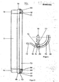
- Fig. 1 einen Querschnitt durch eine Leuchte,
- Fig. 2 eine Aufsicht auf die Leuchte mit teilweise aufgeschnittenen Hohlkörpern,
- Fig. 3 eine Seitenansicht der Leuchte,
- Fig. 4 eine Teilschnittansicht durch den Rand eines Leuchtengehäuses (Einzelheit der Fig. 5),
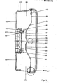
- Fig. 5 einen Querschnitt durch ein weiteres Ausführungsbeispiel eines Leuchtengehäuses und
- Fig. 6 eine Schnittansicht entsprechend der Figur 1, ohne Abdeckwanne zur Darstellung der Montage.
- Es sei bezug genommen auf die Figur 1. Die in der Figur 1 dargestellte Leuchte, die insgesamt die Bezugsziffer 10 besitzt, umfaßt zwei Hohlkörper 11 und 12, die in Abstand zueinander angeordnet und mittels seitlicher Abdeckhalteteile 13, 14 (siehe Figur 2) miteinander fest verbunden sind. Die beiden Hohlkörper 11 und 12 sind Metallhohlkörper und als extrudierte Hohlprofile ausgebildet. Der Hohlkörper 11 besitzt eine vordere Wand 15, auch Frontwand 15 genannt, eine Seitenwand 16, eine Rückwand 17 und eine Innenwand (bezogen auf die Leuchte 10) 18. Die Seitenwand 16, die eine der Seitenwände der gesamten Leuchte 10 bildet, besitzt eine Ausformung 19, die einen Fortsatz 20 aufweist, der angenähert senkrecht zur Frontwand 15 ausgerichtet ist. Die Ausformung 19 bildet zusammen mit der Frontwand 15 einen Rücksprung 21, wodurch eine längsverlaufende Nut 22 gebildet ist. An der Eckkante zwischen der Frontwand 15 und der Innenwand.18 ist eine Abschrägung 23 vorgesehen; die Frontwand 15 besitzt an der Übergangsstelle zu der Abschrägung 23 eine Nase 24, wodurch eine längsverlaufende Kerbnut 25 gebildet ist.
- An der Innenfläche 18 ist ein Vorsprung 26 vorgesehen, der eine nach vorn, also zur Vorderseite der Leuchte offene Längsnut 27 aufweist, in der eine Schraube 28 von vorne einschraubbar ist.
- An der Innenfläche der Seitenwand 16 und der gegenüberliegenden Innenfläche der Innenwand 18 sind Leisten 29 vorgesehen, die Führungsnuten 30 bilden, in die Leiterplatten 31 einschiebbar sind, die der Halterung von elektronischen oder elektrischen Bauteilen 32 bzw. 33 dienen. Im Inneren des Hoh1körpers 11 befindet sich weiterhin bei der in der Figur 1 dargestellten Leuchte ein Vorschaltgerät 34.
- Der Hohlkörper 12 ist in identischer Weise aufgebaut wie der Hohlkörper 11 und spiegelbildlich zum Hohlkörper 11 angeordnet. Im Inneren des Hohlkörpers 12 sind in die den Nuten 30 entsprechenden Nuten Tragplatten oder Leiterplatten 35 eingeschoben, auf denen Anschlüsse 36 für Batterien 37 befestigt sind. In die Kerbnuten 25 ist ein Reflektor 38 eingesetzt und darin verspannt, da der Abstand der sich gegenüberliegenden Kerbnuten 25 der beiden Hohlkörper 11 und 12 kleiner ist als der Abstand der Endkanten des Reflektors 38 im entspannten Zustand. Von dem Vorsprung 26 auf dessen der Längsnut 27 entgegengesetzten, d.h. hinteren Seite an den sich gegenüberliegenden Hohlkörpern 12 jeweils ein Absatz 39 bzw. 40 gebildet, wodurch ein Raum 41 begrenzt ist, der zur Aufnahme eines U-förmigen Montageteils 42 dient.
- Aus der Figur 2 ist ersichtlich, daß beidseitig zu den Hohlkörpern senkrecht dazu je eine Leiterplatte 47 und 48 angebracht ist, die Buchsenteile 49 und 50 tragen, mit denen Steckerstifte 51 und 52 an den Leiterplatten 31 und 35 ankuppelbar sind. Diese auch als Verbindungsleiterplatten bezeichneten Leiterplatten 47 und 48 tragen die Anschlußsockel 53 für die Leuchtstofflampe 46. Auf der Montageplatte 42 bzw. auf dem U-förmigen Montageteil 42 sind weiterhin auch Anschlußklemmenbausteine 54 befestigt, an denen Anschlußleiter 55 (Anschlußkabel 55).angeschlossen sind, die durch Öffnungen 56 in dem Montageteil 42 nach außen herausgeführt werden. Die elektrische Verbindung von dem Anschlußklemmenbaustein 54 zu den Leiterplatten 31 und 35 erfolgt steckbar über die Leiterplatte 44, einem Buchsenteil 43 und der Leiterplatte 47. Die Schrauben zur Verbindung der Verbindungsleiterplatten 47 und 48 mit den Seitenteilen 13 und 14 sind in Figur 6 mit der Bezugsziffer 57 bezeichnet.
- Die Verbindung der Seitenteile 13 und 14 mit den beiden Hohlprofilkörpern erfolgt mittels an den Seitenteilen 13 und 14 (nur am Seitenteil 14 sichtbar) angeformter Laschen 58 und 59, deren Enden gabelförmig mit Schlitzlöehern 60 ausgebildet sind. Mittels der Schrauben 28 werden die Laschen an den Vorsprüngen 26 befestigt, wobei die Schrauben 28 in die Nuten 22 eingeschraubt sind. Das Montageteil 42 ist dabei ein U-förmiger Bügel, der an einer Mauerwand 61 (Figur 6) mittels Dübelschrauben 62 befestigt ist. Daß dabei der U-förmige Bügel Durchzüge 63 aufweist, die den Schraubenköpfen angepaßt sind, ist selbstverständlich.
- Die Figur 3 zeigt eine praktisch vollständig montierte Leuchte 10 (ohne Wanne) von der Seite. Man erkennt die Außenfläche eines der beiden Hohlprofile, nämlich die des Hohlprofiles 11 und beidseitig dazu die an die äußere Kontur angepaßten Abdeckhalteteile 13 und 14. Diese Abdeckhalteteile weisen - der Kontur der Außenfläche 11 angepaßt - ebenfalls Vorsprünge 64 und 65 aufweisen. Sie besitzen ferner Noppen 66 und an ihrem einen Ende eine Vertiefung 67. Die Abdeckkappe 68 zur Abdeckung dieses Bereiches, die praktisch an die Abdeckhalteteile 13 und 14 anschließt, besitzt jeweils Öffnungen 69 in Form eines Sackloches und am anderen Ende eine Leiste 70. Im montierten Zustand greifen die Noppen 66 an dem Seitenteil-14 in die Öffnungen 69 und die Leiste 70 greift in die Längsvertiefung 67 ein, wodurch die Abdeckkappe 68 am Abdeckhalteteil 14 befestigt ist. Die Abdeckkappe 68 kann, wie in der Figur 3 oben dargestellt, darüberhinaus auch Durchbrechungen 71 aufweisen, durch die eine Leuchtdiode 72 nach außen hindurchgreift, an der die Betriebsart erkenntlich ist. Es besteht natürlich auch die Möglichkeit, daß dort anstatt einer Leuchtdiode auch ein Betätigungselement vorgesehen ist.
- Nach der Montage der beiden Hohlkörper 11 und 12 mittels der Abdeckhalteteile 13 und 14 ist eine durchsichtige Leuchtenwanne 73 anzubringen. Wie dies geschieht ist aus Figur 4 ersichtlich. Man erkennt die Ausformung 19 des Hohlkörpers 12 sowie den Fortsatz 20 und die dadurch gebildete Nut 22. Im Fortsatz 20 und zwar auf dessen Innenseite ist eine kreisbogenartige Vertiefung 74 ein gelegt, ist die eine entsprechende Leiste 74a an der Außenseite der Leuchtenwanne verrastbar ist. Die Leuchtenwanne 73 selbst ist dann mit einer Kappe 68 abgedeckt.
- An der Innenfläche der Abdeck- bzw. Leuchtenwanne 73 sind Konturierungen 77 (Figur 1) angeformt, die zur besseren Streuung des Lichtes dienen.
- Die Figur 5 zeigt eine weitere Ausgestaltung der Erfindung, allerdings nur schematisch und mit einigen weggelassenen Teilen. Die Hohlköprer besitzen hierbei die Bezugsziffern 80 und 81 mit ihren Seitenwänden 82, den Frontwänden 83, den inneren oder den Innenwänden 84 und den Rückwänden 85. Die Frontwand 83 geht in die Innenwand 84 über eine Abschrägung 86 über und die Abschrägung 86 setzt sich in eine Fahne 87 fort, die zusammen mit der Fahne 88 des anderen Hohlkörpers 81 den Reflektor für die Leuchtstofflampe 46 bilden. Unterschiedlich zu dem Hohlkörperprofil gemäß Figur 1 ist die geänderte Ausführung des Vorsprunges 89. Der Vorsprung 89 besitzt die Längsnut 90 auf der Gehäuserückseite und über an den Seitenteile angeformte, an einer gegenüber der Ausführung nach Figuren 1 bis 3 anderen Stelle angebrachte Laschen 91 werden die Seitenteile mittels Schrauben 92 mit den Hohlkörpern 80 und 81 fest verbunden. Die Schrauben sind dabei von hinten zugänglich.
- Zusätzlich sind noch auf der Innenseite der Frontwand 83 Rippen 93 vorgesehen, die zur Führung weiterer Bauelemente oder ggf. auch zur verbesserten Wärmeabfuhr dienen.
- Die Reflektorform besitzt in der Ausführung gemäß Figur 1 eine dachartige Form mit zwei ersten Reflektorflächen 94 und 95, die einen stumpfen Winkel zwischen sich einschließen. Im mittleren Bereich zwischen den beiden ersten Reflektorflächen 94 und 95 sind zwei ebenfalls einen stumpfen Winkel zwischen sich einschließende zweite Reflektorflächen 96 und 97 vorgesehen, deren Spitze zur Lampe 46 zu- bzw. deren Winkelöffnung zur Rückseite der Leuchte hinweist. Demgemäß wird mittels der etwa zickzackförmig gebogenen Reflektorflächen 94, 95, 96 und 97 eine bestimmte breitflächige Reflexion und breitflächige Lichtstreuung bewirkt, die ggf. noch durch die Konturen bzw. Profilierung 77 der Leuchtenwanne 73 auf deren Innenfläche unterstützt werden kann. Der Reflektor gemäß Figur 5 wird zunächst gebildet durch die beiden Abschrägungen 86 der beiden Hohlkörper 80 und 81. Die durch die Abschrägungen 86 gebildete Reflektorfläche setzt sich dabei nach innen über die Innenwandung 84 um einen bestimmten Betrag hinaus fort, geht dann über in einen parallel zur vorderen Fläche der Abdeckwanne 73 verlaufenden Bereich 98, an den sich ein zur Lampe 46 hin abgeknickter Reflexionsbereich 99 jeweils anschließt, wodurch im Prinzip eine ähnliche Kontur gebildet ist wie bei dem Reflektor 38 der Figur 1.
- Anhand der Figur 6 soll die Montage der Leuchte näher dargestellt werden. Der Reflektor 38 besitzt in der Mitte eine Öffnung 100, durch die ein Schraubendreher 101 hindurchsteckbar ist. Auf den Vorsprüngen 26 ist eine Traverse 102 aufgelegt, durch die hindurch eine Schraube 103 greift. Diese Traverse 102 kann durch einfaches Verdrehen der Schraube 103, die in den U-förmigen Montagebügel 42 eingeschraubt ist, verdreht werden, wobei ein Anschlagstift 104 vorgesehen ist, damit der Montagebügel nicht über eine bestimmte mittlere Lage (Montagelage) hinaus verdreht werden kann. Durch Aufschrauben der Schraube wird mittels einer Feder 105 die Traverse 102 von den beiden Vorsprüngen 26 abgehoben und wegen der durch die Feder 105, die die Traverse 102 gegen den Schraubenkopf drückt, bewirkten Selbsthemmung kann die Traverse 102 verdreht werden. Beim Einschrauben bewegt sich die Traverse 102 gegen den Anschlagstift 104 und kann sich nicht mehr weiter verdrehen. Auf diese Weise kann die Schraube 103 in das Montageblech bzw. den Montageteil 42 eingeschraubt werden. Bei der Ausführung der Hohlkörper 80 und 81 gemäß Figur 5 ist eine ähnliche Öffnung zwischen den beiden Fahnen 87 und 88 vorgesehen.
- Der Raum zwischen den beiden Hohlkörpern 11 und 12 bzw. 80 und 81 kann dann als Raum zur Verlegung von elektrischen Leitungen und dergleichen verwendet werden,-insbesondere von elektrischen Leitungen, die der Stromzuführung dienen, siehe Bezugsziffer 55. Zu diesem Zwecke ist zusätzlich zum Montageteil 42 eine durchgehende Montageplatte vorgesehen, wobei wandseitig ein Kabelkanal 107 gebildet ist. Die Abdeckhalteteile 13 und 14 besitzen ausbrechbare Vorkerbungen 108, durch die die Kabel 55 aus dem Gehäuse herausgeführt werden können, sofern eine Aufputz-Montage erforderlich ist. Selbstverständlich kann die genannte Leuchte auch als sogenannte normale Leuchte verwendet werden; dann wäre der Batteriesatz 37 nicht erforderlich.
Claims (14)
Priority Applications (1)
| Application Number | Priority Date | Filing Date | Title |
|---|---|---|---|
| AT86105058T ATE59893T1 (de) | 1985-04-16 | 1986-04-12 | Leuchte, insbesondere notleuchte. |
Applications Claiming Priority (2)
| Application Number | Priority Date | Filing Date | Title |
|---|---|---|---|
| DE3513498 | 1985-04-16 | ||
| DE3513498 | 1985-04-16 |
Publications (3)
| Publication Number | Publication Date |
|---|---|
| EP0199230A2 true EP0199230A2 (de) | 1986-10-29 |
| EP0199230A3 EP0199230A3 (en) | 1988-09-07 |
| EP0199230B1 EP0199230B1 (de) | 1991-01-09 |
Family
ID=6268088
Family Applications (1)
| Application Number | Title | Priority Date | Filing Date |
|---|---|---|---|
| EP86105058A Expired - Lifetime EP0199230B1 (de) | 1985-04-16 | 1986-04-12 | Leuchte, insbesondere Notleuchte |
Country Status (3)
| Country | Link |
|---|---|
| EP (1) | EP0199230B1 (de) |
| AT (1) | ATE59893T1 (de) |
| DE (1) | DE3676735D1 (de) |
Cited By (5)
| Publication number | Priority date | Publication date | Assignee | Title |
|---|---|---|---|---|
| FR2674316A1 (fr) * | 1991-03-22 | 1992-09-25 | Pagnol Frederic | Balise alimentee par cellules photovoltauiques. |
| EP0677698A1 (de) * | 1994-04-16 | 1995-10-18 | ITT Reiss International GmbH | Leuchtenverschluss |
| FR2786255A1 (fr) * | 1998-11-25 | 2000-05-26 | Legrand Sa | Luminaire a platine interne susceptible d'etre disposee a l'un ou l'autre de deux niveaux differents |
| EP0950849A3 (de) * | 1998-04-16 | 2001-04-18 | NORKA Norddeutsche Kunststoff- und Elektro-Gesellschaft Stäcker & Co. mbH | Leuchte für langgestreckte Leuchtstofflampen, insbesondere in staub- und wasserdichter Ausführung |
| FR2810724A1 (fr) * | 2000-06-23 | 2001-12-28 | H E Williams Inc | Appareil d'eclairage a fluorescence |
Family Cites Families (9)
| Publication number | Priority date | Publication date | Assignee | Title |
|---|---|---|---|---|
| US2399501A (en) * | 1944-11-06 | 1946-04-30 | Gen Electric | Tubular lamp fixture |
| DE942883C (de) * | 1952-04-29 | 1956-05-09 | Hoppemann & Mulsow | Luft- und wasserdichte Leuchte fuer die Verwendung von Leuchtstofflampen oder anderen roehrenfoermigen Lampen unterschiedlicher Laenge |
| DE1054173B (de) * | 1956-06-12 | 1959-04-02 | Licentia Gmbh | Leuchte fuer Leuchtstofflampen |
| CH485168A (de) * | 1968-01-10 | 1970-01-31 | Mekapro Ag | Montagearmatur für Leuchtstoffröhren |
| US3514590A (en) * | 1968-04-16 | 1970-05-26 | Calculations Inc | Fluorescent luminaire |
| US4006354A (en) * | 1975-07-09 | 1977-02-01 | Gte Sylvania Incorporated | Low-profile lighting fixture |
| IT1071265B (it) * | 1976-05-04 | 1985-04-02 | Wabco Westinghouse Spa | Sopporto con convertitore incorpora to per lampade fluorescenti particolarmente per l illuminazione di veicoli |
| DE2643200A1 (de) * | 1976-09-23 | 1978-03-30 | Sill Franz Gmbh | Offene leuchte |
| FR2389069A1 (fr) * | 1977-04-25 | 1978-11-24 | Eta | Bloc de support et d'alimentation pour lampes fluorescentes |
-
1986
- 1986-04-12 EP EP86105058A patent/EP0199230B1/de not_active Expired - Lifetime
- 1986-04-12 AT AT86105058T patent/ATE59893T1/de not_active IP Right Cessation
- 1986-04-12 DE DE8686105058T patent/DE3676735D1/de not_active Expired - Fee Related
Cited By (8)
| Publication number | Priority date | Publication date | Assignee | Title |
|---|---|---|---|---|
| FR2674316A1 (fr) * | 1991-03-22 | 1992-09-25 | Pagnol Frederic | Balise alimentee par cellules photovoltauiques. |
| EP0677698A1 (de) * | 1994-04-16 | 1995-10-18 | ITT Reiss International GmbH | Leuchtenverschluss |
| EP0950849A3 (de) * | 1998-04-16 | 2001-04-18 | NORKA Norddeutsche Kunststoff- und Elektro-Gesellschaft Stäcker & Co. mbH | Leuchte für langgestreckte Leuchtstofflampen, insbesondere in staub- und wasserdichter Ausführung |
| FR2786255A1 (fr) * | 1998-11-25 | 2000-05-26 | Legrand Sa | Luminaire a platine interne susceptible d'etre disposee a l'un ou l'autre de deux niveaux differents |
| EP1004816A1 (de) * | 1998-11-25 | 2000-05-31 | Legrand | Leuchte mit einer inneren Trägerplatte, die auf einer der zwei verschiedenen Höhen aufgestellt werden kann |
| FR2810724A1 (fr) * | 2000-06-23 | 2001-12-28 | H E Williams Inc | Appareil d'eclairage a fluorescence |
| GB2363839A (en) * | 2000-06-23 | 2002-01-09 | H E Williams Inc | Fluorescent light fixture with offset ballast-mounting |
| GB2363839B (en) * | 2000-06-23 | 2004-08-25 | H E Williams Inc | A fluorescent lighting fixture with offset ballast housing |
Also Published As
| Publication number | Publication date |
|---|---|
| EP0199230A3 (en) | 1988-09-07 |
| ATE59893T1 (de) | 1991-01-15 |
| DE3676735D1 (de) | 1991-02-14 |
| EP0199230B1 (de) | 1991-01-09 |
Similar Documents
| Publication | Publication Date | Title |
|---|---|---|
| EP2815171B1 (de) | Lichtbandsystem | |
| DE102008052869B4 (de) | Leuchte mit LED-Tragschiene | |
| DE102014112657B4 (de) | Leuchte für ein Lichtbandsystem | |
| EP1546604B1 (de) | Beleuchtungsvorrichtung | |
| DE202008006326U1 (de) | LED-Beleuchtungskörper | |
| DE202007016530U1 (de) | Elektrische Leuchte | |
| AT16083U1 (de) | Feuchtraumleuchte in Wannenbauform | |
| EP0138746B1 (de) | Leuchte mit begleitender linearer Lichtquelle | |
| EP1649209B1 (de) | Leuchte für beleuchtungszwecke | |
| DE19607208A1 (de) | Leuchtstofflampe mit auswechselbarem Leuchtteil | |
| AT515246A2 (de) | Profilleuchtensystem und Montageverfahren dafür | |
| EP2123976B1 (de) | Einbauleuchte | |
| WO2009121559A1 (de) | Leuchte | |
| DE102009042615B4 (de) | Anschlusselement zur elektrischen Anbindung einer LED | |
| DE19953132A1 (de) | Fahrzeugleuchte | |
| EP1670107A1 (de) | Schaltschrank, Geräteschrank oder dergleichen Schrank mit einer elektrischen Leuchte | |
| EP0199230B1 (de) | Leuchte, insbesondere Notleuchte | |
| EP3366991A1 (de) | Geräteträger für leuchte | |
| DE8511045U1 (de) | Leuchte, insbesondere Notleuchte | |
| DE3612319A1 (de) | Leuchte, insbesondere notleuchte | |
| EP2175188B1 (de) | Leuchte | |
| EP2963341B1 (de) | Leuchtenanordnung für leuchten beispielsweise mit leds | |
| DE19721340A1 (de) | Leuchte | |
| EP2629004B1 (de) | Einbauleuchte für den Außenbereich, insbesondere zur Montage in einem Fensterrahmenprofil | |
| EP0132687B1 (de) | Leuchte für eine Kompakt-Leuchtstofflampe |
Legal Events
| Date | Code | Title | Description |
|---|---|---|---|
| PUAI | Public reference made under article 153(3) epc to a published international application that has entered the european phase |
Free format text: ORIGINAL CODE: 0009012 |
|
| AK | Designated contracting states |
Kind code of ref document: A2 Designated state(s): AT BE CH DE FR GB IT LI NL |
|
| PUAL | Search report despatched |
Free format text: ORIGINAL CODE: 0009013 |
|
| AK | Designated contracting states |
Kind code of ref document: A3 Designated state(s): AT BE CH DE FR GB IT LI NL |
|
| RAP1 | Party data changed (applicant data changed or rights of an application transferred) |
Owner name: ABB CEAG LICHT- UND STROMVERSORGUNGSTECHNIK GMBH |
|
| 17P | Request for examination filed |
Effective date: 19890213 |
|
| 17Q | First examination report despatched |
Effective date: 19900607 |
|
| GRAA | (expected) grant |
Free format text: ORIGINAL CODE: 0009210 |
|
| AK | Designated contracting states |
Kind code of ref document: B1 Designated state(s): AT BE CH DE FR GB IT LI NL |
|
| REF | Corresponds to: |
Ref document number: 59893 Country of ref document: AT Date of ref document: 19910115 Kind code of ref document: T |
|
| ITF | It: translation for a ep patent filed | ||
| REF | Corresponds to: |
Ref document number: 3676735 Country of ref document: DE Date of ref document: 19910214 |
|
| ET | Fr: translation filed | ||
| GBT | Gb: translation of ep patent filed (gb section 77(6)(a)/1977) | ||
| PLBE | No opposition filed within time limit |
Free format text: ORIGINAL CODE: 0009261 |
|
| STAA | Information on the status of an ep patent application or granted ep patent |
Free format text: STATUS: NO OPPOSITION FILED WITHIN TIME LIMIT |
|
| 26N | No opposition filed | ||
| PGFP | Annual fee paid to national office [announced via postgrant information from national office to epo] |
Ref country code: GB Payment date: 19950220 Year of fee payment: 10 |
|
| PGFP | Annual fee paid to national office [announced via postgrant information from national office to epo] |
Ref country code: CH Payment date: 19950223 Year of fee payment: 10 |
|
| PGFP | Annual fee paid to national office [announced via postgrant information from national office to epo] |
Ref country code: AT Payment date: 19950224 Year of fee payment: 10 |
|
| PGFP | Annual fee paid to national office [announced via postgrant information from national office to epo] |
Ref country code: FR Payment date: 19950310 Year of fee payment: 10 |
|
| PGFP | Annual fee paid to national office [announced via postgrant information from national office to epo] |
Ref country code: BE Payment date: 19950322 Year of fee payment: 10 |
|
| PGFP | Annual fee paid to national office [announced via postgrant information from national office to epo] |
Ref country code: DE Payment date: 19950425 Year of fee payment: 10 |
|
| PGFP | Annual fee paid to national office [announced via postgrant information from national office to epo] |
Ref country code: NL Payment date: 19950430 Year of fee payment: 10 |
|
| PG25 | Lapsed in a contracting state [announced via postgrant information from national office to epo] |
Ref country code: GB Effective date: 19960412 Ref country code: AT Effective date: 19960412 |
|
| PG25 | Lapsed in a contracting state [announced via postgrant information from national office to epo] |
Ref country code: LI Effective date: 19960430 Ref country code: CH Effective date: 19960430 Ref country code: BE Effective date: 19960430 |
|
| BERE | Be: lapsed |
Owner name: ABB CEAG LICHT- UND STROMVERSORGUNGSTECHNIK G.M.B Effective date: 19960430 |
|
| PG25 | Lapsed in a contracting state [announced via postgrant information from national office to epo] |
Ref country code: NL Effective date: 19961101 |
|
| GBPC | Gb: european patent ceased through non-payment of renewal fee |
Effective date: 19960412 |
|
| REG | Reference to a national code |
Ref country code: CH Ref legal event code: PL |
|
| PG25 | Lapsed in a contracting state [announced via postgrant information from national office to epo] |
Ref country code: FR Effective date: 19961227 |
|
| PG25 | Lapsed in a contracting state [announced via postgrant information from national office to epo] |
Ref country code: DE Effective date: 19970101 |
|
| NLV4 | Nl: lapsed or anulled due to non-payment of the annual fee |
Effective date: 19961101 |
|
| REG | Reference to a national code |
Ref country code: FR Ref legal event code: ST |
|
| PG25 | Lapsed in a contracting state [announced via postgrant information from national office to epo] |
Ref country code: IT Free format text: LAPSE BECAUSE OF NON-PAYMENT OF DUE FEES;WARNING: LAPSES OF ITALIAN PATENTS WITH EFFECTIVE DATE BEFORE 2007 MAY HAVE OCCURRED AT ANY TIME BEFORE 2007. THE CORRECT EFFECTIVE DATE MAY BE DIFFERENT FROM THE ONE RECORDED. Effective date: 20050412 |