EP0199312A2 - Procédé et dispositif de détermination du frottement superficiel ou de la viscosité d'un liquide sur un modèle ou autre objet en contact avec l'écoulement - Google Patents
Procédé et dispositif de détermination du frottement superficiel ou de la viscosité d'un liquide sur un modèle ou autre objet en contact avec l'écoulement Download PDFInfo
- Publication number
- EP0199312A2 EP0199312A2 EP86105414A EP86105414A EP0199312A2 EP 0199312 A2 EP0199312 A2 EP 0199312A2 EP 86105414 A EP86105414 A EP 86105414A EP 86105414 A EP86105414 A EP 86105414A EP 0199312 A2 EP0199312 A2 EP 0199312A2
- Authority
- EP
- European Patent Office
- Prior art keywords
- sensor
- light beam
- liquid
- light
- layer
- Prior art date
- Legal status (The legal status is an assumption and is not a legal conclusion. Google has not performed a legal analysis and makes no representation as to the accuracy of the status listed.)
- Granted
Links
Images


Classifications
-
- G—PHYSICS
- G01—MEASURING; TESTING
- G01N—INVESTIGATING OR ANALYSING MATERIALS BY DETERMINING THEIR CHEMICAL OR PHYSICAL PROPERTIES
- G01N13/00—Investigating surface or boundary effects, e.g. wetting power; Investigating diffusion effects; Analysing materials by determining surface, boundary, or diffusion effects
-
- G—PHYSICS
- G01—MEASURING; TESTING
- G01M—TESTING STATIC OR DYNAMIC BALANCE OF MACHINES OR STRUCTURES; TESTING OF STRUCTURES OR APPARATUS, NOT OTHERWISE PROVIDED FOR
- G01M10/00—Hydrodynamic testing; Arrangements in or on ship-testing tanks or water tunnels
-
- G—PHYSICS
- G01—MEASURING; TESTING
- G01N—INVESTIGATING OR ANALYSING MATERIALS BY DETERMINING THEIR CHEMICAL OR PHYSICAL PROPERTIES
- G01N11/00—Investigating flow properties of materials, e.g. viscosity, plasticity; Analysing materials by determining flow properties
Definitions
- the invention relates to a method for determining the wall shear stress or the viscosity of liquids on models and other flow-around bodies, in which a viscous transparent liquid is applied in a layer to the surface of the body at the measuring point and the thickness and / or change in the surface inclination of the layer is detected with a light beam.
- the invention also shows a device for carrying out this method with a light source, a layer of a viscous transparent liquid and a photodiode for detecting the reflected light beam.
- a body with a flow around it can be a wind tunnel model, but also an original device on the ground or in the air, for example a car or an aircraft.
- the data to be determined experimentally are often used to check universal laws and theoretical models, so that it is necessary to carry out the measurement of the wall shear stress with appropriate accuracy and without affecting the flow.
- a method and a device of the type described at the outset are described by TANNER & BLOWS, "A study of the motion of oil films on surfaces in airflow, with application to the measurement of skin friction ", Journal of Physics E: Scientific Instruments 1976, Vol. 9, pp. 194-202. It is thus possible to measure the absolute value of the wall shear stress optically without contact.
- An oil film is applied from the outside to the surface of the model. Also from the outside, a light beam generated by a laser is directed onto the oil film. One part of the light beam reflects on the surface of the oil film, another part on the surface of the model Light is collected by a collecting lens. A photodiode is used to detect the changing brightness, which results from interference.
- a point-like measurement at the individual measuring point is therefore possible.
- the fact that a thin oil film due to the Wall shear stress T at constant flow conditions with time t on the travel element d in the direction of flow undergoes a change in thickness y according to the formula is equal to the inverse wall shear stress ⁇ , which means the viscosity of the oil film used.
- the method boils down to determining the two variables t (in the range of seconds) and y (in the range of approx. 100 ⁇ m) with known ⁇ and d.
- the use of this known method has numerous disadvantages. Sufficiently large windows for supplying the light beam and for deriving the reflected light beam, e.g. B.
- the wind tunnel in which the model is examined can be provided in the wind tunnel in which the model is examined.
- the method is practically not applicable in wind tunnels without windows. Even with dynamic examinations on moving The method cannot be carried out on objects, in particular aircraft, since both the light source and the evaluation device must be carried along. Furthermore, extensive adjustment work is necessary when using this method. To prepare each measurement and each time the model changes its angle, the wind tunnel operation must be interrupted so that the measurement takes a correspondingly long time and causes great costs. If the surface of the model is very curved where it is to be measured, this makes the measurement difficult; in special cases the measurement becomes impossible because the reflected light can no longer be recorded.
- Both reflected rays interfere with each other.
- a change in the intensity of light-dark-light is determined in the photodetector, which changes over time as the thickness decreases.
- the viscosity can be determined by counting.
- the method described first can be refined and then achieves a fairly high accuracy; however, larger quantities of the liquid to be examined are required. Viscosity determinations in the molecular range (medicine) are not possible. In contrast, this method is advantageous insofar as non-transparent liquids can also be examined.
- the beam reflected at the interface between the liquid and the solid body is impaired by the thickness of the liquid layer, so that different interference conditions result.
- the accuracy of this method is limited in that the point of impact of the jet sent onto the liquid depends on the layer thickness of the liquid and is therefore not constant. There are also adjustment difficulties.
- the invention has for its object to provide a method and a device with which it is possible to measure the wall shear stress absolutely or relatively in size, direction and distribution without significant disturbance of the flow or the viscosity of liquids.
- the measurement should also be without Interruption of the flow should be repeatable:
- the measurement should also be carried out during dynamic tests, e.g. B. on flying bodies.
- this is achieved in that the light beam from the interior of the body around which flow is directed in the direction of the surface of the body and into the layer of the viscous liquid and that the reflected light beam is collected in the interior of the body around which flow.
- the invention thus turns away from the prior art and uses the light beam from the other side - that is, from the inside - to determine the wall shear stress absolutely.
- This has the great advantage that the measurement is independent of the external conditions, e.g. B. the formation of a wind tunnel, and that the measuring device can be carried in a simple manner with the flowed body or in the flowed body when z. B. a measurement is to be carried out on a moving car or an aircraft. The flow around the body is not affected by the measuring device.
- a major advantage of the method according to the invention is that each measurement can be repeated without interrupting the flow conditions. It is very easy to re-form the layer of viscous liquid to repeat the measurement or, if necessary, to use a liquid of a different viscosity.
- the viscous liquid in addition to the light beam, is also directed from the inside of the body around which it is flowing to the surface of the body. This means that the layer of viscous liquid can be re-formed at any time without affecting the flow. It is also possible to use several light beams in connection with a line for the viscous liquid in order to determine the distribution of the wall shear stress. The Wall shear stress at every measuring point can be read off immediately.
- the angle of the illuminating beam advantageously always remains constant, regardless of the layer thickness and the layer inclination.
- the device for carrying out the method works with a light source, a layer of a viscous transparent liquid and a photodiode for detecting the reflected light beam.
- the device for determining the thickness and / or surface inclination has a planar sensor that can be installed flush with the surface of the body around which the flow is flowing, and that a channel for applying the liquid that ends in the sensor surface and at least one light line that also ends in the sensor surface are provided for supplying the light beam and for deriving the reflected light beam.
- a Michelson interferometer, a photodiode and a downstream evaluation electronics can be provided for the detection.
- the new area sensors can be used again and again, i. H.
- the areal sensor replaces part of the surface of the model or the body around which it flows and thus itself forms part of the surface of the body around which it flows at the measuring point.
- the entire measuring device or its essential parts are accommodated in the interior of the flow-around body, so that the flow around the body cannot be impaired thereby.
- the device When determining the viscosity of liquids, the device is rotated by 90 ° so that the measuring point or the surface of the sensor is arranged vertically. In this new arrangement and through the use of the beam path from the inside, the angle of the illuminating beam always remains constant regardless of the layer thickness and the layer inclination.
- Optical fiber cables can be provided as the light guide and a laser as the light source. This makes it possible to use the sensor even under difficult installation conditions.
- the sensor can also have a plurality of light lines ending in the sensor surface in order to determine the distribution of the wall shear stress in the surface.
- a plane is defined by the ends of at least three light pipes, so that their inclination can also advantageously be determined.
- Another measuring point can be used for checking. It is also possible to use other channels assigned to the individual measuring points for liquids with different viscosities.
- a resolution of a few mm 2 can also be achieved in the local absolute determination of the wall shear stress.
- the determination of the wall shear stress is also possible with the invention in the case of complicated flows, in particular 3-D flows, flows with pressure or shear stress gradients.
- the senor can consist of light-conducting material and extend normally to the surface around which the body flows.
- the sensor ends there in a transparent surface in which a deflection prism for the light beam to be supplied and a position-free diode for the reflected light beam are provided without reflection.
- the position diode can be a four-quadrant diode, a ZD line matrix or the like. This simplifies it the device with which only the change in surface inclination can be determined.
- the sensor made of light-conducting material can have a block shape and have a beam-dividing cut. Corrective optics for expanding and / or adjusting the divided beam are provided on the sensor.
- the sensor is assigned a second sensor made of light-conducting material, which is arranged at a right angle to it, so that in the area of this second sensor the divided beam and the reflected beam are brought into interference with one another.
- the sensor with its surface over which the liquid flows is arranged vertically.
- the sensor (1) shown in Figure 1 consists of a flat element of a certain extent, which is flush with the surface (2) Surface (3) of the flow-around body (4) can be installed.
- the flow around the body (4) takes place on the outside thereof according to the arrow (5).
- a channel (6) ends in the sensor (1) and is connected to a tube (7).
- the tube (7) and the channel (6) serve to introduce a transparent viscous liquid as a layer (8) onto the surface (2) and thus into the surface (3) of the body (4) around which it flows.
- the layer (8) is drawn here with the same thickness over the areal extent of the sensor (1) and will experience a local change in thickness as a result of the flow around it (arrow).
- a plurality of light lines (9) terminate in the sensor (1) or its surface (2), which are designed in particular as optical fiber cables. These light lines (9) are connected to an arm (10) of a Michelson interferometer (11).
- the ends (12) of the light pipes (9) in the surface (2) can be arranged in the manner of a square, as shown in FIG. 2, the end (13) of the channel (6) or the tube (7) in the center may be appropriate.
- a laser ° (14) is provided to generate the light beam, followed by a beam splitter (15).
- the light is fed to the Michelson interferometer (11) with a light guide (16).
- a photodiode (17) and evaluation electronics (18) are provided for evaluating the reflected light beam.
- a certain amount of the liquid is discharged through the tube (7) and the channel (6) on the surface (2) of the sensor (1) before or during the occurrence of the flow conditions according to arrow (5), so that it spreads out on the surface.
- the light generated by the laser (14) arrives Via the beam splitter (15), the light line (16) to the Michelson interferometer (11) and from its arm (10) via the light line (9) into the end (12), i.e. also into the surface and thus into the layer (8) the viscous liquid.
- changes in brightness of the reflected light occur on the photodiode (17) and are registered due to interference in the photodiode (17) and evaluated in the downstream evaluation electronics (18).
- the light enters from the arms (10) of the interferometer (11) in the free ends (12) of the light pipes (9) into the layer (8) of the liquid and is partially reflected at the boundary between the liquid and the air flowing around it.
- changes in brightness are detected in the photodiode (17) when the light path changes due to the changing thickness of the layer (8) of the liquid under the flow conditions.
- the change in thickness of the layer (8) can be determined simultaneously at four points on the sensor, namely at the four ends (12) of the light pipes (9). This is done with the aid of the evaluation electronics (18) as a function of time, which also continuously calculates the wall shear stress and its direction from the different changes in thickness at the four points.
- the device shown in Figure 3 uses a sensor (1) made of a translucent body, in particular glass, which can be designed as a round rod.
- This sensor (1) is again used with its surface (2) flush with the surface (3) of the body (4) around which it flows. It also extends normal to the surface (3) and ends in a surface (19), which can in particular be arranged parallel to the surface (2).
- the sensor (1) may have the length L here.
- the viscous liquid can be discharged onto the surface (2) via the channel (6), so that the layer (8) forms as a result of the flow conditions according to arrow (5), which here is wedge-shaped at an angle 2 due to the flow conditions trains and changes.
- a laser beam (20) is focused on a position diode (25) with focusing optics (21) and enters the sensor (1) through an entrance window (22) and a deflecting prism (23) at an angle ⁇ .
- the light beam passes through the surface (2) into the layer (8.) of the liquid and is partially reflected at the boundary of the liquid and the fluid flowing around the body (4) according to arrow (5), whereby it is directed onto the surface (19) is thrown back and reaches the position diode (25) at a point of impact (24).
- the point of impact (24) on the position diode (25) is predetermined by the angle ⁇ and the length L of the sensor and the layer thickness d.
- the layer of oil e.g. B. silicone oil
- the layer (8) adjusts itself at an angle of inclination ⁇ with respect to the surface (2) and thus the surface (3) of the body (4)
- the impact point (24) migrates the xy plane of the position diode (25).
- the position diode (25) is like this formed and arranged so that the impact point (24) can be determined in its xy plane, so that in addition to the angle of inclination #, the direction of inclination of the surface of the layer (8) can also be measured.
- the changes in the point of impact (24) are specified with öx and ⁇ y, then being because the temporal change in the angle of inclination ⁇ provides the amount and the ratio ⁇ x / ⁇ y in the xy plane provides the direction of the wall shear stress. Since the light beam emerges from its surface (2) above the deflection prism (23) at an angle ⁇ relative to the axis of the sensor (1), the angle cC must be taken into account accordingly in the evaluation. However, it is also possible to drill through the position diode (25) and to work without a deflection prism (23). The laser beam (20) then enters the sensor (1) centrally via the bore of the position diode (25) and can be detected on the position diode (25) with a corresponding deflection.
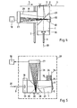
- FIG. 4 shows the essential parts of a further embodiment of the device.
- a laser beam (20) is fed via a light guide (9) to processing optics (26), which widens the light beam in the usual way and images it on a detector (27).
- the processed light beam passes through the sensor (1), which has a beam-splitting section (28) and thus has the function of a conventional beam splitter cube.
- the light beam is partially reflected at the interface between liquid and air of the layer (8) of the liquid and ultimately reaches the detector (27) as a reflected beam (29), which is formed from four quadrant photodiodes can.
- the deflection of the reflected beam (29) is detected both in the vertical and in the horizontal direction by means of evaluation electronics (18) connected downstream of the detector (27).
- a divided beam (30) is directed through the beam-splitting cut (28) to a correction lens (32) and expanded there, this beam also passing from the sensor (1) into the second sensor (31) and ultimately also onto the detector ( 27) arrives, but in an expanded form.
- the reflected beam (29) deflected to the detector (27) interferes with the divided beam (30), which can possibly be adjusted accordingly via the correction optics (32) .
- This arrangement thus functions like a Michelson interferometer, and with the aid of the detector (27) changes in intensity can be observed which result from changes in path length in the layer (8) of the viscous liquid.
- the liquid can be supplied via a line or a tube (7) in such a way that it ultimately reaches the surface of the flowed-around body as a layer (8) and thus to the measuring point. To the wall shear stress too two evaluation methods are possible.
- the deflection in the detector (27) is detected in two directions as a function of time.
- the number of fluctuation periods as a function of time provides information about the wall shear stress.
- the device according to FIG. 4 can of course also be used in an arrangement rotated through 90 ° for determining the viscosity of liquids.
- FIG. 5 shows a similarly structured arrangement for determining the viscosity of liquids.
- a laser beam (20) is fed to processing optics (26) via a light guide (9), which is designed here as focusing optics in order to image the reflected beam (29) on the detector (27).
- the beam processed in this way by the processing optics (26) passes through the sensor (1), which is designed as a transparent block and has a beam-dividing cut (28).
- the sensor (1) which is designed as a transparent block and has a beam-dividing cut (28).
- This also means that the beam introduced is divided here into a reflected beam (29) and a split beam (30).
- the processed beam is first partially reflected on the vertical surface (2) of the sensor (1) between the material of the transparent block and the liquid, and partly deflected at the beam-dividing cut (28).
- Both beams ultimately pass through the second sensor (31) and reach the detector (27), which is designed as a photodetector.
- Another part of the processed beam is reflected at the boundary layer between liquid and air and, as a reflected beam (29), also reaches the second sensor (31) and thus the detector (27) via the beam-dividing cut (28).
- the divided beam (30) can be equipped with correction optics (32) expanded and adjusted also reach the detector (27) so that interference occurs there.
- the partial beam reflected in itself at the interface between the sensor (1) and the air interferes with the deflected beam (30) at the detector (27).
- the result of this interference is either a large or a small light intensity - regardless of the time, i.e. constant -.
- a tear (37) forms on the surface due to gravity (2), which is arranged vertically, flows down. Due to the interaction of the various forces, a new interface between air and liquid is formed that is not parallel to the surface (2). The reflected and deflected beam (29) arises at this interface.
- the thickness d of the interface ' is at time t at a distance x from the outflow opening (35)' according to the formula reproduced, the viscosity of the liquid as well as the constant acceleration due to gravity g and the density e of the liquid.
- the reflected beam (29) is now essentially reflected at this new interface between liquid and air. Since the thickness d changes with time t, the interference conditions also change continuously. Now the light intensity changes as a function of time t, with a change in intensity light-dark-light one Thickness change from corresponds. Since the time t is in the denominator in the formula given above, the thickness changes are large for small times. As a result, the changes in intensity are also very rapid and can only be registered using electronic means, for example in the downstream evaluation electronics (18). For very large times t, the change between light-dark-light takes hours, ie there are changes in thickness in the molecular range.
- the gravitational force must be known exactly for the measurement.
- Surface (2) should be vertical so that gravitational acceleration g can act accordingly.
- the surface (2) is expediently aligned vertically using a spirit level (38).
- the entire device is housed in a thermostatted container (39).
Landscapes
- Physics & Mathematics (AREA)
- General Physics & Mathematics (AREA)
- Health & Medical Sciences (AREA)
- Life Sciences & Earth Sciences (AREA)
- Chemical & Material Sciences (AREA)
- Analytical Chemistry (AREA)
- Biochemistry (AREA)
- General Health & Medical Sciences (AREA)
- Immunology (AREA)
- Pathology (AREA)
- Fluid Mechanics (AREA)
- Length Measuring Devices By Optical Means (AREA)
Applications Claiming Priority (2)
| Application Number | Priority Date | Filing Date | Title |
|---|---|---|---|
| DE19853514801 DE3514801A1 (de) | 1985-04-24 | 1985-04-24 | Verfahren und vorrichtung zur bestimmung der wandschubspannung an modellen und anderen umstroemten koerpern |
| DE3514801 | 1985-04-24 |
Publications (3)
| Publication Number | Publication Date |
|---|---|
| EP0199312A2 true EP0199312A2 (fr) | 1986-10-29 |
| EP0199312A3 EP0199312A3 (en) | 1988-03-16 |
| EP0199312B1 EP0199312B1 (fr) | 1991-02-06 |
Family
ID=6269002
Family Applications (1)
| Application Number | Title | Priority Date | Filing Date |
|---|---|---|---|
| EP86105414A Expired - Lifetime EP0199312B1 (fr) | 1985-04-24 | 1986-04-18 | Procédé et dispositif de détermination du frottement superficiel ou de la viscosité d'un liquide sur un modèle ou autre objet en contact avec l'écoulement |
Country Status (2)
| Country | Link |
|---|---|
| EP (1) | EP0199312B1 (fr) |
| DE (2) | DE3514801A1 (fr) |
Cited By (1)
| Publication number | Priority date | Publication date | Assignee | Title |
|---|---|---|---|---|
| EP0391801A1 (fr) * | 1989-04-06 | 1990-10-10 | Photonetics S.A. | Perfectionnements aux procédés et dispositifs pour déterminer l'angle de contact d'une goutte de liquide posée sur un substrat |
Families Citing this family (4)
| Publication number | Priority date | Publication date | Assignee | Title |
|---|---|---|---|---|
| DE10225616B4 (de) * | 2002-06-07 | 2004-09-09 | Eads Deutschland Gmbh | Verfahren und Vorrichtung zur Bestimmung der aerodynamischen Wandschubspannungen an der Oberfläche eines umströmten Körpers |
| DE102007054933A1 (de) * | 2007-11-17 | 2009-05-28 | Deutsches Zentrum für Luft- und Raumfahrt e.V. | Verfahren zur Messung einer Wandschubspannung |
| CN105492895A (zh) * | 2013-06-14 | 2016-04-13 | Mtu飞机发动机股份公司 | 用于确定绕流的面上的壁剪切应力和/或转变点的方法和测量设备 |
| CN112798221B (zh) * | 2020-12-07 | 2021-12-14 | 河海大学 | 基于成团起动机理的粘性泥沙床面起动切应力计算方法 |
Family Cites Families (3)
| Publication number | Priority date | Publication date | Assignee | Title |
|---|---|---|---|---|
| DE1623319A1 (de) * | 1967-06-22 | 1971-03-18 | Telefunken Patent | Vorrichtung zur Bestimmung der Dicke von luftdurchlaessiegen Schichten |
| US3495445A (en) * | 1968-06-05 | 1970-02-17 | Gen Electric | Process for determining zero shear kinematic viscosity |
| US4377343A (en) * | 1981-07-10 | 1983-03-22 | The United States Of America As Represented By The Administrator Of The National Aeronautics And Space Administration | Dual-beam skin friction interferometer |
-
1985
- 1985-04-24 DE DE19853514801 patent/DE3514801A1/de active Granted
-
1986
- 1986-04-18 DE DE8686105414T patent/DE3677403D1/de not_active Expired - Lifetime
- 1986-04-18 EP EP86105414A patent/EP0199312B1/fr not_active Expired - Lifetime
Cited By (3)
| Publication number | Priority date | Publication date | Assignee | Title |
|---|---|---|---|---|
| EP0391801A1 (fr) * | 1989-04-06 | 1990-10-10 | Photonetics S.A. | Perfectionnements aux procédés et dispositifs pour déterminer l'angle de contact d'une goutte de liquide posée sur un substrat |
| FR2645645A1 (fr) * | 1989-04-06 | 1990-10-12 | Photonetics | Perfectionnements aux procedes et dispositifs pour determiner l'angle de contact d'une goutte de liquide posee sur un substrat |
| US5115677A (en) * | 1989-04-06 | 1992-05-26 | Photonetics | Methods and devices for determining the contact angle of a drop of liquid placed on a substrate |
Also Published As
| Publication number | Publication date |
|---|---|
| EP0199312A3 (en) | 1988-03-16 |
| DE3514801C2 (fr) | 1990-12-13 |
| DE3514801A1 (de) | 1986-10-30 |
| EP0199312B1 (fr) | 1991-02-06 |
| DE3677403D1 (de) | 1991-03-14 |
Similar Documents
| Publication | Publication Date | Title |
|---|---|---|
| DE68902600T2 (de) | Kruemmungsmessung eines transparenten oder durchscheinenden materials. | |
| DE68902419T2 (de) | Verfahren zur positionierung eines objektes in bezug auf eine ebene, laengenmessverfahren und vorrichtung zur durchfuehrung des verfahrens. | |
| DE3542928C2 (de) | Verfahren und Vorrichtung zur Bestimmung des Berührungswinkels eines auf einen horizontalen, festen oder flüssigen Träger aufgebrachten Tropfens | |
| DE102015113557B4 (de) | Probenvorrichtung mit Referenzmarkierung | |
| DE3874125T2 (de) | Uv-abtastsystem fuer zentrifuge. | |
| DE3937559C2 (fr) | ||
| DE3428593A1 (de) | Optisches oberflaechenmessgeraet | |
| DE2512640A1 (de) | Verfahren und vorrichtung zur optischen ueberpruefung von zigarettenenden | |
| DE69202156T2 (de) | Probenröhrchen für biologische Analysen mittels photometrisches Auslesens mit einer Prüfvorrichtung für Gerätfunktion und Röhrchenposition. | |
| EP0307668A2 (fr) | Procédé et dispositif pour mesurer la vitesse d'écoulement d'un fluide dans des tunnels aérodynamiques | |
| EP0199312B1 (fr) | Procédé et dispositif de détermination du frottement superficiel ou de la viscosité d'un liquide sur un modèle ou autre objet en contact avec l'écoulement | |
| DE3700286C2 (fr) | ||
| EP3381556B1 (fr) | Procédé de caractérisation d'un transport d'un liquide transparent, dispositif de caractérisation de transport de liquide correspondant et matériel de support correspondant | |
| DE102004010311A1 (de) | Vorrichtung und Verfahren zur Messung der Dicke einer transparenten Probe | |
| DE19924259C2 (de) | Vorrichtung und Verfahren zur Erfassung des Füllstandes eines Flüssigkeitsbehälters | |
| DE19834583C1 (de) | Verfahren und Anordnung zur optischen Bestimmung einer Abstandskoordinate einer bewegten Partikel in einem transparenten Medium | |
| DE102013219440A1 (de) | Verfahren und Vorrichtung zur optischen Analyse eines Prüflings | |
| DE102014000419A1 (de) | Vorrichtung und Verfahren zur Bestimmung des Kontaktwinkels eines flüssigen oder mit Flüssigkeit gefüllten Körpers | |
| DE2803149C2 (de) | Verfahren zum Ausmessen von Härteprüfeindrücken in Materialoberflächen sowie Einrichtung zur Durchführung des Verfahrens | |
| DE1927330A1 (de) | Gemischdurchflussanalysator | |
| DE3130747C1 (de) | Verfahren und Vorrichtung zur Bestimmung der Koordinaten des fiktiven Auftreffpunktes von ungebrochenen Lichtstrahlen | |
| EP0473940A1 (fr) | Dispositif photométrique avec piège à lumière diffusée | |
| EP1696222B1 (fr) | Méthode pour déterminer la tension interfaciale entre deux liquides non miscibles | |
| DE102019202787A1 (de) | Verfahren zur Erkennung der Natur von Medien innerhalb einer mikrofluidischen Vorrichtung | |
| DE102006013452B3 (de) | Vorrichtung zur dreidimensionalen berührungslosen Erfassung einer örtlichen Verteilung der Lichtbrechung, Lichtpolarisation oder Lichtabsorption |
Legal Events
| Date | Code | Title | Description |
|---|---|---|---|
| PUAI | Public reference made under article 153(3) epc to a published international application that has entered the european phase |
Free format text: ORIGINAL CODE: 0009012 |
|
| AK | Designated contracting states |
Kind code of ref document: A2 Designated state(s): CH DE FR LI |
|
| PUAL | Search report despatched |
Free format text: ORIGINAL CODE: 0009013 |
|
| AK | Designated contracting states |
Kind code of ref document: A3 Designated state(s): CH DE FR LI |
|
| 17P | Request for examination filed |
Effective date: 19880218 |
|
| RAP1 | Party data changed (applicant data changed or rights of an application transferred) |
Owner name: DEUTSCHE FORSCHUNGSANSTALT FUER LUFT- UND RAUMFAHR |
|
| 17Q | First examination report despatched |
Effective date: 19900405 |
|
| GRAA | (expected) grant |
Free format text: ORIGINAL CODE: 0009210 |
|
| AK | Designated contracting states |
Kind code of ref document: B1 Designated state(s): CH DE FR LI |
|
| REF | Corresponds to: |
Ref document number: 3677403 Country of ref document: DE Date of ref document: 19910314 |
|
| ET | Fr: translation filed | ||
| PLBE | No opposition filed within time limit |
Free format text: ORIGINAL CODE: 0009261 |
|
| STAA | Information on the status of an ep patent application or granted ep patent |
Free format text: STATUS: NO OPPOSITION FILED WITHIN TIME LIMIT |
|
| 26N | No opposition filed | ||
| PGFP | Annual fee paid to national office [announced via postgrant information from national office to epo] |
Ref country code: FR Payment date: 19920427 Year of fee payment: 7 |
|
| PGFP | Annual fee paid to national office [announced via postgrant information from national office to epo] |
Ref country code: CH Payment date: 19920428 Year of fee payment: 7 |
|
| PGFP | Annual fee paid to national office [announced via postgrant information from national office to epo] |
Ref country code: DE Payment date: 19920505 Year of fee payment: 7 |
|
| PG25 | Lapsed in a contracting state [announced via postgrant information from national office to epo] |
Ref country code: LI Effective date: 19930430 Ref country code: CH Effective date: 19930430 |
|
| PG25 | Lapsed in a contracting state [announced via postgrant information from national office to epo] |
Ref country code: FR Effective date: 19931229 |
|
| REG | Reference to a national code |
Ref country code: CH Ref legal event code: PL |
|
| PG25 | Lapsed in a contracting state [announced via postgrant information from national office to epo] |
Ref country code: DE Effective date: 19940101 |
|
| REG | Reference to a national code |
Ref country code: FR Ref legal event code: ST |