EP0199384A2 - Appareil de mesure optique - Google Patents
Appareil de mesure optique Download PDFInfo
- Publication number
- EP0199384A2 EP0199384A2 EP86200437A EP86200437A EP0199384A2 EP 0199384 A2 EP0199384 A2 EP 0199384A2 EP 86200437 A EP86200437 A EP 86200437A EP 86200437 A EP86200437 A EP 86200437A EP 0199384 A2 EP0199384 A2 EP 0199384A2
- Authority
- EP
- European Patent Office
- Prior art keywords
- optical
- sensor
- sensor body
- light
- measuring device
- Prior art date
- Legal status (The legal status is an assumption and is not a legal conclusion. Google has not performed a legal analysis and makes no representation as to the accuracy of the status listed.)
- Granted
Links
- 230000003287 optical effect Effects 0.000 title claims abstract description 124
- 230000010287 polarization Effects 0.000 claims abstract description 33
- 238000011156 evaluation Methods 0.000 claims abstract description 5
- 239000000835 fiber Substances 0.000 claims description 32
- 239000013307 optical fiber Substances 0.000 claims description 9
- VYPSYNLAJGMNEJ-UHFFFAOYSA-N silicon dioxide Inorganic materials O=[Si]=O VYPSYNLAJGMNEJ-UHFFFAOYSA-N 0.000 claims description 4
- 230000005684 electric field Effects 0.000 claims description 3
- 239000002223 garnet Substances 0.000 claims description 3
- MTRJKZUDDJZTLA-UHFFFAOYSA-N iron yttrium Chemical compound [Fe].[Y] MTRJKZUDDJZTLA-UHFFFAOYSA-N 0.000 claims description 3
- GQYHUHYESMUTHG-UHFFFAOYSA-N lithium niobate Chemical compound [Li+].[O-][Nb](=O)=O GQYHUHYESMUTHG-UHFFFAOYSA-N 0.000 claims description 3
- 239000010453 quartz Substances 0.000 claims description 3
- 239000011343 solid material Substances 0.000 claims description 3
- WSMQKESQZFQMFW-UHFFFAOYSA-N 5-methyl-pyrazole-3-carboxylic acid Chemical compound CC1=CC(C(O)=O)=NN1 WSMQKESQZFQMFW-UHFFFAOYSA-N 0.000 claims description 2
- 230000010355 oscillation Effects 0.000 claims description 2
- 238000013016 damping Methods 0.000 abstract description 3
- 230000003111 delayed effect Effects 0.000 description 4
- 238000005259 measurement Methods 0.000 description 4
- 239000012528 membrane Substances 0.000 description 3
- 230000007423 decrease Effects 0.000 description 2
- 230000000694 effects Effects 0.000 description 2
- WHXSMMKQMYFTQS-UHFFFAOYSA-N Lithium Chemical compound [Li] WHXSMMKQMYFTQS-UHFFFAOYSA-N 0.000 description 1
- 239000005083 Zinc sulfide Substances 0.000 description 1
- 230000005540 biological transmission Effects 0.000 description 1
- 238000009530 blood pressure measurement Methods 0.000 description 1
- 239000004020 conductor Substances 0.000 description 1
- 238000010276 construction Methods 0.000 description 1
- 229910001610 cryolite Inorganic materials 0.000 description 1
- 230000001419 dependent effect Effects 0.000 description 1
- 239000003989 dielectric material Substances 0.000 description 1
- 239000005308 flint glass Substances 0.000 description 1
- 239000003365 glass fiber Substances 0.000 description 1
- 229910052744 lithium Inorganic materials 0.000 description 1
- 238000004519 manufacturing process Methods 0.000 description 1
- 229910052984 zinc sulfide Inorganic materials 0.000 description 1
- DRDVZXDWVBGGMH-UHFFFAOYSA-N zinc;sulfide Chemical compound [S-2].[Zn+2] DRDVZXDWVBGGMH-UHFFFAOYSA-N 0.000 description 1
Images
Classifications
-
- G—PHYSICS
- G01—MEASURING; TESTING
- G01K—MEASURING TEMPERATURE; MEASURING QUANTITY OF HEAT; THERMALLY-SENSITIVE ELEMENTS NOT OTHERWISE PROVIDED FOR
- G01K11/00—Measuring temperature based upon physical or chemical changes not covered by groups G01K3/00, G01K5/00, G01K7/00 or G01K9/00
-
- G—PHYSICS
- G01—MEASURING; TESTING
- G01D—MEASURING NOT SPECIALLY ADAPTED FOR A SPECIFIC VARIABLE; ARRANGEMENTS FOR MEASURING TWO OR MORE VARIABLES NOT COVERED IN A SINGLE OTHER SUBCLASS; TARIFF METERING APPARATUS; MEASURING OR TESTING NOT OTHERWISE PROVIDED FOR
- G01D5/00—Mechanical means for transferring the output of a sensing member; Means for converting the output of a sensing member to another variable where the form or nature of the sensing member does not constrain the means for converting; Transducers not specially adapted for a specific variable
- G01D5/26—Mechanical means for transferring the output of a sensing member; Means for converting the output of a sensing member to another variable where the form or nature of the sensing member does not constrain the means for converting; Transducers not specially adapted for a specific variable characterised by optical transfer means, i.e. using infrared, visible, or ultraviolet light
- G01D5/268—Mechanical means for transferring the output of a sensing member; Means for converting the output of a sensing member to another variable where the form or nature of the sensing member does not constrain the means for converting; Transducers not specially adapted for a specific variable characterised by optical transfer means, i.e. using infrared, visible, or ultraviolet light using optical fibres
-
- G—PHYSICS
- G01—MEASURING; TESTING
- G01D—MEASURING NOT SPECIALLY ADAPTED FOR A SPECIFIC VARIABLE; ARRANGEMENTS FOR MEASURING TWO OR MORE VARIABLES NOT COVERED IN A SINGLE OTHER SUBCLASS; TARIFF METERING APPARATUS; MEASURING OR TESTING NOT OTHERWISE PROVIDED FOR
- G01D5/00—Mechanical means for transferring the output of a sensing member; Means for converting the output of a sensing member to another variable where the form or nature of the sensing member does not constrain the means for converting; Transducers not specially adapted for a specific variable
- G01D5/26—Mechanical means for transferring the output of a sensing member; Means for converting the output of a sensing member to another variable where the form or nature of the sensing member does not constrain the means for converting; Transducers not specially adapted for a specific variable characterised by optical transfer means, i.e. using infrared, visible, or ultraviolet light
- G01D5/32—Mechanical means for transferring the output of a sensing member; Means for converting the output of a sensing member to another variable where the form or nature of the sensing member does not constrain the means for converting; Transducers not specially adapted for a specific variable characterised by optical transfer means, i.e. using infrared, visible, or ultraviolet light with attenuation or whole or partial obturation of beams of light
- G01D5/34—Mechanical means for transferring the output of a sensing member; Means for converting the output of a sensing member to another variable where the form or nature of the sensing member does not constrain the means for converting; Transducers not specially adapted for a specific variable characterised by optical transfer means, i.e. using infrared, visible, or ultraviolet light with attenuation or whole or partial obturation of beams of light the beams of light being detected by photocells
- G01D5/344—Mechanical means for transferring the output of a sensing member; Means for converting the output of a sensing member to another variable where the form or nature of the sensing member does not constrain the means for converting; Transducers not specially adapted for a specific variable characterised by optical transfer means, i.e. using infrared, visible, or ultraviolet light with attenuation or whole or partial obturation of beams of light the beams of light being detected by photocells using polarisation
Definitions
- the invention relates to an optical measuring device with an optical sensor, which is connected via an optical delay line and an optical link to an optical coupler, which is connected via a connecting fiber to an electro-optical converter unit, which emits and receives light pulses and via at least one electrical Line supplies voltage pulses with amplitudes that correspond to the intensities of the received light pulses to an evaluation circuit that determines a physical quantity detected by the optical sensor and displays it.
- an optical measuring device of the aforementioned type with an optical pressure sensor into which freely movable and parallel fiber ends of an optical delay line and an optical path designed as an optical fiber open.
- a mirror is arranged on the side opposite the end faces of the fiber ends, opaque layers with identical lattice structures being applied to both the end faces of the fiber ends and the mirror surface.
- the movable fiber ends are mechanically connected with an elastic membrane, so that when the membrane is deflected due to pressure, the fiber ends and thus also the mutually opposite, lattice-shaped layers move and the amount of light reflected back from the mirror into the fiber ends changes as a function of pressure .
- the pressure acting on the membrane can be determined.
- the light is reflected back into the same fiber ends from which it is emitted, so that the light emitted from the fiber end of the optical delay line is reflected back into the optical delay line and experiences greater attenuation due to the longer line path than that via the shorter optical path Track directed light.
- mechanical loads, changes in the ambient temperature and an age-related change in the transmission properties of the optical delay line lead to additional damping-related measurement errors.
- a complicated correction circuit is required, which must be able to be tuned to the respective degree of attenuation of the light pulses passed through the optical delay line.
- the object of the present invention is to provide an optical measuring device which is of simple construction and which supplies error-free measured values which are independent of the damping properties of an optical delay line.
- the optical sensor contains a polarization splitter acted upon by the optical path and by the optical delay line, which polarizes the light pulses in such a linear manner that the oscillation planes of the optical path and the Light pulses originating from the optical delay line are perpendicular to one another, and behind which a sensor body irradiated by the polarized light pulses is arranged, which changes the polarization state of the light pulses as a function of the physical quantity acting on the sensor body and the light pulses are applied by means of a sensor on the side of the sensor body facing away from the light Reflected back on the polarization splitter, which filters out a first linearly polarized light component from each light pulse and couples it into the optical delay line and a second linearly filters out the polarized light component, the vibration plane of which is perpendicular to that of the first light component, and couples it into the optical path.
- three light pulses are generated from each light pulse delivered by the electro-optical converter unit and sent back to the electro-optical converter unit. They arrive at the electro-optical converter unit with a time delay A t adjustable over the length of the optical delay line.
- the second light pulse delayed by a time period A t passes through the optical delay line once and the third light pulse delayed by two time periods A t passes through the delay line twice, so that the computer, by forming the ratio of the amplitude values corresponding to the intensities of the light pulses, of those supplied by the electro-optical converter unit Voltage pulses can correct measurement errors due to the attenuation of the light pulse intensities taking place in the optical delay line.
- measurement errors due to attenuation of the light pulse intensities in the connecting fiber and due to fluctuations in the light intensity of the light transmitter are corrected without the use of an additional correction circuit.
- the sensor body In order to be able to measure a pressure, a differential pressure or a force acting as pressure on the sensor body, it is advantageous to produce the sensor body from translucent, solid material and to utilize the voltage-optical effect.
- the measurement of a magnetic field acting on the optical sensor is made possible if the sensor body consists of yttrium iron garnet.
- an electric field acting on the optical sensor can be measured if the sensor body consists of lithium niobate.
- the optical sensor can be used as a temperature sensor.
- the polarization splitter is designed as a polarization splitter cube, which is arranged in such a way that the optical delay line and the optical path configured as an optical fiber are arranged over the longitudinal axes of the fiber sensor connected to the optical sensor and perpendicular to one another Longitudinal axes of the fiber ends are perpendicular to each outer surface of the polarization splitter cube, which has a division layer lying parallel to the bisector of the longitudinal axes of the fiber ends, which partly reflects light and partly lets light pass.
- the operating point of the optical measuring device can be set by means of an optical delay plate which is arranged between the polarization splitter and the sensor body or between the sensor body and the mirror and can be designed, for example, as an X / 8 plate.
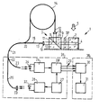
- the optical measuring device has an optical sensor 1 which contains a transparent sensor body 2 and a polarization splitter cube 3.
- An optical delay plate 37 which is preferably designed as an X / 8 plate, can be arranged between the sensor body 2 and the polarization splitter cube 3. Such a delay plate can also be arranged between sensor body 2 and mirror 4.
- the sensor body 2 shown in the figure is a voltage-optical sensor body, which is made of a translucent solid material such as e.g. can consist of quartz glass or translucent plastic.
- a mirror 4 is attached to the side of the sensor body 2 facing away from the polarization splitter cube 3.
- a pressure P acts on the sensor body 2 in such a way that the main voltage axes formed form an angle of 45 ° with the plane of the drawing in the area of the sensor body 2 which is irradiated with light.
- the sensor body 2 can also be made of yttrium iron garnet, which changes the polarization state of light depending on a magnetic field acting on the sensor body 2, of lithium niobate, which changes the polarization state of light depending on an electrical field, or also of lithium tantalate exist that changes the polarization state of light depending on the temperature of the sensor body 2.
- the sensor body 2 can consist of crystalline quartz, which also changes the polarization state of light as a function of the temperature.
- the polarization splitter cube 3 consists of two 90 ° prisms 9 and 10 made of flint glass, which are cemented together via a graduation layer 11. This reflects the linearly polarized part of the light radiated into the polarization divider cube 3 which is perpendicular to the plane of the drawing and allows the linearly polarized part of the light which swings horizontally to the plane of the drawing to pass through.
- the division layer 11 is formed from a plurality of layers of dielectric material, which can alternately consist of zinc sulfide and cryolite, for example.
- the fiber ends 12 and 13 of an optical delay line 14 and an optical path 15 designed as an optical fiber are aligned so that their longitudinal axes are perpendicular to each other and perpendicular to an outer surface 16 and 17 of the polarization splitter cube 3.
- the light emitted from the fiber end 12 falls through a lens 18 perpendicular to the outer surface 16 and the light emitted from the fiber end 13 through the lens 19 perpendicular to the outer surface 17 into the polarization splitter cube 3.
- the sensor body 2 is arranged in such a way that both the light emitted by the fiber end 12 and reflected by the graduation layer 11 and the light radiated by the fiber end 13 and passing through the graduation layer 11 radiate through it.
- the light is reflected back from the mirror 4 onto the polarization splitter cube 3 in such a way that light is directed from the graduation layer 11 via the lens 18 onto the end face of the fiber end 12 and light which passes through the graduation layer 11 from the lens 19 onto the end face of the fiber end 13 is directed.
- the optical delay line 14 can be designed as a coil former, on which several layers of glass fiber cables are wound.
- the optical delay line 14 and the optical path 15, which is designed as an optical fiber, are connected to one another via an optical coupler 20, which in the exemplary embodiment shown in the figure is designed as a fiber coupler.
- the optical coupler 20 can, however, also be designed as a beam splitter with a semi-permeable mirror, which partially reflects light and couples it into the optical delay line 14, and partially allows it to pass, so that it is projected onto the polarization splitter cube 3 via the lens 19.
- An optical fiber as an optical path 15 is only required if the optical coupler 20, which is designed as a beam splitter, is arranged at a greater distance from the lens 19.
- the device elements 1 to 20 can be arranged in a housing.
- the optical coupler 20 is connected to the electro-optical converter unit 35, which contains an optical fiber branch 22 connected to the connecting fiber 21, of which a first connecting optical fiber 23, which is optically connected to a light receiver 24, and a second connecting optical fiber 25 branch off, which is optically connected to a light transmitter 26.
- the light guide branch 22 is designed in the embodiment shown in the figure as a fiber coupler.
- the light transmitter 26 is controlled by an electrical pulse generator 27.
- the light receiver 24 is connected to a demultiplexer 28, which divides the voltage pulses supplied in series by the light receiver 24 into three parallel output lines 29 using the voltage pulses supplied by the pulse generator 27 and feeds them to a computer 30.
- Delay plate 37 is a ⁇ / n plate.
- K means a calibration constant that depends on the structure of the measuring device.
- the evaluation circuit 36 contains a display device 31 which displays the pressure P determined by the computer 30.
- the pressure measurement value P can also be fed via a data bus (not shown in the figure) to a computer (also not shown) for further processing.
- a light-emitting diode 32 connected to the light transmitter 26 emits light pulses which are coupled by a lens 33 into the second connecting light conductor 25.
- the light-emitting diode 32 can be designed, for example, as a laser diode.
- a light pulse passes through the second connecting light guide 25 and the connecting fiber 21 and is divided by the optical coupler 20 between the optical path 15 and the optical delay line 14. Due to the longer signal path, the pulse passed through the delay line 14 leaves the fiber end 12 by the time period A t later the fiber end 13 as the pulse conducted via the optical path 15. This latter pulse first reaches the polarization splitter cube 3 via the lens 19, the division layer 11 of which allows the linearly polarized portion of this pulse which vibrates parallel to the plane of the drawing to pass through the optical delay plate 37 reaches the sensor body 2.
- the pulse passed through the optical delay line 14 passes via the lens 18 to the polarization splitter cube 3, the division layer 11 of which reflects the linearly polarized portion oscillating perpendicular to the plane of the drawing through the optical delay plate 37 onto the sensor body 2.
- An optical delay plate 37 has the effect that the pulses are already elliptically polarized when no pressure P acts on the sensor body 2.
- the major axis of the polarization ellipse of the undelayed light pulse is parallel to the plane of the drawing, while that of the light pulse delayed in the optical delay line by the time period AT is perpendicular to the plane of the drawing.
- the graduation layer 11 in each case allows the linearly polarized components of these two elliptically polarized pulses, which vibrate parallel to the plane of the drawing, which are subsequently coupled into the optical path 15 by the lens 19, and reflects the linearly polarized components of these two, which oscillate perpendicularly to the plane of the drawing elliptically polarized pulses onto the lens 18, which couples these pulses into the optical delay line 14.
- These two pulses arrive at the optical coupler 20 by the time period A t later than the light pulses guided through the optical path 15.
- a light pulse first arrives, which is emitted by the optical path 15 and coupled back into the optical path 15 and thus does not experience any time delay in the optical delay line 14.
- the intensity I of this pulse decreases with increasing pressure P.
- light pulses delayed by the time period A t arrive at the optical coupler 20, which are emitted on the one hand by the optical path 15 and coupled into the optical delay line 14 after passing through the optical sensor 1 and on the other hand emitted by the optical delay line 14 and in the optical path 15 are coupled in and their intensities I 2/2 are proportional to the size of the pressure P acting on the sensor body 2.
- a light pulse arrives at the optical coupler 20, which is emitted by the optical delay line 14 and fed back into the optical delay line 14 and which therefore has a time delay of 2. ⁇ t experiences. The intensity 13 of this pulse decreases with increasing pressure P.
- These three light pulses arriving one after the other at the optical coupler 20 are forwarded via the connecting fiber 21, the light guide branch 22 and the first connecting light guide 23 to the light receiver 24 which, for example by means of a photodiode 34, converts the light pulses into three serial voltage pulses with the amplitudes I ,, 12 and I 3 converts.
- These three voltage pulses are distributed by the demultiplexer 28 to the three output lines 29 and fed to the computer 30, which determines the pressure acting on the sensor body 2 from their amplitudes and supplies them to a display device 31.
Landscapes
- Physics & Mathematics (AREA)
- General Physics & Mathematics (AREA)
- Measuring Fluid Pressure (AREA)
- Optical Transform (AREA)
- Photometry And Measurement Of Optical Pulse Characteristics (AREA)
- Light Guides In General And Applications Therefor (AREA)
Applications Claiming Priority (2)
| Application Number | Priority Date | Filing Date | Title |
|---|---|---|---|
| DE3510704 | 1985-03-23 | ||
| DE19853510704 DE3510704A1 (de) | 1985-03-23 | 1985-03-23 | Optisches messgeraet |
Publications (3)
| Publication Number | Publication Date |
|---|---|
| EP0199384A2 true EP0199384A2 (fr) | 1986-10-29 |
| EP0199384A3 EP0199384A3 (en) | 1988-07-06 |
| EP0199384B1 EP0199384B1 (fr) | 1990-12-27 |
Family
ID=6266218
Family Applications (1)
| Application Number | Title | Priority Date | Filing Date |
|---|---|---|---|
| EP86200437A Expired - Lifetime EP0199384B1 (fr) | 1985-03-23 | 1986-03-19 | Appareil de mesure optique |
Country Status (4)
| Country | Link |
|---|---|
| US (1) | US4740081A (fr) |
| EP (1) | EP0199384B1 (fr) |
| JP (1) | JPS61223612A (fr) |
| DE (2) | DE3510704A1 (fr) |
Families Citing this family (30)
| Publication number | Priority date | Publication date | Assignee | Title |
|---|---|---|---|---|
| DE3817568C2 (de) * | 1987-05-25 | 1995-06-22 | Hitachi Ltd | Optischer Modulator mit einem supraleitenden Oxid |
| US5004911A (en) * | 1989-06-20 | 1991-04-02 | Honeywell Inc. | Time multiplexed fiber optic sensor |
| US5094534A (en) * | 1989-12-27 | 1992-03-10 | Dylor Corporation | Coherence selective fiber optic interferometric sensor system |
| US5107445A (en) * | 1990-12-04 | 1992-04-21 | Luxtron Corporation | Modular luminescence-based measuring system using fast digital signal processing |
| US5322361A (en) * | 1993-01-28 | 1994-06-21 | C.I. Systems (Israel) Ltd. | Method and apparatus for measuring temperature |
| CA2097781A1 (fr) * | 1993-06-04 | 1994-12-05 | Peter O. Paulson | Appareil et methode d'essai non destructif des structures |
| CA2122782C (fr) * | 1994-05-03 | 1999-07-27 | Wojtek J. Bock | Appareil et methode pour mesurer un parametre physique dans une fibre de detection tres birefringente |
| US5978003A (en) * | 1997-06-30 | 1999-11-02 | Imation Corp. | Belt position detection system for belt registration in an electrophotographic imaging system |
| US6867751B1 (en) * | 1998-12-30 | 2005-03-15 | Honeywell Inc. | Methods and apparatus for adjusting the display characteristics of a display unit |
| KR101059822B1 (ko) * | 2007-03-27 | 2011-08-26 | 삼성전자주식회사 | 화상 형성 장치 및 그 제어 방법 |
| EP3229010A3 (fr) | 2007-10-25 | 2018-01-10 | Washington University in St. Louis | Microscopie photo-acoustique confocale présentant une résolution latérale optique |
| DE102008026967B3 (de) * | 2008-06-05 | 2010-01-28 | Deutsches Zentrum für Luft- und Raumfahrt e.V. | Verfahren und Vorrichtung zum Messen der Temperatur unter einer Wärmedämmschicht |
| US8416421B2 (en) * | 2008-10-01 | 2013-04-09 | Washington University | Optical coherence computed tomography |
| WO2010080991A2 (fr) | 2009-01-09 | 2010-07-15 | Washington University In St. Louis | Appareil d'imagerie photoacoustique miniaturisé comprenant un réflecteur rotatif |
| WO2011127428A2 (fr) | 2010-04-09 | 2011-10-13 | Washington University | Quantification de coefficients d'absorption optique à l'aide de spectres acoustiques dans la tomographie photoacoustique |
| DE102010061950A1 (de) * | 2010-11-25 | 2012-05-31 | Carl Zeiss Smt Gmbh | Verfahren sowie Anordnung zum Bestimmen des Erwärmungszustandes eines Spiegels in einem optischen System |
| US8997572B2 (en) | 2011-02-11 | 2015-04-07 | Washington University | Multi-focus optical-resolution photoacoustic microscopy with ultrasonic array detection |
| US9442095B2 (en) * | 2011-06-15 | 2016-09-13 | Northwestern University | Optical coherence photoacoustic microscopy |
| WO2014063005A1 (fr) | 2012-10-18 | 2014-04-24 | Washington University | Imagerie du cerveau par tomographie photoacoustique/thermoacoustique transcrânienne renseignée par des données d'images complémentaires |
| JP6452086B2 (ja) * | 2013-10-31 | 2019-01-16 | キヤノン株式会社 | 形状算出装置及び方法、計測装置、物品製造方法、及び、プログラム |
| WO2015077355A1 (fr) | 2013-11-19 | 2015-05-28 | Washington University | Systèmes et procédés de microscopie photo-acoustique de relaxation de grueneisen et mise en forme du front d'onde photo-acoustique |
| US20150377738A1 (en) * | 2014-06-27 | 2015-12-31 | Raytheon Bbn Technologies Corp. | System and method for optically reading a sensor array |
| CN106405447A (zh) * | 2016-08-26 | 2017-02-15 | 北京信息科技大学 | 一种利用纤芯失配干涉结构测量磁场的方法 |
| US11672426B2 (en) | 2017-05-10 | 2023-06-13 | California Institute Of Technology | Snapshot photoacoustic photography using an ergodic relay |
| EP3836831A4 (fr) | 2018-08-14 | 2022-05-18 | California Institute of Technology | Microscopie photoacoustique multifocale par l'intermédiaire d'un relais ergodique |
| WO2020051246A1 (fr) | 2018-09-04 | 2020-03-12 | California Institute Of Technology | Microscopie et spectroscopie photo-acoustique infrarouge à résolution améliorée |
| US11369280B2 (en) | 2019-03-01 | 2022-06-28 | California Institute Of Technology | Velocity-matched ultrasonic tagging in photoacoustic flowgraphy |
| US11986269B2 (en) | 2019-11-05 | 2024-05-21 | California Institute Of Technology | Spatiotemporal antialiasing in photoacoustic computed tomography |
| US12504363B2 (en) | 2021-08-17 | 2025-12-23 | California Institute Of Technology | Three-dimensional contoured scanning photoacoustic imaging and virtual staining |
| US12593986B2 (en) | 2023-04-12 | 2026-04-07 | California Institute Of Technology | Transmission mode-photoacoustic tomography of the human brain through an acoustic window |
Family Cites Families (5)
| Publication number | Priority date | Publication date | Assignee | Title |
|---|---|---|---|---|
| US3925727A (en) * | 1973-09-28 | 1975-12-09 | Bell Telephone Labor Inc | Optical sampling oscilloscope utilizing organ arrays of optical fibers |
| US4025195A (en) * | 1974-07-22 | 1977-05-24 | Itek Corporation | Image subtraction/addition system |
| GB1540907A (en) * | 1976-12-07 | 1979-02-21 | Standard Telephones Cables Ltd | System for obtaining data from a plurality of condition responsive optical devices |
| US4334781A (en) * | 1979-06-08 | 1982-06-15 | Tokyo Shibaura Denki Kabushiki Kaisha | Optical sensing system |
| ATE48033T1 (de) * | 1982-04-14 | 1989-12-15 | Univ Leland Stanford Junior | Fiber-optischer sensor zum detektieren sehr kleiner verschiebungen einer oberflaeche. |
-
1985
- 1985-03-23 DE DE19853510704 patent/DE3510704A1/de not_active Withdrawn
-
1986
- 1986-03-18 US US06/841,127 patent/US4740081A/en not_active Expired - Fee Related
- 1986-03-19 DE DE8686200437T patent/DE3676537D1/de not_active Expired - Lifetime
- 1986-03-19 EP EP86200437A patent/EP0199384B1/fr not_active Expired - Lifetime
- 1986-03-20 JP JP61063889A patent/JPS61223612A/ja active Pending
Also Published As
| Publication number | Publication date |
|---|---|
| JPS61223612A (ja) | 1986-10-04 |
| EP0199384A3 (en) | 1988-07-06 |
| EP0199384B1 (fr) | 1990-12-27 |
| US4740081A (en) | 1988-04-26 |
| DE3510704A1 (de) | 1986-09-25 |
| DE3676537D1 (de) | 1991-02-07 |
Similar Documents
| Publication | Publication Date | Title |
|---|---|---|
| EP0199384B1 (fr) | Appareil de mesure optique | |
| DE3203347C2 (de) | Sensoranordnung zur Messung eines physikalischen Parameters | |
| DE68922951T2 (de) | Elektrooptisches Spannungsdifferenz-Messverfahren und -Gerät in einem Messsystem für phasenverschobene Signale. | |
| DE3609507C2 (de) | Faseroptisches Interferometer | |
| EP0857980A1 (fr) | Télémètre | |
| EP0706661B1 (fr) | Procede optique permettant de mesurer un courant alternatif electrique compense en temperature et dispositif de mise en ouvre dudit procede | |
| EP0445362B1 (fr) | Dispositif de mesure d'une induction magnétique | |
| DE3833930C2 (fr) | ||
| CH620771A5 (fr) | ||
| DE69109535T2 (de) | Gerichteter, polarimetrischer Feldsensor. | |
| EP0096262B1 (fr) | Sensor à fibre optique pour mesurer des grandeurs dynamiques | |
| EP0116131A2 (fr) | Transducteur à fibres optiques | |
| DE3145795A1 (de) | "faseroptisches messgeraet zum messen physikalischer groessen" | |
| DE3626639A1 (de) | Fotoelektrischer messwandler, insbesondere beschleunigungsmesser | |
| DE2113477A1 (de) | Optischer Abtaster und Messanordnungen mit solchen optischen Abtastern | |
| EP0164599B1 (fr) | Dispositif pour la mesure de la vitesse de rotation | |
| EP0360346B1 (fr) | Procédé et dispositif de mesure de force par des moyens optiques | |
| DE4133131C2 (de) | Anordnung zum Bestimmen von die Lichtintensität beeinflussenden chemischen und/oder physikalischen Größen | |
| EP1151242B1 (fr) | Detecteur et procede pour detecter des variations de distance | |
| EP0412309B1 (fr) | Gyroscope à fibre optique du type Sagnac | |
| DE3148738A1 (de) | Einrichtung zum messen physikalischer groessen | |
| DE19548920C2 (de) | Optischer Sensor und Verwendung eines solchen Sensors in einer Prozeß-Meßgeräteeinrichtung | |
| DE2645997A1 (de) | Temperaturmesseinrichtung | |
| DE3903881C1 (fr) | ||
| EP0226652A1 (fr) | Capteur |
Legal Events
| Date | Code | Title | Description |
|---|---|---|---|
| PUAI | Public reference made under article 153(3) epc to a published international application that has entered the european phase |
Free format text: ORIGINAL CODE: 0009012 |
|
| AK | Designated contracting states |
Kind code of ref document: A2 Designated state(s): DE FR GB |
|
| RAP1 | Party data changed (applicant data changed or rights of an application transferred) |
Owner name: N.V. PHILIPS' GLOEILAMPENFABRIEKEN Owner name: PHILIPS PATENTVERWALTUNG GMBH |
|
| PUAL | Search report despatched |
Free format text: ORIGINAL CODE: 0009013 |
|
| AK | Designated contracting states |
Kind code of ref document: A3 Designated state(s): DE FR GB |
|
| 17P | Request for examination filed |
Effective date: 19881215 |
|
| 17Q | First examination report despatched |
Effective date: 19891222 |
|
| GRAA | (expected) grant |
Free format text: ORIGINAL CODE: 0009210 |
|
| AK | Designated contracting states |
Kind code of ref document: B1 Designated state(s): DE FR GB |
|
| REF | Corresponds to: |
Ref document number: 3676537 Country of ref document: DE Date of ref document: 19910207 |
|
| PGFP | Annual fee paid to national office [announced via postgrant information from national office to epo] |
Ref country code: GB Payment date: 19910301 Year of fee payment: 6 |
|
| PGFP | Annual fee paid to national office [announced via postgrant information from national office to epo] |
Ref country code: FR Payment date: 19910322 Year of fee payment: 6 |
|
| ET | Fr: translation filed | ||
| GBT | Gb: translation of ep patent filed (gb section 77(6)(a)/1977) | ||
| PGFP | Annual fee paid to national office [announced via postgrant information from national office to epo] |
Ref country code: DE Payment date: 19910523 Year of fee payment: 6 |
|
| PLBE | No opposition filed within time limit |
Free format text: ORIGINAL CODE: 0009261 |
|
| STAA | Information on the status of an ep patent application or granted ep patent |
Free format text: STATUS: NO OPPOSITION FILED WITHIN TIME LIMIT |
|
| 26N | No opposition filed | ||
| PG25 | Lapsed in a contracting state [announced via postgrant information from national office to epo] |
Ref country code: GB Effective date: 19920319 |
|
| GBPC | Gb: european patent ceased through non-payment of renewal fee | ||
| PG25 | Lapsed in a contracting state [announced via postgrant information from national office to epo] |
Ref country code: FR Effective date: 19921130 |
|
| PG25 | Lapsed in a contracting state [announced via postgrant information from national office to epo] |
Ref country code: DE Effective date: 19921201 |
|
| REG | Reference to a national code |
Ref country code: FR Ref legal event code: ST |