EP0199395A2 - Anordnung für Stahlbau im allgemeinen, insbesondere für Fachwerkbau, hergestellt mittels Profileisen und Verbindungselemente - Google Patents
Anordnung für Stahlbau im allgemeinen, insbesondere für Fachwerkbau, hergestellt mittels Profileisen und Verbindungselemente Download PDFInfo
- Publication number
- EP0199395A2 EP0199395A2 EP86200511A EP86200511A EP0199395A2 EP 0199395 A2 EP0199395 A2 EP 0199395A2 EP 86200511 A EP86200511 A EP 86200511A EP 86200511 A EP86200511 A EP 86200511A EP 0199395 A2 EP0199395 A2 EP 0199395A2
- Authority
- EP
- European Patent Office
- Prior art keywords
- leg
- angle iron
- plate
- fastened
- structure according
- Prior art date
- Legal status (The legal status is an assumption and is not a legal conclusion. Google has not performed a legal analysis and makes no representation as to the accuracy of the status listed.)
- Granted
Links
Images




Classifications
-
- C—CHEMISTRY; METALLURGY
- C03—GLASS; MINERAL OR SLAG WOOL
- C03B—MANUFACTURE, SHAPING, OR SUPPLEMENTARY PROCESSES
- C03B23/00—Re-forming shaped glass
- C03B23/04—Re-forming tubes or rods
- C03B23/09—Reshaping the ends, e.g. as grooves, threads or mouths
-
- E—FIXED CONSTRUCTIONS
- E04—BUILDING
- E04C—STRUCTURAL ELEMENTS; BUILDING MATERIALS
- E04C3/00—Structural elongated elements designed for load-supporting
- E04C3/02—Joists; Girders, trusses, or trusslike structures, e.g. prefabricated; Lintels; Transoms; Braces
- E04C3/04—Joists; Girders, trusses, or trusslike structures, e.g. prefabricated; Lintels; Transoms; Braces of metal
- E04C3/08—Joists; Girders, trusses, or trusslike structures, e.g. prefabricated; Lintels; Transoms; Braces of metal with apertured web, e.g. with a web consisting of bar-like components; Honeycomb girders
-
- B—PERFORMING OPERATIONS; TRANSPORTING
- B01—PHYSICAL OR CHEMICAL PROCESSES OR APPARATUS IN GENERAL
- B01L—CHEMICAL OR PHYSICAL LABORATORY APPARATUS FOR GENERAL USE
- B01L3/00—Containers or dishes for laboratory use, e.g. laboratory glassware; Droppers
-
- E—FIXED CONSTRUCTIONS
- E04—BUILDING
- E04C—STRUCTURAL ELEMENTS; BUILDING MATERIALS
- E04C3/00—Structural elongated elements designed for load-supporting
- E04C3/02—Joists; Girders, trusses, or trusslike structures, e.g. prefabricated; Lintels; Transoms; Braces
- E04C3/04—Joists; Girders, trusses, or trusslike structures, e.g. prefabricated; Lintels; Transoms; Braces of metal
-
- E—FIXED CONSTRUCTIONS
- E04—BUILDING
- E04C—STRUCTURAL ELEMENTS; BUILDING MATERIALS
- E04C3/00—Structural elongated elements designed for load-supporting
- E04C3/30—Columns; Pillars; Struts
- E04C3/32—Columns; Pillars; Struts of metal
-
- E—FIXED CONSTRUCTIONS
- E04—BUILDING
- E04C—STRUCTURAL ELEMENTS; BUILDING MATERIALS
- E04C3/00—Structural elongated elements designed for load-supporting
- E04C3/02—Joists; Girders, trusses, or trusslike structures, e.g. prefabricated; Lintels; Transoms; Braces
- E04C3/04—Joists; Girders, trusses, or trusslike structures, e.g. prefabricated; Lintels; Transoms; Braces of metal
- E04C2003/0404—Joists; Girders, trusses, or trusslike structures, e.g. prefabricated; Lintels; Transoms; Braces of metal beams, girders, or joists characterised by cross-sectional aspects
- E04C2003/0408—Joists; Girders, trusses, or trusslike structures, e.g. prefabricated; Lintels; Transoms; Braces of metal beams, girders, or joists characterised by cross-sectional aspects characterised by assembly or the cross-section
- E04C2003/0413—Joists; Girders, trusses, or trusslike structures, e.g. prefabricated; Lintels; Transoms; Braces of metal beams, girders, or joists characterised by cross-sectional aspects characterised by assembly or the cross-section being built up from several parts
-
- E—FIXED CONSTRUCTIONS
- E04—BUILDING
- E04C—STRUCTURAL ELEMENTS; BUILDING MATERIALS
- E04C3/00—Structural elongated elements designed for load-supporting
- E04C3/02—Joists; Girders, trusses, or trusslike structures, e.g. prefabricated; Lintels; Transoms; Braces
- E04C3/04—Joists; Girders, trusses, or trusslike structures, e.g. prefabricated; Lintels; Transoms; Braces of metal
- E04C2003/0404—Joists; Girders, trusses, or trusslike structures, e.g. prefabricated; Lintels; Transoms; Braces of metal beams, girders, or joists characterised by cross-sectional aspects
- E04C2003/0426—Joists; Girders, trusses, or trusslike structures, e.g. prefabricated; Lintels; Transoms; Braces of metal beams, girders, or joists characterised by cross-sectional aspects characterised by material distribution in cross section
- E04C2003/0439—Joists; Girders, trusses, or trusslike structures, e.g. prefabricated; Lintels; Transoms; Braces of metal beams, girders, or joists characterised by cross-sectional aspects characterised by material distribution in cross section the cross-section comprising open parts and hollow parts
Definitions
- the object of the present invention is a structure for metal constructions in general, in particular for trestlework type structures, accomplished by means of section bars and jointing elements.
- the element jointing the stringers and the section bars, or the wall rods and the stringer be fastened to the same stringer by means of bolts, rivets or welding beads positioned along a line coincident with the barycentric axis of the stringer, or on two lines parallel to the barycentric axis of the stringer, and lying on a plane passing through the barycentric axis, but not on the same side of the barycentric axis.
- section bar for stringers or uprights of trestlework girders or of other metal structures is disclosed, which section bar offers several advantages over other section bars known from the prior art, such as angle irons, H-beams, channels, and so forth.
- this section bar of the prior art which is constituted by an angle iron with equal legs, each one of which is extended at its free end with a first extension length positioned at right angle relatively to the relating leg in the same direction as of the other leg, and with a second extension length positioned at right angle relatively to the first extension leg in such a direction as to depart from the other leg, with said first and second extension lengthes having each a width equal to half width of a leg of the angle iron, allows an easy fastening of the connections or jointing elements for wall rods with perfect symmetry between the two sides, has a large inertial radius and can hence have a reduced weight of its own, and allows achieving that the action lines of the forces acting through the connections or jointing elements fastening the wall rods to the stringer converge and cross each other on the barycentric axis of the section bar.
- connection or jointing elements joining these known section bars and the wall rods are indicated in the afore said patent as plates, angle slabs or the like, to be fastened by means of bolts, rivets or welding beads to said second extension lengthes of the legs of the angle iron.
- the action lines of the forces acting through these connections on the section bar converge and cross each other on the barycentric axis of the section bar.
- Purpose of the present invention is hence to provide a structure for mechanical constructions in general, in particular for trestlework constructions, accomplished by means of profile bars and jointing elements which, while maintaining the advantages of the angle iron of the above mentioned European Patent N. 0023373 of 12.10.83 allows a correct connection of said section bars with each other, and of the section bars with the wall rods, without inducting in the section bar a parasite flexural moment and other local actions which can deform the cross section shape of the same section bar.
- such a structure is proposed for the metal constructions in general, and in particular for trestlework constructions, accomplished by -means of section bars and jointing elements, characterized in that it comprises at least one angle iron having equal legs, each of which legs is extended at its free end with a first extension length positioned at right angle relatively to the related leg in the same direction as of the other leg, and with a second extension leg positioned at right angle relatively to the first extension length in such a direction as to depart from the other leg, with said first and second extension lengthes having each one a width substantially equal to half width of a leg of the angle iron, and at least a jointing element constituted by at least one plate suitable to be fastened to said angle iron at least in correspondence of the inner surface of one of its legs, and in correspondence of the inner surface of the second extension length of its second leg.
- a so constructed structure allows connecting in a correct way the section bars with each other, or connecting with the section bars wall rods on a plane parallel to the planes of said second leg of the angle iron and of the related second extension length.
- the jointing element can be constituted by one single and simple plate butt-fastened on one side by means of a welding bead to the inner surface of the said first leg of the angle iron, and fastened on the other side by welding, bolting or riveting to the inner surface of the second extension length of the second leg of the angle iron.
- a plate can be provided ending, at an end, with a second plate, so as to form a T-shaped element, wherein the second plate of such an element is destined to be fastened by suitable means, e.g., bolts, rivets or the like, to the inner surface of a leg of the angle iron, possibly also by means of a double row of fastening means, whilst the first plate, or the core of the T-shaped element, is destined to be fastened by means of similar fastening means, to the inner surface of the second extension length of the other leg of the angle iron.
- suitable means e.g., bolts, rivets or the like
- the jointing element shall be so accomplished as to be suitable to be fastened on one side in correspondence of the inner surfaces of both second extension lengthes of the angle iron, and on the other side at least in correspondence of the inner surface of one of the legs of said angle iron.
- the structure provided according to the present invention allows achieving the fulfillment of the conditions necessary for the correct transmission of the forces in the connection points of section bars or stringers and from the wall rods - (braces, uprights and crosspieces) to the section bar or stringer, without undesired effects due to the parasite flexural moments.
- the connection between stringers and wall rods occurs through an element distinct from both the stringer and the wall rod, an indirect connection is achieved, with the consequent further advantage that each element converging in the knot bears only the actions competing to it, in that it is the jointing element that which receives the actions exerted by the various rods, and discharges them correctly.
- the jointing element provided in the structure according to the invention can be used also as an element for the stiffening of the angle iron in points wherein no other elements converge.
- a block possibly provided with lightening cavities, can be used, having at least two faces perpendicular to each other, destined to be fastened to the inner surfaces of the two legs of the angle iron, and provided with two flat projections parallel to said two perpendicular faces of the block, and protruding from other two faces of the same block, said flat projections being destined to be fastened to the inner surfaces of the second extension lengthes of the angle iron.
- the block of the jointing element being inserted inside the space bound by the two legs and by the two first extension lengthes of the angle iron, renders the cross section of the section bar particularly indeformable, besides allowing the wall rods to be connected on two planes perpendicular to each other.
- the jointing elements can also longitudinally end with a plate,, or with any other generic element intended to abut against the end of the angle iron to allow any other section bar to be connected to it by means of bolts, rivets, or welds.
- the jointing elements provided in the structure according to the invention can be obtained, in case they do not consist of a simple plate, by means of the welding of plates, or by casting, forging, extrusion, or by any other procedures.
- the plate-(s) of the jointing element intended for being fastened to the inner surfaces of the second extension length(es) of the legs of the section bar are not precisely centred on the centre of gravity of the same section bar, remaining off-centred relatively to it by a distance equal to the sum formed by the half-width of the second extension lengthes of the legs of the section bar and by the half-thickness of the plates of the jointing element destined to be fastened to the inner surfaces of the said second extension lengthes.
- the first extension lengthes of the two legs of the angle iron can each be given a width equal to half width of a leg of the section bar, lessened by a value corresponding to the sum formed by half-thickness of the second extension lengthes of the legs of the section bar, plus the half-width of the plates of the jointing element destined to be fastened to the inner surfaces of said second extension lengthes, and the second extension lengthes of the two legs of the section bar can each be given a width equal to the half-width of a leg of the section bar, increased by the value of the said sum.
- the plate(s) of the jointing element can be fastened to the inner surfaces of the second extension lengthes of the legs of the angle iron, so that the forces transmitted by the wall rods connected to said plate(s) pass through the barycentric axis of the angle section bar, but the position of the barycentre of the section bar remains unchanged relatively to the position of the barycentre of an angle iron, wherein the first and second extension lengthes of the two legs of the section bar have a width equal to half width of a leg.
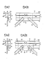
- a structure which comprises an angle iron, generally indicated with 10, and a jointing element, generally indicated with 16.
- the angle iron 10 has two legs 11 and 11 a of equal width, and each of these legs is extended at its free end with first extension length 12 and respectively 12a, and with a second extension length 13 and respectively 13a.
- the first extension lengthes 12 and 12a are perpendicular to their respective legs 11, 11a of the angle iron 10 and are positioned in the same direction as of the other respective leg 11 a, 11 of the section bar.
- the second extension lengthes 13 and 13a are perpendicular to their respective first extension lengthes 12 and 12a and are positioned in such directions as to depart from the respective other leg 11a, 11 of the angle iron 10.
- Each of said first and second extension lengthes 12, 12a and 13, 13a of the section bar 10 has a width equal to half width of a leg 11 or 11 a of the same section bar.
- the jointing element 16 is constituted, in this simplest form of embodiment, by a simple plate 17 butt-welded in 18 to the inner surface of the leg 11 a of the section bar 10, and abutting against the inner surface of the second extension length 13 of the other leg 11 of the section bar, to which length 13 it is welded by means of a welding bead 19.
- the junction element 16 can be used to connect to the section bar or stringer 10 two elements 14, 15, suitably fastened, e.g., also welded, to the junction element 16 and so inclined that their barycentric axes A-A and respectively B-B cross each other on the barycentric axis X-X of the section bar 10 (see fig. 1 a).
- FIG. 2-2a Another form of embodiment of the structure, wherein always the same angle iron 10 as shown in Fig. 1-1a can be used, is shown in fig. 2-2a, and contains a T-shaped jointing element 20, comprising a plate 21 with which a second plate 22 perpendicular to the first plate 21 has been made butt- solid, e.g., by butt-welding.
- the plate 22 is fastened to the inner surface of the leg 11 a of the section bar 10, e.g., by two rivets or bolts 23, 24 lined-up on the centre-plane of the plate 21, and the plate 21 is fastened to the inner surface of the second extension length 13 of the leg 11 of the section bar 10 by means of a couple of rivets or bolts 25, 26.
- the elements 14 and 15 are fastened by means of the same rivets or bolts 25, 26 and further rivets 27, 28, so that their barycentric axes A-A and B-B converge on the barycentric axis X-X of the profile bar 10.
- a form of embodiment analogue to that shown in fig 2-2a is shown in fig. 3-3a and is different from the foregoing only because the plate 22 of the T-shaped jointing eiement 20 is fastened on the inner surface of the leg 11 a of the section bar 10 by means of two rows of rivets or bolts 23 , 24 and 23a, 24a, with the rivets or bolts 23 and 24 and 23a and 24a being respectively positioned along two lines parallel to the barycentric axis X-X of the section bar 10 and lying on parallel and equidistant planes, but on opposite sides, relatively to the centre-plane of the plate 21 of the T-shaped jointing element 20.
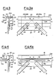
- Figs. 4-4a show an example of structure providing the jointing to the section bar or stringer 10 as of the former figures, of wall rods on two perpendicular planes, to provide a tridimensional network beam.
- the jointing element 29, in a simpler form can be constituted by a T-shaped element with a plate 30 butt-fastened, e.g., by means of welding beads 31, to a second plate 32.
- the plate 30 is butt-fastened, e.g., by means of a welding bead 33, to the inner surface of the leg 11 a of the section bar 10, abuts against the inner surface of the second extension length 13 of the other leg 11 of the section bar 10 and is fastened to this length 13 by, e.g., a welding bead 34.
- the plate 32 abuts against the inner surface of the second extension length 13a of the leg 11 a of the section bar 10 and is fastened to this length 13a by, e.g., a welding bead 35.
- a welding bead 35 As it can be seen,in this case, to the plate 30 of the jointing element 29, two elements 14, 15, which lie on a plane parallel to the leg 11 of the section bar 10, can be suitably fastened, e.g., by welding, whilst to the plate 32 of the junction element 29 other two elements 14a, 15a, which lie on a plane perpedn- dicular to the plane containing the elements 14 and 15 can be suitably fastened, e.g., by welding.
- Figs. 5-5a and 6-6a are analogue to those of Figs. 4-4a, with a jointing element 29 for the connection of elements or wall rods 14-15 and 14a-15a on two perpendicular planes, and these examples of practical embodiment resemble, as for the way of fastening the jointing element 29 to the inner surface of the leg 11 a of the section bar 10, to the forms of embodiment shown in figs. 2-2a and 3-3a respectively.
- the parts equal or having the same functions as in the former examples of practical embodiment are hence indicated with the same reference numerals.
- the reference numerals 25a-26a and 27a-28a are added to indicate the rivets or bolts for the fastening respectively of the plate 32 to the inner surface of the second extension length 13a of the leg 11 a of the section bar 10, and of the elements 14a, 15a to the plate 32 of the jointing element 29 (see Figs. 5-5a and Figs. 6-6a).
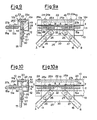
- Figs. 7-7a show a further example of practical embodiment similar to that shown in Figs. 5-5a, with the only difference that the plate 22 of the jointing element 29, instead of being fastened to the leg 11 a of the section bar 10 by means of rivets or bolts 23, 24, is equipped with bolts 36, 37 suitable to be passed through suitable bores 38, 39 provided on the leg 11 a of the section bar 10, on said bolts 36, 37 fastening nuts 40, 41 being screwed down.
- FIG. 8-8a A further possibility analogue to that as of Figs. 7-7a is shown in Figs, 8-8a, wherein the plate 22 performs the function of nut, by being provided with threaded bores 42, 43, into which bolts 44, 45, passing through corrsponding non-threaded holes provided on the leg 11 a of the section bar 10 are screwed down.
- Proper clearances 46, 47 are provided in this case in the plate 30, to allow the bolts 44, 45 to be completely screwed down in the threaded bores 42, 43 of the plate 22 of the jointing element 29.
- Figs. 9-9a show an example of practical embodiment similar to that as of Figs. 6-6a, with the only difference that the two plates 30 and 32 of the jointing element 29, instead of being jointed by welding, are connected by riveting or bolting.
- the plate 32 is provided, by butt-fastening, with a perpendicular plate 48, which abuts against the plate 30 and is made solid with it by means of rivets or bolts 49.
- Figs. 10-10a show an example of practical embodiment analogue to that of Figs. 5-5a, wherein the jointing element 29 is provided, as an extension of the plate 32, and on the opposite side of the plate 30, with a further plate 50, the end of which is butt-fastened to a perpen dicular plate 51, abutting against the inner surface of the leg 11 of the section bar 10, to which leg 11 the plate 51 is fastened by means of rivets or bolts 52 in a way analogue to that by which the plate 22 perpendicular to the plate 30 is fastened to the leg 11 a of the section bar 10.
- the fastening of the plate 51 to the leg 11 of the section bar 10 could be accomplished also by means of a double row of rivets or bolts, as shown in Figs, 6-6a for the fastening of the plate 22 to the leg 11 a of the section bar 10.
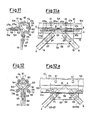
- Figs. 11-11 a show an example of practical embodiment in which a jointing element 53 is provided, which is constituted by a block 54, suitably provided with lightening cavities 55, and having two outer faces 56, 57 perpendicular to each other, destined to abut against the inner surfaces of the legs 11 and 11 a of the section bar 10.
- two plates 58, 59 are moreover provided, destined to abut respectively against the inner surfaces of the second extension lengthes 13, 13a of the legs 11, 11 a of the section bar 10, to which lengthes 13, 13a the plates 58, 59 are fastened by means of rivets or bolts 25, 26 and respectively 25a, 26a.
- the wall rods 14, 15 and 14a, 15a are in their turn fastened by means of the rivets or bolts 25, 26, 25a, 26a, as well as by means of rivets or bolts 27, 28, 27a, 28a, as already described with reference to Figs. 5-5a.
- the block 54 is fastened in its turn to the legs 11, 11 a of the section bar 10 by means of bolts 60, 61 passing through suitable bores provided on said legs 11, 11 a and screwed down in threaded bores provided in the same block.
- the shaping of the block 54 can be different from that shown, in order to obtain a higher lightening, and to secure a regular force line flow, provided that the block has the two perpendicular faces 56, 57 destined to abut against the inner surfaces of the legs 11, 11 a of the section bar 10.
- the block 54 could however be also solid.
- a block 54 of type analogue to that of Figs. 11-11 a a protruding plate 62 positioned on a centre-plane between the plates 58 and 59.
- a block 54 is mounted on and fastened to the section bar 10 by means of bolts 60, 61 and rivets or bolts 25, 25a, as shown in Fig. 12, the plate 62 of the block 54 lies. on a plane passing through the gravity centre of the section bar 10 and inclined by 45° relatively to the legs 11, 11 a of the same section bar.
- a jointing element 63 of this kind allows connecting to the section bar 10 other elements, such as the elements 64, 65 and 66, 67, to be fastened by means of suitable rivets or bolts 68-69 and 70-71 to said plate 62.
- junction elements illustrated up to now can longitudinally end with a plate 72, as shown in Figs. 13-13a for a junction element 29 of the type shown in Figs 6-6a, to allow to the section bar 10 another section bar whatsoever, e.g., an H-beam 73, to be connected, by rivets or bolts 74, 75, or by welds.
- This plate 72 is butt-welded to the plates 30, 32 and 22 of the jointing element 29 and frontally abuts against the end of the section bar 10.
- the fastening of the jointing element 29 to the section bar 10 can occur as already described with reference to Figs. 6-6a.
- the plate 72 another suitable element could be provided.
- Figs 14-14a show to exemplifying purposes the use of a jointing element 29 analogue to that shown in Figs. 10-10a, to the purpose of butt-connecting two section bars 10 and 10a with each other.
- the plate 22 of the jointing element 29 is fastened by means of rivets or bolts 23, 24 and 23a, 24a to the inner surfaces of the legs 11 a of the two near section bars 10 and 10a
- the plate 51 is fastened by rivets or bolts 52 to the inner surface of the legs 11
- the plate 30 is fastened by rivets or bolts 25 to the inner surfaces of the second extension lengthes 13 of the legs 11 of the two section bars 10, 10a
- the plate 32 is fastened by rivets or bolts 25a to the inner surfaces of the second extension lengthes 13a of the legs 11 a of the two section bars 10, 10a.
- junction elements as disclosed can be obtained by welding plates, or by casting, forging, extrusion, on in any other way from metal materials, such as iron, steel, aluminium or their alloys.
- junction elements can be swapped and/or combined with each other in various patterns.
- the angle iron 80 shown in Fig. 15 has it too two equal legs 81 and 81a, which legs are each extended, in correspondance of their free ends, with a first extension length 82 and respectively 82a positioned at right angle relatively to its related leg 81 and respectively 81 a in the same direction as of the other leg 81 a and respectively 81, and with a second extension length 83 and respectively 83a positioned at right angle relatively to the first extension length 82 and respectively 82a in such a direction as to depart from the other leg 81 a and respectively 81.
- first and second extension lengthes 82, 82a and 83, 83a do not have each a width exactly equal to half width of one leg 81 or 81 a of the angle iron 80, but the first extension lengthes are slightly less wide and the second extension lengthes are correspondigly wider.
- the lessening and respectively the increase in width of the said extension lengthes depend, on one hand, on the wall thickness of these lengthes and hence of the whole angle iron (because its legs and extension lengthes have the same part thickness), and, on the other hand, on the wall thickness of the plates of the junction element destined to be fastened to the inner surfaces of the second extension lengthes of the same angle iron.
- the first extension lengthes 82, 82a of the legs 81, 81 a of the angle iron 80 have each a width equal to half width of a leg 81 or 81 a of the section bar, lessened by a value corresponding to the sum formed by the half-thickness of the second extension lengthes 83, 83a of the legs of the section bar and by the half-thicknesstof the plates 30, 32 of the junction element 29 destined to be fastened to the inner surfaces of said second extension lengthes 83 and respectively 83a.
- a junction element 29 of the type as described above with reference to Figs. 10-10a is fastened.
- FIG. 16 A form of embodiment of the section bar having equal legs, similar to that shown in Fig. 15 is shown in Fig. 16 too.
- This latter form of embodiment, for which the same reference numerals as of Fig. 15 have been used, is different from this latter only in that the second extension lengthes 83, 83a have in correspondence of their free ends short lengthes 84, 84a bent rearwards at a right angle.
- both the width of the second extension lengthes of the legs of the angle iron, and that of said lengthes bent rearwards must be calculated in such a way as to keep unchanged the centre of gravity C.G. of the same section bar.
- the advantage of such a section bar consists in that it has its edges stiffened and shows hence a higher strength to flexural stresses.
- angle iron 80 as the angle iron 10, can be obtained by cold-bending, hot-rolling or extrusion, of steel or of aluminium or of their alloys.
Landscapes
- Engineering & Computer Science (AREA)
- Architecture (AREA)
- Civil Engineering (AREA)
- Structural Engineering (AREA)
- Chemical & Material Sciences (AREA)
- Materials Engineering (AREA)
- Organic Chemistry (AREA)
- Health & Medical Sciences (AREA)
- Clinical Laboratory Science (AREA)
- Chemical Kinetics & Catalysis (AREA)
- Joining Of Building Structures In Genera (AREA)
- Manufacturing Of Electrical Connectors (AREA)
- Conductive Materials (AREA)
- Rod-Shaped Construction Members (AREA)
- Connection Of Plates (AREA)
- Glass Compositions (AREA)
- Superconductors And Manufacturing Methods Therefor (AREA)
- Manufacture And Refinement Of Metals (AREA)
- Ceramic Products (AREA)
- Baking, Grill, Roasting (AREA)
- Connections Effected By Soldering, Adhesion, Or Permanent Deformation (AREA)
- Mutual Connection Of Rods And Tubes (AREA)
- Clamps And Clips (AREA)
Priority Applications (1)
| Application Number | Priority Date | Filing Date | Title |
|---|---|---|---|
| AT86200511T ATE53422T1 (de) | 1985-04-05 | 1986-03-27 | Anordnung fuer stahlbau im allgemeinen, insbesondere fuer fachwerkbau, hergestellt mittels profileisen und verbindungselemente. |
Applications Claiming Priority (2)
| Application Number | Priority Date | Filing Date | Title |
|---|---|---|---|
| IT20270/85A IT1184403B (it) | 1985-04-05 | 1985-04-05 | Struttura per costruzioni metalliche in genere,in particolare per costruzioni a traliccio,realizzata mediante profilati ed elementi di giunzione |
| IT2027085 | 1985-04-05 |
Publications (3)
| Publication Number | Publication Date |
|---|---|
| EP0199395A2 true EP0199395A2 (de) | 1986-10-29 |
| EP0199395A3 EP0199395A3 (en) | 1987-08-26 |
| EP0199395B1 EP0199395B1 (de) | 1990-06-06 |
Family
ID=11165307
Family Applications (1)
| Application Number | Title | Priority Date | Filing Date |
|---|---|---|---|
| EP86200511A Expired - Lifetime EP0199395B1 (de) | 1985-04-05 | 1986-03-27 | Anordnung für Stahlbau im allgemeinen, insbesondere für Fachwerkbau, hergestellt mittels Profileisen und Verbindungselemente |
Country Status (20)
| Country | Link |
|---|---|
| US (1) | US4680912A (de) |
| EP (1) | EP0199395B1 (de) |
| JP (1) | JPH0754013B2 (de) |
| KR (1) | KR900006918B1 (de) |
| CN (1) | CN1007995B (de) |
| AT (1) | ATE53422T1 (de) |
| AU (1) | AU585000B2 (de) |
| BR (1) | BR8601557A (de) |
| CA (1) | CA1281883C (de) |
| DD (1) | DD244589A5 (de) |
| DE (1) | DE3671774D1 (de) |
| ES (1) | ES8702559A1 (de) |
| HR (1) | HRP920996A2 (de) |
| IN (1) | IN165936B (de) |
| IT (1) | IT1184403B (de) |
| PL (1) | PL153539B1 (de) |
| PT (1) | PT82305B (de) |
| SU (1) | SU1600636A3 (de) |
| YU (1) | YU46523B (de) |
| ZA (1) | ZA862522B (de) |
Cited By (1)
| Publication number | Priority date | Publication date | Assignee | Title |
|---|---|---|---|---|
| WO2000031358A1 (en) * | 1998-11-25 | 2000-06-02 | Sistem Engineering S.R.L. | Structure made of web members for trusses |
Families Citing this family (5)
| Publication number | Priority date | Publication date | Assignee | Title |
|---|---|---|---|---|
| US5123587A (en) * | 1991-06-11 | 1992-06-23 | Owen Joist Corporation | Method and apparatus for making steel joists |
| NL1018088C2 (nl) * | 2001-05-17 | 2002-11-19 | Wuestman Tuindecoraties B V | Verbinding voor wandelementen. |
| DE102004054582A1 (de) * | 2004-11-11 | 2006-05-24 | Siemens Ag | Verfahren zum Verbinden von Bauteilen durch Nieten oder Schrauben und Laserschweißen |
| USD557429S1 (en) * | 2006-08-16 | 2007-12-11 | Environmental Air Systems, Inc. | Wall extrusion |
| RU2756262C1 (ru) * | 2020-12-10 | 2021-09-28 | Федеральное государственное бюджетное образовательное учреждение высшего образования "Казанский государственный архитектурно-строительный университет" (КазГАСУ) | Узел соединения стеклопластиковых профилей в решетчатой конструкции |
Family Cites Families (9)
| Publication number | Priority date | Publication date | Assignee | Title |
|---|---|---|---|---|
| DE608535C (de) * | 1935-01-25 | Fritz Merkel | Geschweisster Fachwerktraeger oder geschweisste Saeule fuer den Eisenhochbau | |
| US2731116A (en) * | 1952-03-24 | 1956-01-17 | Plan It Homes | Corner stud construction |
| US3110535A (en) * | 1961-10-06 | 1963-11-12 | Dahlstrom Mfg Corp | Metal cabinet framework and panel structure |
| GB1052058A (de) * | 1962-10-25 | |||
| NL6505731A (de) * | 1965-05-06 | 1966-11-07 | ||
| US3500600A (en) * | 1968-03-19 | 1970-03-17 | Obie E Bagley Sr | Trim for shiplap siding |
| DE2654239A1 (de) * | 1976-11-30 | 1978-06-01 | Licentia Gmbh | Schaltschrank mit einem aus profilstaeben hergestellten geruest |
| IT1123487B (it) * | 1979-07-26 | 1986-04-30 | Pantalone Antonio | Profilato per briglie o montanti di travature a traliccio od altre strutture |
| US4349996A (en) * | 1980-04-24 | 1982-09-21 | Armco Inc. | Integrated roof system |
-
1985
- 1985-04-05 IT IT20270/85A patent/IT1184403B/it active
-
1986
- 1986-03-27 EP EP86200511A patent/EP0199395B1/de not_active Expired - Lifetime
- 1986-03-27 AT AT86200511T patent/ATE53422T1/de not_active IP Right Cessation
- 1986-03-27 DE DE8686200511T patent/DE3671774D1/de not_active Expired - Lifetime
- 1986-03-27 CA CA000505396A patent/CA1281883C/en not_active Expired - Lifetime
- 1986-03-28 US US06/845,558 patent/US4680912A/en not_active Expired - Fee Related
- 1986-03-31 ES ES553525A patent/ES8702559A1/es not_active Expired
- 1986-03-31 PT PT82305A patent/PT82305B/pt not_active IP Right Cessation
- 1986-03-31 IN IN296/DEL/86A patent/IN165936B/en unknown
- 1986-04-03 KR KR1019860002541A patent/KR900006918B1/ko not_active Expired
- 1986-04-04 AU AU55659/86A patent/AU585000B2/en not_active Ceased
- 1986-04-04 SU SU864027274A patent/SU1600636A3/ru active
- 1986-04-04 YU YU54186A patent/YU46523B/sh unknown
- 1986-04-04 ZA ZA862522A patent/ZA862522B/xx unknown
- 1986-04-04 BR BR8601557A patent/BR8601557A/pt not_active IP Right Cessation
- 1986-04-04 DD DD86288798A patent/DD244589A5/de not_active IP Right Cessation
- 1986-04-04 JP JP61076876A patent/JPH0754013B2/ja not_active Expired - Lifetime
- 1986-04-05 CN CN86102247A patent/CN1007995B/zh not_active Expired
- 1986-04-05 PL PL1986258783A patent/PL153539B1/pl unknown
-
1992
- 1992-10-02 HR HRP920996AA patent/HRP920996A2/hr not_active Application Discontinuation
Cited By (1)
| Publication number | Priority date | Publication date | Assignee | Title |
|---|---|---|---|---|
| WO2000031358A1 (en) * | 1998-11-25 | 2000-06-02 | Sistem Engineering S.R.L. | Structure made of web members for trusses |
Also Published As
| Publication number | Publication date |
|---|---|
| YU54186A (en) | 1988-04-30 |
| SU1600636A3 (ru) | 1990-10-15 |
| EP0199395B1 (de) | 1990-06-06 |
| ES553525A0 (es) | 1987-01-01 |
| HRP920996A2 (hr) | 1994-04-30 |
| IT1184403B (it) | 1987-10-28 |
| CA1281883C (en) | 1991-03-26 |
| BR8601557A (pt) | 1986-12-09 |
| ES8702559A1 (es) | 1987-01-01 |
| AU585000B2 (en) | 1989-06-08 |
| IN165936B (de) | 1990-02-10 |
| US4680912A (en) | 1987-07-21 |
| CN86102247A (zh) | 1986-10-15 |
| PT82305A (pt) | 1986-09-16 |
| PT82305B (pt) | 1994-11-30 |
| EP0199395A3 (en) | 1987-08-26 |
| KR900006918B1 (ko) | 1990-09-24 |
| JPH0754013B2 (ja) | 1995-06-07 |
| JPS61254729A (ja) | 1986-11-12 |
| ZA862522B (en) | 1986-12-30 |
| IT8520270A0 (it) | 1985-04-05 |
| PL153539B1 (en) | 1991-05-31 |
| DE3671774D1 (de) | 1990-07-12 |
| YU46523B (sh) | 1993-11-16 |
| KR860008348A (ko) | 1986-11-14 |
| CN1007995B (zh) | 1990-05-16 |
| DD244589A5 (de) | 1987-04-08 |
| AU5565986A (en) | 1986-10-16 |
| ATE53422T1 (de) | 1990-06-15 |
Similar Documents
| Publication | Publication Date | Title |
|---|---|---|
| US3429602A (en) | Welded light-metal corner construction | |
| US5160640A (en) | Formwork panel | |
| PT819200E (pt) | Serie de acessorios para unir vigas em i ou em u ou outras seccoes transversais de vigas | |
| US9915045B1 (en) | Folded steel plate bridge system | |
| EP3931142B1 (de) | Fachwerksektions-verbindungsbereich | |
| US4680912A (en) | Structure for metal constructions in general, in particular for trestlework constructions, accomplished by means of section bars and jointing elements | |
| DE69222266T2 (de) | Eisenbahnwagenkasten-Struktur | |
| PL157217B1 (pl) | Element ksztaltowyP i e r w s z e n s t w o :08.01.1986,DE,G 86002805 PL | |
| DE19711627C2 (de) | Gitterträgerausbaurahmen und Aussteifungselemente für einen Gitterträgerausbaurahmen | |
| GB2251018A (en) | Chord member for lattice panel bridge | |
| JPH059977A (ja) | 座屈拘束筋かい部材 | |
| US1774423A (en) | Fabricated metallic structure | |
| GB2153480A (en) | Connector for members of a structural framework | |
| DE8717616U1 (de) | Türrahmen an Nutzfahrzeugen, insbesondere Omnibussen, mit einem aus Vertikal- und Horizontalträgern bestehenden Gerippe aus Hohlprofilen | |
| Kloiber et al. | Design of skewed connections | |
| DE60212516T2 (de) | Gitterträger | |
| EP0086993B1 (de) | Fachwerkträger | |
| SK7132001A3 (en) | Structure made of web members for trusses | |
| IT202200003033U1 (it) | Telaio prefabbricato per ponteggi metallici. | |
| JPS59199950A (ja) | ラチス梁 | |
| JPH10311095A (ja) | 継手用の接合金物 | |
| ITVR970060A1 (it) | Struttura di trave composita | |
| WO1987004204A1 (en) | Method to build framework constructions | |
| JPH08239899A (ja) | 横使いh形鋼によるトラス架構 | |
| DE8807755U1 (de) | Baugruppe für den Schiffbau |
Legal Events
| Date | Code | Title | Description |
|---|---|---|---|
| PUAI | Public reference made under article 153(3) epc to a published international application that has entered the european phase |
Free format text: ORIGINAL CODE: 0009012 |
|
| AK | Designated contracting states |
Kind code of ref document: A2 Designated state(s): AT BE CH DE FR GB LI LU NL SE |
|
| PUAL | Search report despatched |
Free format text: ORIGINAL CODE: 0009013 |
|
| AK | Designated contracting states |
Kind code of ref document: A3 Designated state(s): AT BE CH DE FR GB LI LU NL SE |
|
| 17P | Request for examination filed |
Effective date: 19871216 |
|
| 17Q | First examination report despatched |
Effective date: 19890519 |
|
| GRAA | (expected) grant |
Free format text: ORIGINAL CODE: 0009210 |
|
| AK | Designated contracting states |
Kind code of ref document: B1 Designated state(s): AT BE CH DE FR GB LI LU NL SE |
|
| REF | Corresponds to: |
Ref document number: 53422 Country of ref document: AT Date of ref document: 19900615 Kind code of ref document: T |
|
| REF | Corresponds to: |
Ref document number: 3671774 Country of ref document: DE Date of ref document: 19900712 |
|
| ET | Fr: translation filed | ||
| PLBE | No opposition filed within time limit |
Free format text: ORIGINAL CODE: 0009261 |
|
| STAA | Information on the status of an ep patent application or granted ep patent |
Free format text: STATUS: NO OPPOSITION FILED WITHIN TIME LIMIT |
|
| 26N | No opposition filed | ||
| PGFP | Annual fee paid to national office [announced via postgrant information from national office to epo] |
Ref country code: GB Payment date: 19940323 Year of fee payment: 9 |
|
| EPTA | Lu: last paid annual fee | ||
| EAL | Se: european patent in force in sweden |
Ref document number: 86200511.3 |
|
| PG25 | Lapsed in a contracting state [announced via postgrant information from national office to epo] |
Ref country code: GB Effective date: 19950327 |
|
| PGFP | Annual fee paid to national office [announced via postgrant information from national office to epo] |
Ref country code: LU Payment date: 19950901 Year of fee payment: 10 |
|
| PGFP | Annual fee paid to national office [announced via postgrant information from national office to epo] |
Ref country code: SE Payment date: 19950929 Year of fee payment: 10 Ref country code: NL Payment date: 19950929 Year of fee payment: 10 Ref country code: FR Payment date: 19950929 Year of fee payment: 10 Ref country code: DE Payment date: 19950929 Year of fee payment: 10 Ref country code: CH Payment date: 19950929 Year of fee payment: 10 Ref country code: AT Payment date: 19950929 Year of fee payment: 10 |
|
| PGFP | Annual fee paid to national office [announced via postgrant information from national office to epo] |
Ref country code: BE Payment date: 19951011 Year of fee payment: 10 |
|
| GBPC | Gb: european patent ceased through non-payment of renewal fee |
Effective date: 19950327 |
|
| PG25 | Lapsed in a contracting state [announced via postgrant information from national office to epo] |
Ref country code: LU Free format text: LAPSE BECAUSE OF NON-PAYMENT OF DUE FEES Effective date: 19960327 Ref country code: AT Effective date: 19960327 |
|
| PG25 | Lapsed in a contracting state [announced via postgrant information from national office to epo] |
Ref country code: SE Effective date: 19960328 |
|
| PG25 | Lapsed in a contracting state [announced via postgrant information from national office to epo] |
Ref country code: LI Effective date: 19960331 Ref country code: CH Effective date: 19960331 Ref country code: BE Effective date: 19960331 |
|
| BERE | Be: lapsed |
Owner name: PANTALONE ANTONIO Effective date: 19960331 |
|
| PG25 | Lapsed in a contracting state [announced via postgrant information from national office to epo] |
Ref country code: NL Effective date: 19961001 |
|
| REG | Reference to a national code |
Ref country code: CH Ref legal event code: PL |
|
| PG25 | Lapsed in a contracting state [announced via postgrant information from national office to epo] |
Ref country code: FR Effective date: 19961129 |
|
| NLV4 | Nl: lapsed or anulled due to non-payment of the annual fee |
Effective date: 19961001 |
|
| PG25 | Lapsed in a contracting state [announced via postgrant information from national office to epo] |
Ref country code: DE Effective date: 19961203 |
|
| EUG | Se: european patent has lapsed |
Ref document number: 86200511.3 |
|
| REG | Reference to a national code |
Ref country code: FR Ref legal event code: ST |