EP0199406B1 - Pflug - Google Patents
Pflug Download PDFInfo
- Publication number
- EP0199406B1 EP0199406B1 EP19860200598 EP86200598A EP0199406B1 EP 0199406 B1 EP0199406 B1 EP 0199406B1 EP 19860200598 EP19860200598 EP 19860200598 EP 86200598 A EP86200598 A EP 86200598A EP 0199406 B1 EP0199406 B1 EP 0199406B1
- Authority
- EP
- European Patent Office
- Prior art keywords
- plough
- tractor
- shaft
- frame
- situated
- Prior art date
- Legal status (The legal status is an assumption and is not a legal conclusion. Google has not performed a legal analysis and makes no representation as to the accuracy of the status listed.)
- Expired
Links
Images


Classifications
-
- A—HUMAN NECESSITIES
- A01—AGRICULTURE; FORESTRY; ANIMAL HUSBANDRY; HUNTING; TRAPPING; FISHING
- A01B—SOIL WORKING IN AGRICULTURE OR FORESTRY; PARTS, DETAILS, OR ACCESSORIES OF AGRICULTURAL MACHINES OR IMPLEMENTS, IN GENERAL
- A01B49/00—Combined machines
- A01B49/02—Combined machines with two or more soil-working tools of different kind
- A01B49/027—Combined machines with two or more soil-working tools of different kind with a rotating, soil working support element, e.g. a roller
-
- A—HUMAN NECESSITIES
- A01—AGRICULTURE; FORESTRY; ANIMAL HUSBANDRY; HUNTING; TRAPPING; FISHING
- A01B—SOIL WORKING IN AGRICULTURE OR FORESTRY; PARTS, DETAILS, OR ACCESSORIES OF AGRICULTURAL MACHINES OR IMPLEMENTS, IN GENERAL
- A01B17/00—Ploughs with special additional arrangements, e.g. means for putting manure under the soil, clod-crushers
-
- A—HUMAN NECESSITIES
- A01—AGRICULTURE; FORESTRY; ANIMAL HUSBANDRY; HUNTING; TRAPPING; FISHING
- A01B—SOIL WORKING IN AGRICULTURE OR FORESTRY; PARTS, DETAILS, OR ACCESSORIES OF AGRICULTURAL MACHINES OR IMPLEMENTS, IN GENERAL
- A01B3/00—Ploughs with fixed plough-shares
- A01B3/46—Ploughs supported partly by tractor and partly by their own wheels
-
- A—HUMAN NECESSITIES
- A01—AGRICULTURE; FORESTRY; ANIMAL HUSBANDRY; HUNTING; TRAPPING; FISHING
- A01B—SOIL WORKING IN AGRICULTURE OR FORESTRY; PARTS, DETAILS, OR ACCESSORIES OF AGRICULTURAL MACHINES OR IMPLEMENTS, IN GENERAL
- A01B49/00—Combined machines
- A01B49/02—Combined machines with two or more soil-working tools of different kind
- A01B49/022—Combined machines with two or more soil-working tools of different kind at least one tool being actively driven
- A01B49/025—Combined machines with two or more soil-working tools of different kind at least one tool being actively driven about a substantially vertical axis
-
- A—HUMAN NECESSITIES
- A01—AGRICULTURE; FORESTRY; ANIMAL HUSBANDRY; HUNTING; TRAPPING; FISHING
- A01B—SOIL WORKING IN AGRICULTURE OR FORESTRY; PARTS, DETAILS, OR ACCESSORIES OF AGRICULTURAL MACHINES OR IMPLEMENTS, IN GENERAL
- A01B49/00—Combined machines
- A01B49/04—Combinations of soil-working tools with non-soil-working tools, e.g. planting tools
- A01B49/06—Combinations of soil-working tools with non-soil-working tools, e.g. planting tools for sowing or fertilising
- A01B49/065—Combinations of soil-working tools with non-soil-working tools, e.g. planting tools for sowing or fertilising the soil-working tools being actively driven
-
- A—HUMAN NECESSITIES
- A01—AGRICULTURE; FORESTRY; ANIMAL HUSBANDRY; HUNTING; TRAPPING; FISHING
- A01B—SOIL WORKING IN AGRICULTURE OR FORESTRY; PARTS, DETAILS, OR ACCESSORIES OF AGRICULTURAL MACHINES OR IMPLEMENTS, IN GENERAL
- A01B59/00—Devices specially adapted for connection between animals or tractors and agricultural machines or implements
- A01B59/04—Devices specially adapted for connection between animals or tractors and agricultural machines or implements for machines pulled or pushed by a tractor
- A01B59/048—Devices specially adapted for connection between animals or tractors and agricultural machines or implements for machines pulled or pushed by a tractor having pulling or pushing means arranged on the front part of the tractor
Definitions
- the invention relates to a plough comprising a frame and a plurality of plough bodies fitted thereto, said plough constituting a combination with a crumbling device as well as a sowing machine, and which plough can be connected to a tractor in such a manner that, during operation, a tractor wheel is situated in the furrow.
- a plough of this kind is known from the French Patent 2,549,339.
- the crumbling device is afforded by a so called vibrating harrow, which during operation, is able to work a strip of soil with a width, that more or less corresponds with the width of the strip of soil worked by the plough bodies.
- soil can easily be stowed into the furrow, which results in a seed bed with an uneven surface.
- the soil that is broght into the furrow will be compressed by the tractor wheels so that lumps of compressed soil remain in the seed bed, this being also undesirable.
- the construction according to the invention seeks to avoid the abovemen- tioned disadvantages by providing a plough of the kind set forth, characterized in that the crumbling device comprises a plurality of soil working members, which are arranged side by side in a row extending transverse to the direction of travel and which are adapted to rotate about upwardly directed axes and in that the crumbling device at the end of the row comprises a side screen, which by means of height adjustable arms can be brought to into a furrow, the arrangement being such that an uppermost portion of the said side screen is situated at least substantially vertical and in that in the highest position of the side screen a lower portion co-operates with the outermost soil working members.
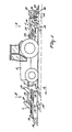
- the apparatus shown in the Figures concerns a plough consisting of two parts 1 and 2 cooperating during operation, which parts by means of a three-point hitch attachment are attached to the front side and rear side, respectively, of a tractor 3.
- the front part 1 of the plough comprises an at least substantially horizontal frame beam 4 extending transverse to the direction of travel A and being provided at each of its ends with an arm 5, the longitudinal centre line of which includes an angle of ⁇ 50° with the longitudinal centre line of said frame beam.
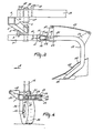
- the arms 5 are situated at the same side of the frame beam 4 and extend from the frame beam 4 rearwardly and slightly downwardly (Figure 3).
- each of the arms 5 By means of an upwardly, preferably vertically, extending swivel shaft 6 there is arranged at the ends of each of the arms 5 an at least substantially horizontal frame beam 7 extending substantially in the direction of travel.
- a swivel shaft 6 is situated near an end of the frame beam 7.
- a pin 8 which can be passed through a lip 9 on the arm 5 and one of two holes 10 provided in the frame beam 7
- each frame beam 7 can be secured in two positions distorted over 180° relative to the arm for bringing the plough in working positions, which will be discussed in more detail hereafter.
- the frame beams 7 are arranged mirror image-wise relative to each other in respect of a vertical plane of symmetry B-B through the centre of the frame beam 4 and the tractor 3.
- the frame beams 7 diverge forwardly whereby their longitudinal centre lines include an angle of ⁇ 30° with the plane of symmetry.
- each of the frame beams 7 is provided with a lip 11 which, in the position of the beams indicated by uninterrupted lines, is directed outwardly.
- Each of the lips 11 constitutes a bearing for a pivot pin 12 which is situated at the end of a carrier 13.
- Each carrier 13 is arranged rotatably about its longitudinal axis between the lips 11 and extends at least substantially parallel to the frame beam 7.
- each carrier 13 is provided with plate-shaped supports 14 which are located above each other and, seen from above, are substantially triangular in shape.
- an arm 16 which is constituted by two strips located above each other and extending in the direction of the carrier 13 and obliquely rearwardly, as is apparent from Figure 2.
- an arm 19 adapted for pivotal movement.
- an arm 19 assumes the position indicated in Figure 3. In this position, the arm 19 extends over a part at least substantially horizontally to the rear and at least substantially in the direction of travel A. The said part of the arm 19 merges via a curve into a straightly downwardly directed part which again merges into an obliquely forwardly and downwardly directed part that carries a plough body 20.
- Each plough body 20 is provided with a share 21 and a mouldboard 22 connected thereto.
- a leaf spring 23 At the top side of the lugs 17 there is arranged pivotably an end of a leaf spring 23, the other end of which is arranged pivotably at the rear side of the rearwardly extending part of the arm 19 by means of a lug 24.
- the spring 23 With its broadest side, the spring 23 is located at least substantially parallel to the top side of the arm 19 ( Figure 3) and keeps the arm against an abutment 25 which is situated at the bottom side of the lugs 17.
- a pin 26 which extends at least substantially parallel to the shaft 15, between the supports 14 there is arranged pivotably a support portion 27. In the support portion 7 an end of a screw spindle 28 is supported.
- the screw spindle is adapted to cooperate with a sleeve 29, which is arranged pivotably between the strips of the arm 16 ( Figure 2). Between the support portion 27 and the sleeve 29 there is provided around the screw spindle 28 a pressure spring 30, all this in such a manner that by turning the screw spindle the tension in the spring can be controlled along with a pivotal movement of the strip-shaped arm 16.
- each carrier 13 is provided with a lug 31, to which is arranged pivotably by means of a pin an end of an adjusting cylinder 32 which, by means of a pin, with its other end is arranged pivotably between lugs 33 attached to the frame beam 7.
- each frame beam 7 is provided with an obliquely downwardly and forwardly directed arm 34, which at its bottom end comprises an at least substantially horizontally extending transverse shaft 35, around which a ground wheel 36 is freely rotatable (Figure 4).
- the frame beam 4 is provided at the rear side with a support 37.
- the support 37 is provided with an at least substantially vertical swivel shaft 38.
- About the swivel shaft 38 is pivotable the end of a frame beam 39 which extends parallel to the direction of travel A and of which the longitudinal centre line is situated in the plane of symmetry B-B.
- Part 2 of the plough which during operation is situated behind the tractor, comprises an at least substantially horizontal frame beam 42 extending transverse to the direction of travel A and being provided at its ends with vertically extending beams 43 (Figure 7).
- the beams 43 are connected with each other by means of a beam 44 extending parallel to the frame beam 42.
- a shaft 45 On either side of the centre in a point which is situated ⁇ 1/4 of the length of the beam from its ends, there is bearing-supported in the beam 42 a shaft 45 extending in the direction of travel A ( Figure 5).
- each shaft 45 is provided with two spaced, upwardly extending lips 46. Between each pair of lips 46 there is arranged by means of a pivot shaft 47 extending transverse to the direction of travel A an arm 19 for a plough body 20 ( Figure 7).
- each arm 19 is provided with a leaf spring 23 which counteracts a pivotal movement of the arm about the shaft 47 and attempts to keep this arm against an abutment.
- each lug 50 is pivotably connected with a rod 52 extending transverse to the direction of travel A ( Figure 7).
- the adjusting cylinder 53 is fitted near an end of the frame beam 42.
- a horizontal lip 54 extending rearwardly.
- a vertical shaft 55 is pivotable.
- each sleeve 56 rigidly connected to the shaft.
- a box-like carrier beam 57 which extends rearwardly.
- a support Between the bottom side of each carrier beam 57 and the sleeve 56 there is present a support.
- shafts 58 situated parallel to the shafts 55, the ends of the carrier beams 57 are arranged pivotably between lips 59 located at the front side of a frame beam 60 extending transverse to the direction of travel A.
- the frame beam 60 connects the ends of vertically downwardly extending beams 61 ( Figure 6).
- the beams 61 are arranged at the top side of a box-like frame portion 62 which constitutes part of an implement 63, which is constructed as a rotary harrow and by means of which the soil, cultivated by the afore-mentioned plough bodies 20, can be crumbled.
- the upwardly extending beams 61 are fitted at the ends and the rear side of the box-like frame portion 62.
- the upwardly, preferably vertically, extending shafts of five soil working members 64 are bearing-supported side by side equally interspaced at preferably 25 centimeters.
- Each of the soil working members 64 comprises an at least substantially horizontal carrier fitted onto the end of its shaft projecting below the frame portion, which carrier, near its ends, is provided with downwardly extending soil working members in the form of tines.
- pivot points 65 there are arranged to each of the upright beams 61 arms 66 and 67.
- the lower arm 67 is shorter than the upper arm 66. With their other ends, the arms 66 and 67 are connected pivotably to an upwardly extending support 68.
- the support 68 which is preferably U-shaped, is so arranged that the legs of the U are directed outwardly.
- the other side of each support 68 is attached near the centre to the top side of a plate 69.
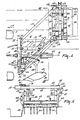
- the top side of the plate 69 which extends at least substantiallqpparallel to the direction of travel A, is bent over slightly outwardly and via a bend merges into a downwardly extending portion which in the topmost position of the arms (66 and 67) is situated at least substantially vertically (see Figure 6).
- the top side of the plate 61 extends at least substantially vertically, while the part of the plate situated thereunder assumes a position which is directed slightly obliquely downwardly and outwardly, all this in such a manner that, as has been indicated in Figure 6 for the left-hand plate 69, during operation the plate can move along the vertical side of the furrow.
- a straight-toothed gearwheel Inside the box-like frame portion 62, on each of the shafts of a soil working member 64 there is fitted a straight-toothed gearwheel, all this in such a manner that the gearwheels of adjacent soil working members are in driving connection with each other.
- leftmost shaft of a soil working member 64 is extended upwardly, which shaft is passed through a tube 70 situated on the top side of the frame portion 62.
- the tube 70 is arranged at the bottom side of a gear box 71.
- the gear box 71 is pivotably connected with a carrier beam 57 and rotatable about an axis which coincides with the longitudinal centre line of the shaft arranged inside said tube.
- the shaft arranged in the tube 70-of which shaft the longitudinal centre line is aligned with the longitudinal centre lines of the shafts 58 ( Figure 5)-is in connection with a shaft 73 via a conical gear transmission.
- the shaft 73 is connected with a shaft 74 provided with universal couplings.
- the other end of the shaft 74 is connected with a shaft 75 in a gear box 76 which, in the same manner as the gear box 71, is pivotably connected with the front end of a carrier beam 57 by means of an arm 72.
- the arms 72 constitute part of a parallelogram construction.
- the gear box 76 is pivotable about the longitudinal centre line of a shaft 77 which, via a conical gear transmission in a gear box 78, is in connection with a shaft 79.
- the gear box 78 is attached to the frame beam 42.
- the shaft 79 is bearing-supported in a gear case 80, inside which on the shaft there is arranged a sprocket wheel 81, around which is thrown a chain which is also thrown around a sprocket wheel 82.
- the sprocket wheel 82 is fitted on a shaft 83 extending in the direction of travel A and being connectable with the power take-off shaft of a tractor by means of an intermediate shaft.
- the box-like frame portion 62 is provided at its front side with pins 84 extending transverse to the direction of travel A, around which pins are pivotable rearwardly extending arms 85, which near the rear side of the box-like frame portion by means of an adjusting device can be brought and fixed in several positions in a manner not shown.
- a roller 86 which in this embodiment is constructed as a packer roller.
- the frame beam 60 is on either side of the centre provided with a lip 87, which by means of a pin 88 is arranged pivotably between pairs of lips 89.
- the lips 89 are situated at the front side of a hopper 90, extending transverse to the direction of travel A, of an apparatus 91 for bringing material, e.g. sowing seed, onto or into the soil.
- the bottom side of the hopper 90 rests on a support 92 which is situated near the centre of the lowermost frame beam 42.
- the hopper 90 is provided with a mechanism for discharging the material via tubes 93 connected to the bottom side of the hopper, which tubes, as is apparent from Figure 1, extend at least to the ground level.
- the plough bodies 20 seen in the direction of travel to the left of the plane of symmetry B-B through the longitudinal centre of the tractor, are situated in the position indicated in Figures 1, 2 and 5, whereby the working depth is determined by the ground wheels 36 and 49 which-although not shown--can be arranged adjustably in height.
- the plough bodies situated at the other side of the plane of symmetry B-B are brought into a position as indicated in the Figures 1 and 2 by means of the hydraulic adjusting cylinders 32 and 53.
- the left frontmost plough bodies 20 are pivoted about the longitudinal centre line of the carrier 13 in the indicated position and the left plough body 20 of the rearmost part 2 about the shaft 45 in the indicated position.
- the soil cultivating machine in the form of a rotary harrow which belongs to the plough and sees to a further crumbling of the soil, assumes the position as indicated in Figure 5, whereby the adjacent furrow slices, laterally displaced and turned by the two frontmost plough bodies and the rearmost plough body, are crumbled by means of the soil working elements of the soil working members 64 and are compressed by means of the packer roller, so that immediately material can be brought into the thus treated soil from the hopper 90 of the apparatus 91 for bringing material, e.g. sowing seed, onto or into the soil.
- material e.g. sowing seed
- the drive for the soil working members 64 which counter-rotate during operation, is effected via the above-described drive from the power take-off shaft of the tractor.
- the plough according to the invention in one operation both a primary and a secondary soil cultivation, all this in such a manner that immediately hereafter the soil can be sown.
- the left plane 69 fitted to the frame portion 62 in its position as indicated, sees to it that no soil is stowed into the open furrow ( Figure 6).
- the other plate 69 passes over the already cultivated soil and, because the length of the lowermost arm 67 is less than that of the topmost arm 66, assumes a position as is indicated in Figure 6, whereby the plate stands practically vertical and can co-operate with the outermost soil working member 64 for a further crumbling and distribution of the soil, so that a proper link-up is obtained with the adjacent, already cultivated strip of soil.
- the tractor At the end of the field, it is possible from the tractor to bring by means of the hydraulic adjusting cylinder 32 the frontmost two plough bodies 20 by pivoting about the longitudinal axis of the carrier 13 into the inoperative position and the other pair of frontmost plough bodies 20 into their operative position.
- a change from the operative position to the inoperative position for the plough bodies 20 of the rearmost part 2 of the plough can be effected from the tractor by means of the adjusting cylinder 53.
- the carrier beams 57 which constitute a parallelogram construction and carry the whole of crumbling device or rotary harrow 63 and the apparatus 91, can be brought into the position indicated in Figure 5 by dash lines by means of the hydraulic adjusting cylinder 95 from the tractor.
- the plough bodies at the front side can be adapted to the movements of the tractor-in which connection they are adapted to deviate against the action of the springs 30 about the shafts 15 by means of the screw spindle 28-it is possible to obtain at wish an adaption of the position of the plough bodies and of the spring tension.
- the pivotably arranged arm 19 carrying a plough body 20 and the leaf springs 23 it is possible, if during operation a plough body hits upon an obstacle, for said plough body together with the arm to pivot upwardly about the shaft 18 against the action of the leaf spring 23 in order to discharge the obstacle or to move thereover, after which the plough body immediately returns into its desired operative position.
Landscapes
- Life Sciences & Earth Sciences (AREA)
- Engineering & Computer Science (AREA)
- Mechanical Engineering (AREA)
- Soil Sciences (AREA)
- Environmental Sciences (AREA)
- Zoology (AREA)
- Soil Working Implements (AREA)
Claims (14)
Applications Claiming Priority (4)
| Application Number | Priority Date | Filing Date | Title |
|---|---|---|---|
| NL8501065A NL8501065A (nl) | 1985-04-11 | 1985-04-11 | Ploeg. |
| NL8501066A NL8501066A (nl) | 1985-04-11 | 1985-04-11 | Ploeg. |
| NL8501065 | 1985-04-11 | ||
| NL8501066 | 1985-04-11 |
Publications (2)
| Publication Number | Publication Date |
|---|---|
| EP0199406A1 EP0199406A1 (de) | 1986-10-29 |
| EP0199406B1 true EP0199406B1 (de) | 1989-10-18 |
Family
ID=26646039
Family Applications (1)
| Application Number | Title | Priority Date | Filing Date |
|---|---|---|---|
| EP19860200598 Expired EP0199406B1 (de) | 1985-04-11 | 1986-04-09 | Pflug |
Country Status (2)
| Country | Link |
|---|---|
| EP (1) | EP0199406B1 (de) |
| DE (1) | DE3666319D1 (de) |
Cited By (1)
| Publication number | Priority date | Publication date | Assignee | Title |
|---|---|---|---|---|
| EP4677978A1 (de) * | 2024-07-10 | 2026-01-14 | ROTER ITALIA Srl | Landwirtschaftliche maschine |
Families Citing this family (11)
| Publication number | Priority date | Publication date | Assignee | Title |
|---|---|---|---|---|
| NL8800800A (nl) * | 1988-03-30 | 1989-10-16 | Lely Nv C Van Der | Combinatie van een trekker met ten minste een grondbewerking-zaaieenheid. |
| NL8902832A (nl) * | 1989-11-16 | 1991-06-17 | Lely Nv C Van Der | Landbouwmachine. |
| GB9114636D0 (en) * | 1991-07-06 | 1991-08-21 | Samuel Harold R | Reseeding pasture |
| NL9101330A (nl) * | 1991-08-02 | 1993-03-01 | Lely Nv C Van Der | Grondbewerkingsmachine. |
| FR2696614B1 (fr) * | 1992-10-09 | 1994-12-09 | Gregoire Besson Ets | Machine de préparation de sols et de semis. |
| GB2447403A (en) * | 2007-03-12 | 2008-09-17 | Jim Tarry | A multi unit soil cultivation device incorporating a swivel based plough |
| ES2399868B1 (es) * | 2011-02-22 | 2013-11-22 | Julio SANTAMARIA MARTINEZ | Arado hidraulico accionado por empuje de vehiculo tractor |
| NO336586B1 (no) | 2013-10-18 | 2015-09-28 | Kverneland Group Operations Norway As | Festearrangement for bladfjørsammenstilling |
| DE202017107892U1 (de) * | 2017-12-22 | 2018-01-12 | Konrad Hendlmeier | Grubberscharmodul für eine Bodenbearbeitungsvorrichtung |
| CN110249798A (zh) * | 2019-07-30 | 2019-09-20 | 吉林大学 | 一种秸秆揉丝密化还田机 |
| CN116195391B (zh) * | 2023-02-22 | 2023-10-20 | 黑龙江省农业机械工程科学研究院 | 一种组合式犁具、犁地机及其犁地培肥方法 |
Family Cites Families (10)
| Publication number | Priority date | Publication date | Assignee | Title |
|---|---|---|---|---|
| CH333812A (fr) * | 1955-03-09 | 1958-11-15 | Bobard Emile | Train arrière moteur et directeur d'un tracteur équipé d'instruments aratoires |
| FR1242378A (fr) * | 1959-08-21 | 1960-09-30 | Bineuse à bielle brisée | |
| FR1257784A (fr) * | 1960-02-25 | 1961-04-07 | Perfectionnements aux dispositifs de fixation des fraises et instruments de culture analogues sur les tracteurs agricoles | |
| US3224392A (en) * | 1964-09-08 | 1965-12-21 | Mellen William Fisk | Soil tillage apparatus |
| FR1521767A (fr) * | 1966-05-02 | 1968-04-19 | Przemyslowy Inst Masz Rolniczy | Dispositif tracté pour cultiver et semer |
| FR1597138A (de) * | 1968-12-24 | 1970-06-22 | ||
| FR2180520B3 (de) * | 1972-04-19 | 1975-06-20 | Aranzabal & Cia Sa | |
| US4141419A (en) * | 1977-03-21 | 1979-02-27 | Iowa State Univ. Research Foundation, Inc. | Method and apparatus for controlling the approach angle of a plow unit in response to speed variations |
| DE3136869C2 (de) * | 1981-09-17 | 1986-09-18 | Rabewerk Heinrich Clausing, 4515 Bad Essen | Frontpflug |
| FR2549339B1 (fr) * | 1983-07-19 | 1985-10-25 | Dehondt Jean Claude | Charrue de type " poussee " et son attelage permettant le labour, la preparation du lit de semence et le semis d'un champ en un seul passage et avec un seul conducteur |
-
1986
- 1986-04-09 EP EP19860200598 patent/EP0199406B1/de not_active Expired
- 1986-04-09 DE DE8686200598T patent/DE3666319D1/de not_active Expired
Cited By (1)
| Publication number | Priority date | Publication date | Assignee | Title |
|---|---|---|---|---|
| EP4677978A1 (de) * | 2024-07-10 | 2026-01-14 | ROTER ITALIA Srl | Landwirtschaftliche maschine |
Also Published As
| Publication number | Publication date |
|---|---|
| DE3666319D1 (en) | 1989-11-23 |
| EP0199406A1 (de) | 1986-10-29 |
Similar Documents
| Publication | Publication Date | Title |
|---|---|---|
| US4088083A (en) | Rotary harrow and attachments | |
| US4036154A (en) | Soil cultivating implements | |
| EP0199406B1 (de) | Pflug | |
| CZ115498A3 (cs) | Integrované zařízení pro kultivaci půdy | |
| EP0198563B1 (de) | Landwirtschaftliche Maschine | |
| EP0271119B1 (de) | Bodenbearbeitungsmaschine | |
| US5318134A (en) | Irrigation furrow and raised seed bed forming machine | |
| US3335681A (en) | Agricultural tillage unit | |
| US4058068A (en) | Soil cultivating and sowing implement | |
| EP0171861B1 (de) | Pflug | |
| EP0337534B1 (de) | Bodenbearbeitungsmaschine | |
| EP0422721A1 (de) | Landwirtschaftliches Gerät, insbesondere Bodenbearbeitungsmaschine | |
| EP0436975B1 (de) | Bodenbearbeitungsmaschine | |
| EP0181039B1 (de) | Pflug | |
| EP0620962B1 (de) | Bodenbearbeitungsmaschine | |
| EP0305601B1 (de) | Gerät zur Bodenbearbeitung | |
| EP0288125B2 (de) | Bodenbearbeitungsmaschine | |
| EP0305600B1 (de) | Gerät zur Bodenbearbeitung | |
| EP0283078B1 (de) | Bodenbearbeitungsmaschine | |
| EP0254350B1 (de) | Bodenbearbeitungsmaschine | |
| EP0201135B1 (de) | Bodenbearbeitungsmaschine | |
| EP0432815A2 (de) | Landwirtschaftliche Maschine | |
| NL9400177A (nl) | Grondbewerkingsmachine. | |
| NL8501065A (nl) | Ploeg. | |
| EP0429138A1 (de) | Bodenbearbeitungsmaschine |
Legal Events
| Date | Code | Title | Description |
|---|---|---|---|
| PUAI | Public reference made under article 153(3) epc to a published international application that has entered the european phase |
Free format text: ORIGINAL CODE: 0009012 |
|
| AK | Designated contracting states |
Kind code of ref document: A1 Designated state(s): DE FR GB NL |
|
| 17P | Request for examination filed |
Effective date: 19870408 |
|
| 17Q | First examination report despatched |
Effective date: 19880321 |
|
| GRAA | (expected) grant |
Free format text: ORIGINAL CODE: 0009210 |
|
| AK | Designated contracting states |
Kind code of ref document: B1 Designated state(s): DE FR GB NL |
|
| REF | Corresponds to: |
Ref document number: 3666319 Country of ref document: DE Date of ref document: 19891123 |
|
| ET | Fr: translation filed | ||
| PLBE | No opposition filed within time limit |
Free format text: ORIGINAL CODE: 0009261 |
|
| PLBI | Opposition filed |
Free format text: ORIGINAL CODE: 0009260 |
|
| PLAB | Opposition data, opponent's data or that of the opponent's representative modified |
Free format text: ORIGINAL CODE: 0009299OPPO |
|
| 26 | Opposition filed |
Opponent name: LIBERTY Effective date: 19900719 |
|
| 26N | No opposition filed | ||
| R26 | Opposition filed (corrected) |
Opponent name: LIBERTY Effective date: 19900718 |
|
| PLAA | Information modified related to event that no opposition was filed |
Free format text: ORIGINAL CODE: 0009299DELT |
|
| NLR1 | Nl: opposition has been filed with the epo |
Opponent name: LIBERTY. |
|
| NLXE | Nl: other communications concerning ep-patents (part 3 heading xe) |
Free format text: IN PAT.BUL.22/90,FILING DATE OF THE OPPOSITION CORR.:900718 |
|
| PLBN | Opposition rejected |
Free format text: ORIGINAL CODE: 0009273 |
|
| STAA | Information on the status of an ep patent application or granted ep patent |
Free format text: STATUS: OPPOSITION REJECTED |
|
| 27O | Opposition rejected |
Effective date: 19920613 |
|
| NLR2 | Nl: decision of opposition | ||
| PGFP | Annual fee paid to national office [announced via postgrant information from national office to epo] |
Ref country code: DE Payment date: 19960524 Year of fee payment: 11 |
|
| PG25 | Lapsed in a contracting state [announced via postgrant information from national office to epo] |
Ref country code: DE Free format text: LAPSE BECAUSE OF NON-PAYMENT OF DUE FEES Effective date: 19980101 |
|
| REG | Reference to a national code |
Ref country code: GB Ref legal event code: IF02 |
|
| PGFP | Annual fee paid to national office [announced via postgrant information from national office to epo] |
Ref country code: FR Payment date: 20020319 Year of fee payment: 17 |
|
| PGFP | Annual fee paid to national office [announced via postgrant information from national office to epo] |
Ref country code: NL Payment date: 20020321 Year of fee payment: 17 |
|
| PGFP | Annual fee paid to national office [announced via postgrant information from national office to epo] |
Ref country code: GB Payment date: 20020403 Year of fee payment: 17 |
|
| PG25 | Lapsed in a contracting state [announced via postgrant information from national office to epo] |
Ref country code: GB Free format text: LAPSE BECAUSE OF NON-PAYMENT OF DUE FEES Effective date: 20030409 |
|
| PG25 | Lapsed in a contracting state [announced via postgrant information from national office to epo] |
Ref country code: NL Free format text: LAPSE BECAUSE OF NON-PAYMENT OF DUE FEES Effective date: 20031101 |
|
| GBPC | Gb: european patent ceased through non-payment of renewal fee |
Effective date: 20030409 |
|
| NLV4 | Nl: lapsed or anulled due to non-payment of the annual fee |
Effective date: 20031101 |
|
| PG25 | Lapsed in a contracting state [announced via postgrant information from national office to epo] |
Ref country code: FR Free format text: LAPSE BECAUSE OF NON-PAYMENT OF DUE FEES Effective date: 20031231 |
|
| REG | Reference to a national code |
Ref country code: FR Ref legal event code: ST |