EP0199566A2 - Film chauffant - Google Patents
Film chauffant Download PDFInfo
- Publication number
- EP0199566A2 EP0199566A2 EP86302955A EP86302955A EP0199566A2 EP 0199566 A2 EP0199566 A2 EP 0199566A2 EP 86302955 A EP86302955 A EP 86302955A EP 86302955 A EP86302955 A EP 86302955A EP 0199566 A2 EP0199566 A2 EP 0199566A2
- Authority
- EP
- European Patent Office
- Prior art keywords
- heater
- elements
- connection elements
- connection
- support
- Prior art date
- Legal status (The legal status is an assumption and is not a legal conclusion. Google has not performed a legal analysis and makes no representation as to the accuracy of the status listed.)
- Withdrawn
Links
Images


Classifications
-
- F—MECHANICAL ENGINEERING; LIGHTING; HEATING; WEAPONS; BLASTING
- F24—HEATING; RANGES; VENTILATING
- F24D—DOMESTIC- OR SPACE-HEATING SYSTEMS, e.g. CENTRAL HEATING SYSTEMS; DOMESTIC HOT-WATER SUPPLY SYSTEMS; ELEMENTS OR COMPONENTS THEREFOR
- F24D13/00—Electric heating systems
- F24D13/02—Electric heating systems solely using resistance heating, e.g. underfloor heating
-
- Y—GENERAL TAGGING OF NEW TECHNOLOGICAL DEVELOPMENTS; GENERAL TAGGING OF CROSS-SECTIONAL TECHNOLOGIES SPANNING OVER SEVERAL SECTIONS OF THE IPC; TECHNICAL SUBJECTS COVERED BY FORMER USPC CROSS-REFERENCE ART COLLECTIONS [XRACs] AND DIGESTS
- Y02—TECHNOLOGIES OR APPLICATIONS FOR MITIGATION OR ADAPTATION AGAINST CLIMATE CHANGE
- Y02B—CLIMATE CHANGE MITIGATION TECHNOLOGIES RELATED TO BUILDINGS, e.g. HOUSING, HOUSE APPLIANCES OR RELATED END-USER APPLICATIONS
- Y02B30/00—Energy efficient heating, ventilation or air conditioning [HVAC]
Definitions
- the present invention relates to wall, floor and ceiling heaters.
- a further disadvantage associated with many of the systems of the prior art is that the heater elements have to be electrically interconnected on site, which further lengthens the installation time, and increases the expense, and the chances of error on installation.
- the present invention provides a wall, floor or ceiling heater which can be fitted in a room during or after construction, and which obviates problems associated with prior art heaters.
- a wall, floor or ceiling heater having the form of a sheet and comprising a plurality of elongate self-regulating electrical heater elements, each of which is connected to at least two connection elements, and a support to hold the heater elements and the connection elements in a substantially fixed spatial relationship in the plane of the sheet.
- the self-regulating properties of the heater elements of the heater confer several advantages. Firstly, the heat output of the heater is variable according to requirements in any part of a room; thus, more heat can be given out in the colder parts of a room such as in the vicinity of windows, and less heat can be given out in the warmer parts of a room. Secondly, the heater is safer and more reliable in use than comparable constant wattage heaters since the heater elements are unable to overheat. Thus the likelihood of the elements burning out is significantly reduced. Furthermore, furniture, wall hangings and other insulating fittings can be placed on or against the heater without risk of overheating, which allows more flexibility in the laying out of the furniture etc.
- the heater being in sheet form makes installation and servicing more convenient.
- the present heater can be installed after construction of a room, for example as a carpet or wall-covering, with a layer of an appropriate facing material where necessary.
- the facing material may serve to protect the heater for example from mechanical abuse or from fluids or other chemical agents, or it may serve an aesthetic function, for example to enhance the visual appearance of the heater.
- the self-regulating heater elements comprise a material which exhibits PTC behaviour, particularly a PTC conductive polymer which comprises a polymeric component and, dispersed therein, a particulate conductive filler, particularly carbon black.
- a PTC conductive polymer which comprises a polymeric component and, dispersed therein, a particulate conductive filler, particularly carbon black.
- Known self-regulating heater elements are suitable for this purpose, including in particular conventional conductive polymer strip heaters which comprise two conductors embedded in a melt-extruded strip of a PTC conductive polymer.
- sheet heaters disclosed in European Patent Application No. 85300415.8 and in U.S. Serial Nos. 650,918, 650,919, and 650,920.
- PTC conductive polymers and electrical devices including self-regulating heaters, comprising PTC conductive po'ly-.
- the elongate heater elements used in the present heater will comprise a strip or layer, preferably a melt-extruded strip or layer, of a conductive polymer which exhibits PTC behaviour, having embedded therein, or secured, eg. deposited, thereon, two or more electrodes, for example interdigitated electrodes printed on the surface of a conductive polymer layer or two elongate parallel electrodes which extend generally parallel along the element.
- a strip heaters which have a generally flattened, tape-like cross-section. The heating elements are preferably laid flat along their entire length.
- heaters which comprise substantially parallel heater elements with connection elements running perpendicular thereto, can be cut along any line substantially parallel to the heater elements.
- Heaters in which the heater elements are connected to the connection elements at one end of each heater element can also be cut to fit along a line substantially perpendicular to the heater elements. In this case, the ends of the heater elements that are exposed by cutting should be sealed for safety, and to prevent the formation of a short circuit between the exposed electrodes.
- the heater can be manufactured and supplied in standard widths, such as 0.4 m or less, 0.8 m, 1.0 m, 1.5 m, 2.0 m and more.
- the configuration of the heater elements of the heater will depend on the application to which the heater is to be put. For many applications a generally square or rectangular configuration will be appropriate. In such a configuration, the heater elements preferably extend generally parallel in a first direction.
- the connection elements preferably extend perpendicular to that direction.
- Other configurations are however possible; these include radial configurations in which a number of heater elements radiate from a single point, or are connected to two points. Preferably however, the heater elements are spaced apart along their entire length.
- connection elements and the heater elements are in a substantially fixed spatial relationship, and this makes easier the task of installing the heater, since it is not necessary to assemble and to interconnect the various components on site.
- the heater is flexible, at least around one axis, which advantageously allows the heater to be folded or rolled temporarily for ease of transportation.
- the heater may be flexible about an axis which is parallel to the heater elements. It will be understood that the heater elements and connection elements of a flexible heater will nevertheless be in a substantially fixed spatial relationship within the plane of the sheet when the heater is laid flat, or installed on a wall, floor or ceiling.
- the present heaters when installed, can be arranged to have a low profile and to be light in weight.
- the installed heater can be arranged to have a thickness of less than 1cm, and a weight of less than 500g/m 2 , for example 250g/m 2 .
- the low profile of the heaters can be achieved by using tape-like heater elements which have a flattened cross-section, laid flat (that is on a principle surface of the tape) along their length.
- the present heater construction is in contrast to those of the prior art, in which the heater elements are installed under several centimetres of a grout such as concrete; the low profile and light weight of the present system make it particularly suitable for use as a retrofit system, in rooms in which the use of a wall, floor or ceiling heaters had not initially been intended.
- the heater may be installed as a carpet layer, a wall covering or in a skirting board.
- connection elements may be in the form of bus bars extending along one or more edges of the heater.
- the heater may have a comb configuration, in which two bus bars are provided along one edge of the sheet, to which the two elongate electrodes of each heater element which is preferably in the form of a tape, can be connected, at the same end of each element.
- one or more bus bars may be provided along each of two opposite edges between which the heater elements are located; two electrodes in each heater element may then be connected to a respective bus bar at opposite ends of the element. This can be seen as a ladder configuration.
- a heater can be constructed in which a pair of connection elements interconnects less than all of the elements; for example, a separate pair of connection elements can be used to interconnect each adjacent pair of heater elements.
- each heater element can be connected at the same end to both of its adjacent heater elements, or it can be connected to one of its adjacent heater elements at each end.
- the support can be extruded around the connection elements so that the support itself can comprise the electrical insulation for the elements.
- the connection elements may however be pre-coated with a suitable temperature resistant insulation.
- connection elements there are many factors to be taken into account when deciding on the wiring layout. For example, in some circumstances, it may be advantageous to construct the heater with all of the connection elements extending along one edge, since the width of the heater can then be cut to fit the particular application. The cut-to- fit facility arises from the parallel circuitry of the heater elements. In other circumstances, it may be advantageous to interconnect the heater elements by means of connection elements at each end of the heater elements, since the connections can be arranged such that there are no points at which either connection elements or electrodes cross over; the heater can therefore be arranged to have a lower profile. In some circumstances, it is advantageous to arrange the connection elements such that substantially all of the heater elements are connected to one pair, since this minimises the number of ends of electrodes and connection elements to be connected.
- connection elements can be made, for example by crimping to a stripped portion of the connection element which may be an end portion or a portion between the ends of the conductor, by an insulation piercing stud on a printed circuit board, by welding or by soldering.
- Insulation of the electrical connection may be effected in any of several ways, for example by use of a heat-shrinkable tuoular or appropriately moulded part, or by use of an encapsulating gel as disclosed in GB-A-2133026 the disclosure of which is incorporated herein by reference.
- the support may be extruded around the connection elements; recesses may be provided at intervals in the support exposing short lengths of connection elements for connection to the heater elements.
- the recesses may be filled with an appropriate insulation material, for example a gel, or a hardening or curing resin, for example an epoxy or polyurethane potting compound.
- the support comprises a sheet material having a thermal conductivity of at least 50 W/mK.
- the support comprises a sheet or strip of material, the material supporting the heater elements on at least one of its principle surfaces.
- the heater elements may be sandwiched between two laminated supporting sheets of material. The laminated sheets may be fixed together, for example by an adhesive, rivets, screws etc.
- the support preferably provides mechanical protection for the heater elements.
- One of the sheets may comprise one or more strips or tapes.
- the support may comprise a layer of material, which the heater elements may be embedded in, or laid upon.
- the support may comprise rigid or resilient material, for example a foam material, rigid sheets of polyamide or polyester, fibrous sheets etc.
- a component of the support particularly in strip form, may be used as a spacer between the heater elements to ensure that the principal surfaces of the heater are substantially even and to support loads placed against the heater.
- strips of support material may be placed such that adjacent strips abut, and furthermore the abutting edges may be hinged to allow the heater to be rolled or folded.
- the hinge may be provided by an adhered film.
- the support comprises hinged strips of material, the heater elements are preferably embedded in grooves in the strips.
- connection elements may extend perpendicular to the hinge and in such circumstances it may be desirable to provide the connection elements with a kink or bend in the region of the hinge to facilitate bending of the connection element when the heater is rolled up.
- a kink or bend may be produced by appropriate in-line manufacturing techniques if the support is extruded around the connection elements.
- a sheet of a metal, or of a material having a thermal conductivity of at least 30 W/mK is incorporated into the heater to ensure that heat is dissipated more evenly over the area of the heater. Aluminium is preferred for its light weight.
- the aluminium may be incorporated as a foil, for example by adhering to the sheet on which the heater elements are mounted, or the sheet may itself comprise aluminium.
- a metal member, incorporated for heat transfer properties, may also be used as an electrical grounding layer; alternatively or in addition, a woven or braided layer, or a layer of another electrically conductive material may be used for this purpose.
- a resilient material may be incorporated into the heater construction, either across the whole heater, or to protect only selected areas, such as the heater elements.
- a layer of material may be incorporated into the support for for aesthetic reasons, for example to provide decoration for the room to to be heated.
- the heater may include, or be adapted to interface with, control equipment such as thermostats and timer equipment.
- each heater comprises connection elements 2 and heater elements 4, the heater elements comprising electrodes 6 which extend along the length of the elements.
- the elements of the heater shown in Figure 1a are arranged in a comb configuration, in which a pair of connection elements extends along an edge of the heater, and in which respective electrodes 6 of each heater element are connected to the connection elements at one end of the heater elements.
- the heater may be cut to length and width to suit the particular application.
- connection elements are again arranged in a comb configuration. However, individual pairs of connection elements are used to connect each adjacent pair of heater elements, the connection between heater element and connection elements being made by crimping.
- connection element extends along each edge 8,10, with the heater elements between them, the electrodes of each heater element being connected to respective connection elements at opposite ends of the heater elements.
- This configuration can be arranged to be of lower profile than those of Figures la and b, since it is not necessary for electrodes and/or connection elements to cross over at the point of connection.
- a heater having a similarly low profile can be achieved using the configuration shown in Figure 1d, in which a pair of connection elements is used to interconnect each adjacent pair of heater elements.
- connection elements 2 are doubly insulated: the outer insulation 20 is removed in the joint region, and the inner insulation 22 is removed from the elements at spaced apart regions.
- a loop 28 is formed in each stripped connection element, to which respective electrodes 30,32 of the heater element 34 are connected by crimps 36.
- An insulator place 38 suitably notched to fit over the connection elements, prevents the stripped portions of connection elements and/or the electrodes of the heater element from short circuiting.
- the joint is enclosed in an insulating housing 40, shown in dotted outline which may te a heat-shrinkable moulded part, or a gel-coated part.
- Figure 3 shows a cross section through a floor heater.
- the configuration of the heater elements is as shown in Figure la, the cross-section being taken along the line A-A.
- the heater comprises heater elements 4 mounted on an aluminium sheet 30 to which an aluminium cover sheet 32 has been laminated, so as to sandwich the heater elements between the sheets.
- Rigid spacers 34 are provided between the heater elements such that the upper surface of the heater is substantially even.
- the lower surface of the heater is provided with a layer of resilient foam 36.
- the support comprises strips 40 of a rigid polymeric material, such as a polyamide.
- the strips are hinged by means of a film 42 which is adhered to the surface of the strips.
- the film may comprise polymeric or metallic material.
- the heater elements 44 are laid in grooves in the strips of the support and held there by means of a layer of alumin ium foil 46 which overlies the grooves.
- FIG. 5 shows one element of a co-extruded heater according to the invention.
- the heater comprises a heater element 50 with electrodes 51,52 soldered to connection elements 53,54 respectively. Elements 53,54 are embedded in the heater support 55, by extrusion of the support around the elements.
- a sheet metal cover plate 56 is provided over the heater element 50 which lies in a groove 57 in the support 55 and acts as a mechanical protection for the heater element.
- a recess 58 is provided in the extruded support 55 to permit connection of the electrodes 51,52 to the connection elements 53,54. Subsequent to the soldered connection the recess 58 is filled with an epoxy resin (not shown).
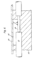
- Figure 6 shows in detail the connection of the electrode 51 to the connection element 53.
- a short section 59 of the insulated connection element 53 is stripped in order to allow a soldered connection to the electrode 51 which has been similarly prepared.
- the recess 58 is filled with epoxy resin and the assembly covered by the sheet metal cover plate 56.
- Figures 7a and 7b show details of the hinge produced by extrusion of the support around the connection elements.
- a thinned region 60 is left in the support and the connection elements 61 are deformed so as to produce a kink 62 at the hinged region.
- the thinned region 60 is deformed to permit the bending movement and the kink 62 is straightened out so that the assembly can be rolled up without placing undesirable tensile stresses on the connection elements or the support material.
Landscapes
- Engineering & Computer Science (AREA)
- Physics & Mathematics (AREA)
- Thermal Sciences (AREA)
- Chemical & Material Sciences (AREA)
- Combustion & Propulsion (AREA)
- Mechanical Engineering (AREA)
- General Engineering & Computer Science (AREA)
- Resistance Heating (AREA)
- Central Heating Systems (AREA)
- Surface Heating Bodies (AREA)
- Yarns And Mechanical Finishing Of Yarns Or Ropes (AREA)
- Air-Conditioning For Vehicles (AREA)
Applications Claiming Priority (6)
| Application Number | Priority Date | Filing Date | Title |
|---|---|---|---|
| GB858510058A GB8510058D0 (en) | 1985-04-19 | 1985-04-19 | Sheet heater |
| GB8510058 | 1985-04-19 | ||
| GB858524188A GB8524188D0 (en) | 1985-10-01 | 1985-10-01 | Sheet heater |
| GB8524188 | 1985-10-01 | ||
| GB8601982 | 1986-01-28 | ||
| GB868601982A GB8601982D0 (en) | 1986-01-28 | 1986-01-28 | Sheet heater |
Publications (2)
| Publication Number | Publication Date |
|---|---|
| EP0199566A2 true EP0199566A2 (fr) | 1986-10-29 |
| EP0199566A3 EP0199566A3 (fr) | 1987-08-26 |
Family
ID=27262654
Family Applications (1)
| Application Number | Title | Priority Date | Filing Date |
|---|---|---|---|
| EP86302955A Withdrawn EP0199566A3 (fr) | 1985-04-19 | 1986-04-18 | Film chauffant |
Country Status (6)
| Country | Link |
|---|---|
| US (1) | US4733057A (fr) |
| EP (1) | EP0199566A3 (fr) |
| CA (1) | CA1267675A (fr) |
| DK (1) | DK180486A (fr) |
| FI (1) | FI861646L (fr) |
| NO (1) | NO861531L (fr) |
Cited By (8)
| Publication number | Priority date | Publication date | Assignee | Title |
|---|---|---|---|---|
| DE3908141A1 (de) * | 1989-03-13 | 1990-09-20 | Grohe Kg Hans | Beheizbarer handtuchhalter |
| DE19700071A1 (de) * | 1997-01-03 | 1998-07-09 | Wolfgang Schaefer | Fußbodendrallauslaß mit regelbarer elektrischer Nachheiz-Einrichtung |
| US6621983B2 (en) | 1998-02-11 | 2003-09-16 | Tyco Thermal Controls Nordic Aktiebolag | Floor heating device with self-regulating cable |
| ITTV20090213A1 (it) * | 2009-11-02 | 2011-05-03 | Fenix Italia Srl | Apparecchiatura riscaldante a secco in materiale composito acrilico e procedimento di realizzazione di detta apparecchiatura riscaldante a secco, con rivestimento estetico sagomato di supporto d'una resistenza elettrica |
| WO2013007969A3 (fr) * | 2011-07-12 | 2013-08-15 | Uniwarm Limited | Réchauffeurs de fluides |
| WO2014015883A1 (fr) * | 2012-07-24 | 2014-01-30 | Al Bernstein | Élément de corps de radiateur à plusieurs zones de chauffage |
| CN103673043A (zh) * | 2012-08-30 | 2014-03-26 | 昆山开思拓节能技术有限公司 | 一种自控温地暖装置 |
| EP2933577B1 (fr) | 2014-04-14 | 2017-12-06 | Mahle Behr France Rouffach S.A.S | Dispositif de chauffage électrique |
Families Citing this family (74)
| Publication number | Priority date | Publication date | Assignee | Title |
|---|---|---|---|---|
| US4892452A (en) * | 1987-11-24 | 1990-01-09 | Gmx Parking Systems | Parking apparatus |
| JPH0732084B2 (ja) * | 1989-03-29 | 1995-04-10 | 株式会社村田製作所 | 有機正特性サーミスタ |
| JP2626041B2 (ja) * | 1989-04-06 | 1997-07-02 | 株式会社村田製作所 | 有機正特性サーミスタ |
| US4957012A (en) * | 1989-06-16 | 1990-09-18 | The United States Of America As Represented By The Administrator Of The National Aeronautics And Space Administration | Predictive aging of polymers |
| US4972067A (en) * | 1989-06-21 | 1990-11-20 | Process Technology Inc. | PTC heater assembly and a method of manufacturing the heater assembly |
| US4922084A (en) * | 1989-08-28 | 1990-05-01 | Gerhard Hutter | Uni-directional heating apparatus |
| US5582805A (en) * | 1992-12-21 | 1996-12-10 | Toyota Jidosha Kabushiki Kaisha | Electrically heated catalytic apparatus |
| FR2748166B1 (fr) * | 1996-04-26 | 1998-06-05 | Gec Alsthom T & D Sa | Limiteur de courant a polymere a haute tension |
| US5948298A (en) * | 1996-04-26 | 1999-09-07 | Ford Global Technologies, Inc. | Battery heating system |
| US6084206A (en) * | 1997-05-28 | 2000-07-04 | The Boeing Company | Internally temperature controlled heat blanket |
| US5908573A (en) * | 1997-12-30 | 1999-06-01 | Bask Technologies Llc | Electric floor heating system |
| SE513699C2 (sv) * | 1998-02-11 | 2000-10-23 | Thorin & Thorin Ab | Golvuppvärmningsanordning med självbegränsande kabel |
| US6180929B1 (en) * | 1998-08-06 | 2001-01-30 | Clearpath, Inc. | Heating pad apparatus adapted for outdoor use |
| FR2792491B1 (fr) * | 1999-04-16 | 2001-06-15 | Acome Soc Coop Travailleurs | Dispositif de chauffage electrique a cables electriques autoregulants |
| US6611659B2 (en) | 1999-04-24 | 2003-08-26 | Airbus Deutschland Gmbh | Electrically heated aircraft composite floor panel |
| US6834159B1 (en) | 1999-09-10 | 2004-12-21 | Goodrich Corporation | Aircraft heated floor panel |
| GB9928050D0 (en) * | 1999-11-26 | 2000-01-26 | Tyco Electronics Raychem Gmbh | Heating arrangement |
| US6614992B2 (en) | 2000-03-03 | 2003-09-02 | Robert D. Schmitt | Heating panel having heat conducting beam and heating cable mounted therein |
| NZ535558A (en) | 2000-04-24 | 2006-11-30 | Shell Int Research | In situ recovery from a hydrocarbon containing formation |
| US6303905B1 (en) | 2000-08-25 | 2001-10-16 | Bask Technologies Llc | Heating element construction for floor warming systems |
| ITPN20000068A1 (it) * | 2000-10-30 | 2002-04-30 | Renato Borghese | Riscaldatore elettrico autotermoregolato a forma di fascia fissabile amovibilmente particolarmente su recipienti contenenti sostanze richied |
| US6350969B1 (en) * | 2000-11-10 | 2002-02-26 | Jona Group, Ltd. | Self-regulating heater |
| FR2817701B1 (fr) * | 2000-12-05 | 2003-04-18 | Acome Soc Coop Travailleurs | Panneau composite de construction du type integrant des moyens de chauffage electrique rayonnants |
| US6991032B2 (en) | 2001-04-24 | 2006-01-31 | Shell Oil Company | In situ thermal processing of an oil shale formation using a pattern of heat sources |
| CN1575375A (zh) | 2001-10-24 | 2005-02-02 | 国际壳牌研究有限公司 | 煤的原地升级 |
| US6961515B2 (en) * | 2002-02-15 | 2005-11-01 | Dekko Technologies, Inc. | PTC heater with flexible printed circuit board |
| EP1556580A1 (fr) | 2002-10-24 | 2005-07-27 | Shell Internationale Researchmaatschappij B.V. | Dispositifs de chauffage limites en temperature pour le chauffage de formations ou de puits de forage souterrains |
| US20050098684A1 (en) * | 2003-03-14 | 2005-05-12 | Watlow Polymer Technologies | Polymer-encapsulated heating elements for controlling the temperature of an aircraft compartment |
| NZ567052A (en) | 2003-04-24 | 2009-11-27 | Shell Int Research | Thermal process for subsurface formations |
| DE10361655B4 (de) * | 2003-12-30 | 2007-10-04 | Airbus Deutschland Gmbh | Vorrichtung und Verfahren zur Fußbodenheizung in einem Flugzeug |
| AU2005238941B2 (en) | 2004-04-23 | 2008-11-13 | Shell Internationale Research Maatschappij B.V. | Temperature limited heaters used to heat subsurface formations |
| DE102004020662B3 (de) * | 2004-04-24 | 2005-09-15 | Esw-Extel Systems Wedel Gesellschaft Für Ausrüstung Mbh | Vorrichtung zur Beheizung von Verriegelungselementen in Flugzeugen |
| CN2701753Y (zh) * | 2004-06-11 | 2005-05-25 | 中国国际海运集装箱(集团)股份有限公司 | 登机桥活动地板 |
| US8536496B2 (en) * | 2004-09-15 | 2013-09-17 | Watlow Electric Manufacturing Company | Adaptable layered heater system |
| CA2582453C (fr) * | 2004-09-30 | 2012-11-06 | Watlow Electric Manufacturing Company | Systeme de chauffage modulaire en couches |
| US20060138279A1 (en) * | 2004-12-23 | 2006-06-29 | Nathan Pisarski | Aircraft floor panel |
| US7986869B2 (en) | 2005-04-22 | 2011-07-26 | Shell Oil Company | Varying properties along lengths of temperature limited heaters |
| WO2007050446A2 (fr) | 2005-10-24 | 2007-05-03 | Shell Internationale Research Maatschappij B.V. | Procedes de filtrage d'un flux liquide produit a partir d'un processus de traitement thermique in situ |
| AU2007240367B2 (en) | 2006-04-21 | 2011-04-07 | Shell Internationale Research Maatschappij B.V. | High strength alloys |
| RU2452852C2 (ru) | 2006-10-20 | 2012-06-10 | Шелл Интернэшнл Рисерч Маатсхаппий Б.В. | Процесс поэтапного нагревания по спирали пластов, содержащих углеводороды |
| US20090052876A1 (en) * | 2006-11-15 | 2009-02-26 | Macduffco Manufacturing Inc. | Fins For An Electric Cable In An Electric Radiant Heating System |
| US8106336B2 (en) * | 2007-04-03 | 2012-01-31 | Sara Ann Lawrence | Food warming mat and method for making |
| WO2008131179A1 (fr) | 2007-04-20 | 2008-10-30 | Shell Oil Company | Traitement thermique in situ à partir de multiples couches d'une formation de sables bitumineux |
| WO2009052042A1 (fr) | 2007-10-19 | 2009-04-23 | Shell Oil Company | Traitement cryogénique de gaz |
| US8151907B2 (en) | 2008-04-18 | 2012-04-10 | Shell Oil Company | Dual motor systems and non-rotating sensors for use in developing wellbores in subsurface formations |
| US20100065686A1 (en) * | 2008-04-28 | 2010-03-18 | Tauscher Kurt M | Aircraft heated floor panel |
| WO2010045101A1 (fr) | 2008-10-13 | 2010-04-22 | Shell Oil Company | Utilisation de réacteurs nucléaires autorégulés pour traiter une formation souterraine |
| KR101697381B1 (ko) * | 2008-11-07 | 2017-01-17 | 타이코 일렉트로닉스 저팬 지.케이. | Ptc 디바이스 |
| CA2758192A1 (fr) | 2009-04-10 | 2010-10-14 | Shell Internationale Research Maatschappij B.V. | Methodologies de traitement pour des formations souterraines contenant des hydrocarbures |
| US8816203B2 (en) | 2009-10-09 | 2014-08-26 | Shell Oil Company | Compacted coupling joint for coupling insulated conductors |
| US9466896B2 (en) * | 2009-10-09 | 2016-10-11 | Shell Oil Company | Parallelogram coupling joint for coupling insulated conductors |
| US8356935B2 (en) * | 2009-10-09 | 2013-01-22 | Shell Oil Company | Methods for assessing a temperature in a subsurface formation |
| US8967259B2 (en) | 2010-04-09 | 2015-03-03 | Shell Oil Company | Helical winding of insulated conductor heaters for installation |
| US8631866B2 (en) | 2010-04-09 | 2014-01-21 | Shell Oil Company | Leak detection in circulated fluid systems for heating subsurface formations |
| US9127523B2 (en) | 2010-04-09 | 2015-09-08 | Shell Oil Company | Barrier methods for use in subsurface hydrocarbon formations |
| US9127538B2 (en) | 2010-04-09 | 2015-09-08 | Shell Oil Company | Methodologies for treatment of hydrocarbon formations using staged pyrolyzation |
| US8939207B2 (en) | 2010-04-09 | 2015-01-27 | Shell Oil Company | Insulated conductor heaters with semiconductor layers |
| US8875788B2 (en) | 2010-04-09 | 2014-11-04 | Shell Oil Company | Low temperature inductive heating of subsurface formations |
| US8586867B2 (en) | 2010-10-08 | 2013-11-19 | Shell Oil Company | End termination for three-phase insulated conductors |
| US8857051B2 (en) | 2010-10-08 | 2014-10-14 | Shell Oil Company | System and method for coupling lead-in conductor to insulated conductor |
| US8943686B2 (en) | 2010-10-08 | 2015-02-03 | Shell Oil Company | Compaction of electrical insulation for joining insulated conductors |
| US20120112501A1 (en) * | 2010-10-29 | 2012-05-10 | Estes William M | Breez BNCH |
| US9016370B2 (en) | 2011-04-08 | 2015-04-28 | Shell Oil Company | Partial solution mining of hydrocarbon containing layers prior to in situ heat treatment |
| AU2012240160B2 (en) | 2011-04-08 | 2015-02-19 | Shell Internationale Research Maatschappij B.V. | Systems for joining insulated conductors |
| JO3139B1 (ar) | 2011-10-07 | 2017-09-20 | Shell Int Research | تشكيل موصلات معزولة باستخدام خطوة اختزال أخيرة بعد المعالجة الحرارية. |
| JO3141B1 (ar) | 2011-10-07 | 2017-09-20 | Shell Int Research | الوصلات المتكاملة للموصلات المعزولة |
| CN103958824B (zh) | 2011-10-07 | 2016-10-26 | 国际壳牌研究有限公司 | 用于加热地下地层的循环流体系统的热膨胀调节 |
| CA2850756C (fr) | 2011-10-07 | 2019-09-03 | Scott Vinh Nguyen | Mise en uvre des proprietes dielectriques d'un conducteur isole dans une formation souterraine pour evaluer les proprietes du conducteur isole |
| WO2013112133A1 (fr) | 2012-01-23 | 2013-08-01 | Genie Ip B.V. | Modèle de système de chauffage destiné au traitement thermique in situ d'une formation souterraine contenant des hydrocarbures |
| US9829202B2 (en) * | 2012-09-11 | 2017-11-28 | University of Alaska Anchorage | Systems and methods for heating concrete structures |
| JP2016085027A (ja) * | 2014-10-25 | 2016-05-19 | 隆一郎 大貝 | 暖房用材料 |
| US10960730B2 (en) * | 2015-09-14 | 2021-03-30 | Hyundai Motor Company | Vehicle radiation heater |
| JP6420420B1 (ja) * | 2017-07-15 | 2018-11-07 | 隆一郎 大貝 | トンネル式地表面或いは床面暖房装置及び大型面状暖房装置 |
| WO2019077413A2 (fr) * | 2017-10-16 | 2019-04-25 | Nvent Services Gmbh | Système de chauffage monté en suspension |
Family Cites Families (11)
| Publication number | Priority date | Publication date | Assignee | Title |
|---|---|---|---|---|
| GB144846A (en) * | 1919-05-07 | 1920-06-24 | Andrew Jameson Purdy | Improvements in or relating to safety supports for motor cycles and like vehicles |
| US2762896A (en) * | 1954-07-21 | 1956-09-11 | Louis B Pendleton | Electrically-operated heatgenerating devices |
| GB860213A (en) * | 1958-08-08 | 1961-02-01 | Allen William Baldwin | Improvements in or relating to electrical heating elements |
| GB973211A (en) * | 1959-12-11 | 1964-10-21 | Eisler Paul | Electric tape cables |
| US3435401A (en) * | 1966-10-05 | 1969-03-25 | Texas Instruments Inc | Insulated electrical conductors |
| US3535494A (en) * | 1966-11-22 | 1970-10-20 | Fritz Armbruster | Electric heating mat |
| US3697728A (en) * | 1968-12-13 | 1972-10-10 | Air Plastic Service Gmbh | Heating devices |
| FR2237393A1 (en) * | 1973-07-10 | 1975-02-07 | Elise | Wall-mounted heating element with metal resistance sheets - has narrow slots forming broad zig-zag current paths coupled in parallel |
| FR2260248A1 (en) * | 1974-02-05 | 1975-08-29 | Electro Mural Sarl | Electric resistance space heater - has wires held between flexible strips and arranged in zig-zag pattern |
| US4330703A (en) * | 1975-08-04 | 1982-05-18 | Raychem Corporation | Layered self-regulating heating article |
| US4425497A (en) * | 1979-08-17 | 1984-01-10 | Raychem Corporation | PTC Heater assembly |
-
1986
- 1986-04-18 EP EP86302955A patent/EP0199566A3/fr not_active Withdrawn
- 1986-04-18 FI FI861646A patent/FI861646L/fi not_active Application Discontinuation
- 1986-04-18 NO NO861531A patent/NO861531L/no unknown
- 1986-04-18 US US06/853,783 patent/US4733057A/en not_active Expired - Fee Related
- 1986-04-18 DK DK180486A patent/DK180486A/da not_active Application Discontinuation
- 1986-04-18 CA CA000507084A patent/CA1267675A/fr not_active Expired - Lifetime
Cited By (9)
| Publication number | Priority date | Publication date | Assignee | Title |
|---|---|---|---|---|
| DE3908141A1 (de) * | 1989-03-13 | 1990-09-20 | Grohe Kg Hans | Beheizbarer handtuchhalter |
| DE19700071A1 (de) * | 1997-01-03 | 1998-07-09 | Wolfgang Schaefer | Fußbodendrallauslaß mit regelbarer elektrischer Nachheiz-Einrichtung |
| US6621983B2 (en) | 1998-02-11 | 2003-09-16 | Tyco Thermal Controls Nordic Aktiebolag | Floor heating device with self-regulating cable |
| ITTV20090213A1 (it) * | 2009-11-02 | 2011-05-03 | Fenix Italia Srl | Apparecchiatura riscaldante a secco in materiale composito acrilico e procedimento di realizzazione di detta apparecchiatura riscaldante a secco, con rivestimento estetico sagomato di supporto d'una resistenza elettrica |
| WO2013007969A3 (fr) * | 2011-07-12 | 2013-08-15 | Uniwarm Limited | Réchauffeurs de fluides |
| WO2014015883A1 (fr) * | 2012-07-24 | 2014-01-30 | Al Bernstein | Élément de corps de radiateur à plusieurs zones de chauffage |
| US9936538B2 (en) | 2012-07-24 | 2018-04-03 | Al Bernstein | Radiator element |
| CN103673043A (zh) * | 2012-08-30 | 2014-03-26 | 昆山开思拓节能技术有限公司 | 一种自控温地暖装置 |
| EP2933577B1 (fr) | 2014-04-14 | 2017-12-06 | Mahle Behr France Rouffach S.A.S | Dispositif de chauffage électrique |
Also Published As
| Publication number | Publication date |
|---|---|
| FI861646A7 (fi) | 1986-10-20 |
| US4733057A (en) | 1988-03-22 |
| DK180486D0 (da) | 1986-04-18 |
| NO861531L (no) | 1986-10-20 |
| CA1267675A (fr) | 1990-04-10 |
| EP0199566A3 (fr) | 1987-08-26 |
| FI861646L (fi) | 1986-10-20 |
| FI861646A0 (fi) | 1986-04-18 |
| DK180486A (da) | 1986-10-20 |
Similar Documents
| Publication | Publication Date | Title |
|---|---|---|
| US4733057A (en) | Sheet heater | |
| EP1797743B1 (fr) | Chauffage deployable pour un sol ou un mur, connecteur electrique destine a un chauffage deployable et procede de production d'un chauffage deployable | |
| US3417229A (en) | Electrical resistance heating articles | |
| US8575523B2 (en) | Planar heating element for underfloor heating | |
| AU747734B2 (en) | Heating member with resistive surface | |
| US2600486A (en) | Electric heater | |
| KR20020011413A (ko) | 전기 가열장치 및 리셋가능 퓨즈 | |
| ZA200007358B (en) | Electrical resistor heating element. | |
| EP0409393A2 (fr) | Tapis chauffants | |
| US2502147A (en) | Electrical heating apparatus | |
| EP1429080A1 (fr) | Systeme de chauffage electrique par le plancher sans risque de brulure a basse temperature, panneau de chauffage electrique par le plancher, materiau de plancher chauffant et dispositif de chauffage electrique par le plancher | |
| RU2217664C2 (ru) | Устройство для обогрева пола с саморегулирующимся кабелем | |
| US20040175164A1 (en) | Electrical heating device | |
| NO130884B (fr) | ||
| JPS61243687A (ja) | シートヒーター物品 | |
| EP0878980B2 (fr) | Procédé de fabrication de panneaux chauffants | |
| JP4189300B2 (ja) | 地面の加温構造とその施工方法 | |
| US4926026A (en) | Electrical de-icer device | |
| CA1175089A (fr) | Panneau modulaire pour plafond chauffant | |
| HK90597A (en) | Electric heating apparatus of reduced thickness | |
| JP2000323266A (ja) | 高強度面状発熱体 | |
| AU760680B2 (en) | Ribbon/strip heater and method of manufacture | |
| EP4450879A1 (fr) | Panneau mural radiant électrique | |
| WO1986006242A1 (fr) | Dispositif de chauffage ayant la forme d'un drap | |
| RU2706800C1 (ru) | Гибкий электронагреватель |
Legal Events
| Date | Code | Title | Description |
|---|---|---|---|
| PUAI | Public reference made under article 153(3) epc to a published international application that has entered the european phase |
Free format text: ORIGINAL CODE: 0009012 |
|
| 17P | Request for examination filed |
Effective date: 19860423 |
|
| AK | Designated contracting states |
Kind code of ref document: A2 Designated state(s): AT BE CH DE FR GB IT LI NL SE |
|
| PUAL | Search report despatched |
Free format text: ORIGINAL CODE: 0009013 |
|
| AK | Designated contracting states |
Kind code of ref document: A3 Designated state(s): AT BE CH DE FR GB IT LI NL SE |
|
| 17Q | First examination report despatched |
Effective date: 19880610 |
|
| STAA | Information on the status of an ep patent application or granted ep patent |
Free format text: STATUS: THE APPLICATION IS DEEMED TO BE WITHDRAWN |
|
| 18D | Application deemed to be withdrawn |
Effective date: 19890926 |
|
| RIN1 | Information on inventor provided before grant (corrected) |
Inventor name: STANZEL, ERWIN KARL ERNST Inventor name: SANDBERG, CHESTER LEDLIE |