EP0199571A1 - Sonar à antenne synthétique et à émission continue - Google Patents
Sonar à antenne synthétique et à émission continue Download PDFInfo
- Publication number
- EP0199571A1 EP0199571A1 EP86302977A EP86302977A EP0199571A1 EP 0199571 A1 EP0199571 A1 EP 0199571A1 EP 86302977 A EP86302977 A EP 86302977A EP 86302977 A EP86302977 A EP 86302977A EP 0199571 A1 EP0199571 A1 EP 0199571A1
- Authority
- EP
- European Patent Office
- Prior art keywords
- phase
- sonar
- transmitter
- receiver
- image
- Prior art date
- Legal status (The legal status is an assumption and is not a legal conclusion. Google has not performed a legal analysis and makes no representation as to the accuracy of the status listed.)
- Withdrawn
Links
- 230000005540 biological transmission Effects 0.000 title claims abstract description 21
- 230000003595 spectral effect Effects 0.000 claims abstract description 18
- 238000000034 method Methods 0.000 claims description 19
- 238000010183 spectrum analysis Methods 0.000 claims description 5
- 238000001514 detection method Methods 0.000 claims 1
- 238000002592 echocardiography Methods 0.000 abstract description 13
- 238000012545 processing Methods 0.000 description 8
- 238000001228 spectrum Methods 0.000 description 5
- 238000013459 approach Methods 0.000 description 4
- 238000010586 diagram Methods 0.000 description 3
- 230000009977 dual effect Effects 0.000 description 2
- 238000003384 imaging method Methods 0.000 description 2
- 230000008569 process Effects 0.000 description 2
- 230000008901 benefit Effects 0.000 description 1
- 230000015572 biosynthetic process Effects 0.000 description 1
- 238000004364 calculation method Methods 0.000 description 1
- 230000001427 coherent effect Effects 0.000 description 1
- 230000000052 comparative effect Effects 0.000 description 1
- 239000013078 crystal Substances 0.000 description 1
- 238000013480 data collection Methods 0.000 description 1
- 230000003247 decreasing effect Effects 0.000 description 1
- 230000000694 effects Effects 0.000 description 1
- 230000006872 improvement Effects 0.000 description 1
- 238000005259 measurement Methods 0.000 description 1
- 238000012986 modification Methods 0.000 description 1
- 230000004048 modification Effects 0.000 description 1
- 230000005855 radiation Effects 0.000 description 1
- 238000002310 reflectometry Methods 0.000 description 1
- 230000004044 response Effects 0.000 description 1
- 238000000926 separation method Methods 0.000 description 1
- 238000003786 synthesis reaction Methods 0.000 description 1
- 230000002194 synthesizing effect Effects 0.000 description 1
Images

Classifications
-
- G—PHYSICS
- G01—MEASURING; TESTING
- G01S—RADIO DIRECTION-FINDING; RADIO NAVIGATION; DETERMINING DISTANCE OR VELOCITY BY USE OF RADIO WAVES; LOCATING OR PRESENCE-DETECTING BY USE OF THE REFLECTION OR RERADIATION OF RADIO WAVES; ANALOGOUS ARRANGEMENTS USING OTHER WAVES
- G01S15/00—Systems using the reflection or reradiation of acoustic waves, e.g. sonar systems
- G01S15/88—Sonar systems specially adapted for specific applications
- G01S15/89—Sonar systems specially adapted for specific applications for mapping or imaging
- G01S15/8902—Side-looking sonar
- G01S15/8904—Side-looking sonar using synthetic aperture techniques
-
- G—PHYSICS
- G01—MEASURING; TESTING
- G01S—RADIO DIRECTION-FINDING; RADIO NAVIGATION; DETERMINING DISTANCE OR VELOCITY BY USE OF RADIO WAVES; LOCATING OR PRESENCE-DETECTING BY USE OF THE REFLECTION OR RERADIATION OF RADIO WAVES; ANALOGOUS ARRANGEMENTS USING OTHER WAVES
- G01S15/00—Systems using the reflection or reradiation of acoustic waves, e.g. sonar systems
- G01S15/02—Systems using the reflection or reradiation of acoustic waves, e.g. sonar systems using reflection of acoustic waves
- G01S15/06—Systems determining the position data of a target
- G01S15/08—Systems for measuring distance only
- G01S15/10—Systems for measuring distance only using transmission of interrupted, pulse-modulated waves
- G01S15/102—Systems for measuring distance only using transmission of interrupted, pulse-modulated waves using transmission of pulses having some particular characteristics
- G01S15/104—Systems for measuring distance only using transmission of interrupted, pulse-modulated waves using transmission of pulses having some particular characteristics wherein the transmitted pulses use a frequency- or phase-modulated carrier wave
-
- G—PHYSICS
- G01—MEASURING; TESTING
- G01S—RADIO DIRECTION-FINDING; RADIO NAVIGATION; DETERMINING DISTANCE OR VELOCITY BY USE OF RADIO WAVES; LOCATING OR PRESENCE-DETECTING BY USE OF THE REFLECTION OR RERADIATION OF RADIO WAVES; ANALOGOUS ARRANGEMENTS USING OTHER WAVES
- G01S13/00—Systems using the reflection or reradiation of radio waves, e.g. radar systems; Analogous systems using reflection or reradiation of waves whose nature or wavelength is irrelevant or unspecified
- G01S13/02—Systems using reflection of radio waves, e.g. primary radar systems; Analogous systems
- G01S13/06—Systems determining position data of a target
- G01S13/08—Systems for measuring distance only
- G01S13/32—Systems for measuring distance only using transmission of continuous waves, whether amplitude-, frequency-, or phase-modulated, or unmodulated
- G01S13/34—Systems for measuring distance only using transmission of continuous waves, whether amplitude-, frequency-, or phase-modulated, or unmodulated using transmission of continuous, frequency-modulated waves while heterodyning the received signal, or a signal derived therefrom, with a locally-generated signal related to the contemporaneously transmitted signal
- G01S13/343—Systems for measuring distance only using transmission of continuous waves, whether amplitude-, frequency-, or phase-modulated, or unmodulated using transmission of continuous, frequency-modulated waves while heterodyning the received signal, or a signal derived therefrom, with a locally-generated signal related to the contemporaneously transmitted signal using sawtooth modulation
-
- G—PHYSICS
- G01—MEASURING; TESTING
- G01S—RADIO DIRECTION-FINDING; RADIO NAVIGATION; DETERMINING DISTANCE OR VELOCITY BY USE OF RADIO WAVES; LOCATING OR PRESENCE-DETECTING BY USE OF THE REFLECTION OR RERADIATION OF RADIO WAVES; ANALOGOUS ARRANGEMENTS USING OTHER WAVES
- G01S13/00—Systems using the reflection or reradiation of radio waves, e.g. radar systems; Analogous systems using reflection or reradiation of waves whose nature or wavelength is irrelevant or unspecified
- G01S13/88—Radar or analogous systems specially adapted for specific applications
- G01S13/89—Radar or analogous systems specially adapted for specific applications for mapping or imaging
- G01S13/90—Radar or analogous systems specially adapted for specific applications for mapping or imaging using synthetic aperture techniques, e.g. synthetic aperture radar [SAR] techniques
- G01S13/904—SAR modes
- G01S13/9092—SAR modes combined with monopulse techniques
Definitions
- the invention relates to side scan sonars and/or radar and in particular, but not solely underwater sonar systems.
- the traditional method to image the seafloor using side-looking sonars is to use a large transducer with a narrow beamwidth and to transmit as short a pulse as possible while the sonar is being towed along at a constant velocity.
- the echoes returned from the illuminated area are then a record of target strength versus range, and if sequences of these returned echoes are displayed side by side, a two-dimensional image of the seafloor is produced.
- this system might appear to be a synthetic aperture sonar. However, it is not, as only the envelopes of the returned echoes are processed. The changing phase, changing Doppler, or changing angle of arrival are all ignored.
- envelope processing is now known as "envelope" processing and has the advantage that it is relatively robust, can tolerate a considerable degree of positionaLerror, and yet still reveal an acceptable image. Its disadvantage is that it relies on
- phase centers of the hydrophones are spaced by less than a wavelength and used as a phase-differencing interferometer (the "phase monopulse” system).
- This arrangement of hydrophones measures the phase difference between the same pulse echo as it is received by the two separated hydrophones.
- This phase difference is directly related to the angle of arrival of the pulse echo.
- envelope processing the phase difference relates only to the strongest target in any one range cell.
- a knowledge of the range and - the approximate direction of the strongest target at that range is sufficient to produce a crude two-dimensional image of the seafloor from the current position of the sonar.
- this image is continuously refined by the noncoherent addition of images formed from different positions of the sonar.
- This technique has been called “radial projection.”
- One way to improve the azimuth resolution in a side-looking imaging sonar without increasing the transducer aperture or increasing the frequency is to synthesize a larger aperture from a sequence of measurements made with a smaller aperture.
- this technique can be implemented by transmitting a modulated pulse, detecting and storing the amplitude and phase of all the pulse echoes, and then moving the physical aperture to repeat-the process. Later, all the amplitude and phase histories can be combined coherently to synthesize a return that would have been received by a much larger aperture.
- a synthetic aperture sonar In a synthetic aperture sonar based on a modulated pulse transmission, the sonar cannot move forwared more thanX/2 per pulse period if grating lobes due to aperture undersampling are to be avoided. Since most narrow-beam side-scan sonars have beamwidths of more than 3 0 , a synthetic aperture sonar would have to traverse an aperture of at least 201before it can even compete with traditional techniques. Unfortunately, a-20 ⁇ aperture takes more than 40 pulse repetition periods to traverse, and this restriction limits the boat speed quite severely.
- a 15-kHz side-scan sonar with a 500-m maximum range would have a pulse repetition period approaching 1S.
- synthesizing a 20 ⁇ aperture would take 40 s and in 40 s the sonar could move no more than 2 m - a speed of 0.1 kn.
- the invention may broadly be said to consist in a method of producing a sonar side scan image comprising:
- said echo signals are received by two receiving transducers separated along said track by a small distance; said demodulating step comprises separately demodulating the signals produced by said receiving transducers; said analysing step comprises separately analysing the demodulated signals; said determining step produces phase information representing the phase difference between corresponding spectral components of the signals received by each receiving transducer and amplitude information representing the average of the amplitude values for corresponding spectral components from each receiving transducer.
- the invention consists in an apparatus for producing a side scan sonar image comprising:
- said receiver means comprises two receiving transducers, which in, use are separated by a small distance; and said demodulation, spectral analysis and determination means, in use, co-operate to produce said phase information which represents the phase difference between corresponding spectral components of the signals received by each receiving transducer and to produce said amplitude information which represents the average of the amplitude valves for corresponding spectral components for signals from each receiving transducer.
- the present synthetic aperture sonar does not have its forward velocity fixed by the pulse repetition rate as it uses wide bandwidth continuous transmission radiation.
- This can include any schemes us.ing maximal length psuedo-random sequences or transmission of multiple frequencies.
- it is one'based on continuous transmission frequency modulation (CTFM).
- CTFM continuous transmission frequency modulation
- the forward velocity of the boat is not determined by the sweep or pulse repetition rate but is determined by the frequency resolution of the spectrum analyzer that converts the sonars's output into a target-strength-versus-range display.
- the range resolution is variable, and the coarser the range resolution selected, the more rapidly the reflectivity versus range may be refreshed.
- a CTFM side-scan sonar of the present invention might sweep a band 10-20 kHz set to a range resolution of 1 m out to a maximum range of 500 m.
- This CTFM sonar is not the traditional 10-percent bandwidth system, but one that makes full use of the transmitted bandwidth.
- the refresh time of the amplitude and phase versus range is determined by the response time of the filters that comprise the frequency analyzer which in this case would be around 50 ms.
- Such a side-scan sonar has the capability of covering the comparable 2-m aperture in 2 s - a speed of just under 2 kn or 20 times faster than the equivalent pulsed sonar. If the sonar is required to have a range resolution of 0.5 out to 500 m, then the refresh time is increased to 100 ms and the velocity is down to kn-still over ten times better than the equivalent pulsed sonar.
- phase-differencing interferometer or phase mono-pulse in addition to CTFM makes the synthetic aperture sonar quite insensitive to lateral towfish movements and, more importantly, to almost all extraneous path-length variations from the sonar to the target and return.
- the preferred apparatus is a side-scan sonar and as such has the two channels looking out to starboard and two channels looking to port.
- a continuous transmission frequency modulated (CTFM) wave is transmitted by the transducers 1 and 17, to be reflected off objects in the beam and the continuous reflections or echoes are detected by paired starboard hydrophones 2 and 3 and port hydrophones 18 and 19.
- the swept frequency signal may be described as which is a signal with a decreasing swept frequency from f to f/2 in a period T. This signal has a one octave bandwidth. The system may have more or less bandwidth if required.
- e(t) cos[2nf(t-2r/c) - 2 ⁇ f(t-2r/c) 2 /4T] where r is the range of the single target and c is the speed of sound underwater.
- the processing required is to multiply e(t) with a replica of s(t) and to pass the resultant signal through a low pass filter to remove the sum frequencies 4/ ⁇ f.
- this demodulated echo has a frequency of ⁇ (f/2T)(2r/c) ⁇ and a phase with respect to t at zero of ⁇ 2 ⁇ f(2r/c)(1+r/2Tc) ⁇ . Note that as with CTFM sonars the frequency is linearly related to the range of the target r.
- the demodulation echoes become a collection of different frequencies all at different phases.
- the collection of constant frequencies represent the distance to a collection of scattering elements formed by the acoustic boundaries of the objects in the medium.
- the phase contains sufficient information to reconstruct a synthetic aperture as the transducers move perpendicular to the axis of the direction of propagation of the wave energy.
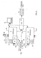
- the output of the sonar per se is four baseband signals comprising the four sets of demodulated echoes which may be used directly to produce a non-synthetic real time display ( Figure 1) or stored in a 4-channel tape recorder 6 for subsequent processing into a synthetic aperture image ( Figure 2).
- the two signals from each sonar channel are passed to a two channel spectrum analyser 9 (and 26) which comprises a two channel analogue to digital (A/D) converter 10 (and 24) followed by an array processor 11 (and 25) optimised for the Fast Fourier Transform (FFT).
- the computer 7 (and 22) requires a hard disk 8 (and 23) with a floppy disk drive (which-may be shared) 30.
- the controlling terminal 14 is attached to both computers 15 and 29.
- the computer 7 (and 22) has a video display controller to provide output 16 (and 27) to drive the left and right displays 12 and 28.
- Figure 2 shows an extension to the figure 1 system to produce a high quality high resolution synthetic aperture image from the previously stored demodulated echoes.
- the tape recorder 6 is rewound and used in the playback mode 32 with a closed loop speed control 33.
- the two right signals 34 and 35 and the two left signals 36 and 37 are again passed into the spectrum analysers 9 and 26. Since the synthetic aperture calculation is lengthy, real time operation is not yet possible so the set of spectral outputs representing some km of sonar movement is stored on the hard disks 8 and 23. When the disks are full the tape recorder halts.
- the computers 7 and 22, the spectrum analysers 9 and 26, the hard disks 8 and 23, the terminal 14 and the floppy disk drives are the same as those used for the real time mode; only the software used to run the computers is changed.
- the final synthetic aperture map is passed via interface 45 to a printer or facsimile machine 46 to produce a side scan synthetic aperture sonar map or image 47 of the sea floor.
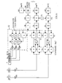
- FIG 3 the details of the dual demodulation receiver and transmitter system for a single channel (right channel) are shown.
- the entire system is controlled by a precision crystal master clock 88 the output of which is divided down by divider 87, and counter 86 to a suitable sub-master clock frequency. This can be altered by a counter 86 if the maximum range is altered.
- the sub-master clock signal controls the transmitter 52 sweep frequency synthesiser 66.
- the transmitting transducer 1 in Figure 1 is physically divided into 3 sections 54, 55 and 56. This technique ensures constant beamwidth.
- the centre section 54 is activated. At mid frequencies the centre two sections 54 and 55 are activated while at the lowest frequency all three section 54, 55 and 56 are activated.
- the precise waveform sent to each section is controlled by three EPROMs 63, 64, 65 coupled to three Multiplying Digital to Analogue converters (MDAC) 60, 61 62 driving three power amplifiers 57, 58, 59.
- MDAC Multiplying Digital to Analogue converters
- the received echoes are detected by the hydrophones 3 and 2, amplified by amplifiers 67 and 68 and passed to dual demodulators 69 and 70 for Rl with 78 and 79 for R2.
- the second inputs of the demodulators are supplied by individual swept frequency synthesisers 71, 72, 81, 82.
- the outputs of each pair of demodulators are fed to summers 73 and 80.
- the synthesisers (as with synthesiser 66) are configured to produce frequencies covering different ranges. This is so the outputs of summers 73 and 80 have the wanted frequencies at an intermediate frequency (IF) range which may be range corrected to remove unwanted frequencies by bandpass filters 74 and 83.
- IF intermediate frequency
- IF signals are then fed to demodulators 75 and 84 which produce baseband using a fixed frequency local oscillator 76.
- demodulators 75 and 84 which produce baseband using a fixed frequency local oscillator 76.
- two low pass filters 77 and 85 remove the sum frequency products generated by demodulators 75 and 84.
- the outputs of the right channel of the CTFM sonar are two sonar signals 91 and 92 representing the demodulated echoes from hydrophones 2 and 3.
- a synchronising signal 90 from divider 89 fed from the master clock 88 may be used for tape recorder speed control.
Landscapes
- Engineering & Computer Science (AREA)
- Radar, Positioning & Navigation (AREA)
- Remote Sensing (AREA)
- Physics & Mathematics (AREA)
- Acoustics & Sound (AREA)
- Computer Networks & Wireless Communication (AREA)
- General Physics & Mathematics (AREA)
- Measurement Of Velocity Or Position Using Acoustic Or Ultrasonic Waves (AREA)
Applications Claiming Priority (2)
| Application Number | Priority Date | Filing Date | Title |
|---|---|---|---|
| NZ211249 | 1985-04-20 | ||
| NZ21124985 | 1985-04-20 |
Publications (1)
| Publication Number | Publication Date |
|---|---|
| EP0199571A1 true EP0199571A1 (fr) | 1986-10-29 |
Family
ID=19921106
Family Applications (1)
| Application Number | Title | Priority Date | Filing Date |
|---|---|---|---|
| EP86302977A Withdrawn EP0199571A1 (fr) | 1985-04-20 | 1986-04-21 | Sonar à antenne synthétique et à émission continue |
Country Status (1)
| Country | Link |
|---|---|
| EP (1) | EP0199571A1 (fr) |
Cited By (12)
| Publication number | Priority date | Publication date | Assignee | Title |
|---|---|---|---|---|
| EP0282265A3 (fr) * | 1987-03-05 | 1989-11-15 | British Aerospace Public Limited Company | Systèmes de représentation |
| EP0393269A1 (fr) * | 1987-08-21 | 1990-10-24 | The Marconi Company Limited | Télémètre |
| GB2294763A (en) * | 1994-10-18 | 1996-05-08 | Willacy Oil Services Ltd | Determining sludge topography in oil tanks |
| EP1089092A1 (fr) * | 1999-10-01 | 2001-04-04 | Baggermaatschappij Boskalis B.V. | Méthode et appareil pour la mesure de paramètres physiques à partir des histoires de phase et d'amplitude d'un signal acoustique |
| RU2510045C2 (ru) * | 2012-02-27 | 2014-03-20 | Открытое акционерное общество "Государственный научно-исследовательский навигационно-гидрографический институт" (ОАО "ГНИНГИ") | Фазовый гидролокатор бокового обзора |
| EP3018494A1 (fr) * | 2014-11-07 | 2016-05-11 | Furuno Electric Company Limited | Appareil de détection ctfm et appareil de détection sous-marine |
| US10215849B2 (en) | 2016-04-27 | 2019-02-26 | Furuno Electric Co., Ltd. | CTFM detection apparatus and underwater detection apparatus |
| US10481248B2 (en) | 2015-12-11 | 2019-11-19 | Furuno Electric Co., Ltd. | Detection apparatus, underwater detection apparatus and radar apparatus |
| US10536320B2 (en) | 2015-06-15 | 2020-01-14 | Optimal Systems Laboratory, Inc. | Cancellation systems, methods, apparatuses, and software for acoustic or electromagnetic measurement or communications |
| CN109709562B (zh) * | 2018-11-08 | 2023-08-29 | 中国船舶重工集团公司七五0试验场 | 一种探测声纳的目标分辨数据处理方法 |
| CN116990791A (zh) * | 2023-09-25 | 2023-11-03 | 海底鹰深海科技股份有限公司 | 一种多接收阵合成孔径声纳回波仿真方法 |
| CN118363027A (zh) * | 2024-03-08 | 2024-07-19 | 哈尔滨工程大学 | 一种结合多角度信息的深海双基地三维定位方法及系统 |
Citations (5)
| Publication number | Priority date | Publication date | Assignee | Title |
|---|---|---|---|---|
| US3790939A (en) * | 1972-05-12 | 1974-02-05 | J Constant | Real time synthetic radar |
| US4244036A (en) * | 1978-12-21 | 1981-01-06 | Westinghouse Electric Corp. | Electronic stabilization for displaced phase center systems |
| EP0028895A1 (fr) * | 1979-11-07 | 1981-05-20 | National Aeronautics And Space Administration | Procédé et appareil pour former et diriger des faisceaux étroits |
| EP0048170A1 (fr) * | 1980-09-17 | 1982-03-24 | Gec Avionics Limited | Système radar de détermination de portée |
| US4400803A (en) * | 1981-05-26 | 1983-08-23 | The United States Of America As Represented By The Secretary Of The Navy | Wide swath precision echo sounder |
-
1986
- 1986-04-21 EP EP86302977A patent/EP0199571A1/fr not_active Withdrawn
Patent Citations (5)
| Publication number | Priority date | Publication date | Assignee | Title |
|---|---|---|---|---|
| US3790939A (en) * | 1972-05-12 | 1974-02-05 | J Constant | Real time synthetic radar |
| US4244036A (en) * | 1978-12-21 | 1981-01-06 | Westinghouse Electric Corp. | Electronic stabilization for displaced phase center systems |
| EP0028895A1 (fr) * | 1979-11-07 | 1981-05-20 | National Aeronautics And Space Administration | Procédé et appareil pour former et diriger des faisceaux étroits |
| EP0048170A1 (fr) * | 1980-09-17 | 1982-03-24 | Gec Avionics Limited | Système radar de détermination de portée |
| US4400803A (en) * | 1981-05-26 | 1983-08-23 | The United States Of America As Represented By The Secretary Of The Navy | Wide swath precision echo sounder |
Non-Patent Citations (7)
| Title |
|---|
| 1979 INTERNATIONAL SYMPOSIUM ON CIRCUITS AND SYSTEMS, PROCEEDINGS, Tokyo, JP, 17th-19th July 1979, pages 979,980, IEEE catalog no. 79CH1421-7 CAS; W.K. JENKINS: "Techniques in digital signal processing for synthetic aperture radar" * |
| ELECTRONICS LETTERS, vol. 17, no. 22, 29th October 1971, pages 841,842, London, GB; D.I. SHAW et al.: "Pseudostereoscopic holographic imaging system: a possible approach to high resolution underwater mapping" * |
| IEEE PROCEEDINGS, vol. 132, part F, no. 1, February 1985, pages 45-57, Stevenage, Herts, GB; M. SACK et al.: "Application of efficient linear FM matched filtering algorithms to synthetic aperture radar processing" * |
| JOURNAL OF THE ACOUSTICAL SOCIETY OF AMERICA, vol. 62, no. 2, August 1977, pages 341-345, The Acoustical Society of America, New York, US; T. SATO et al.: "Super-resolution ultrasonic imaging by combined spectral and aperture synthesis" * |
| PROCEEDINGS OF THE INSTITUTION OF ELECTRICAL ENGINEERS, vol. 107, part B, no. 34, July 1960, pages 365-372, London, GB; A.J. HYMANS et al.: "Analysis of a frequency-modulated continuous-wave ranging system" * |
| SYNTHETIC APERTURE RADAR, 1976, pages 32-54, Artech House Inc., Dedham, US; J.J. KOVALY: "Radar techniques for planetary mapping with orbiting vehicle" * |
| ULTRASONICS, vol. 16, no. 6, November 1978, pages 251-258, IPC Business Press, Guildford, GB; G. BERBEKAR et al.: "Hologram aperture synthesis with frequency sweeping" * |
Cited By (14)
| Publication number | Priority date | Publication date | Assignee | Title |
|---|---|---|---|---|
| EP0282265A3 (fr) * | 1987-03-05 | 1989-11-15 | British Aerospace Public Limited Company | Systèmes de représentation |
| EP0393269A1 (fr) * | 1987-08-21 | 1990-10-24 | The Marconi Company Limited | Télémètre |
| GB2294763A (en) * | 1994-10-18 | 1996-05-08 | Willacy Oil Services Ltd | Determining sludge topography in oil tanks |
| GB2294763B (en) * | 1994-10-18 | 1998-08-26 | Willacy Oil Services Ltd | Sludge topography measurement in oil tanks |
| EP1089092A1 (fr) * | 1999-10-01 | 2001-04-04 | Baggermaatschappij Boskalis B.V. | Méthode et appareil pour la mesure de paramètres physiques à partir des histoires de phase et d'amplitude d'un signal acoustique |
| RU2510045C2 (ru) * | 2012-02-27 | 2014-03-20 | Открытое акционерное общество "Государственный научно-исследовательский навигационно-гидрографический институт" (ОАО "ГНИНГИ") | Фазовый гидролокатор бокового обзора |
| EP3018494A1 (fr) * | 2014-11-07 | 2016-05-11 | Furuno Electric Company Limited | Appareil de détection ctfm et appareil de détection sous-marine |
| US10536320B2 (en) | 2015-06-15 | 2020-01-14 | Optimal Systems Laboratory, Inc. | Cancellation systems, methods, apparatuses, and software for acoustic or electromagnetic measurement or communications |
| US10481248B2 (en) | 2015-12-11 | 2019-11-19 | Furuno Electric Co., Ltd. | Detection apparatus, underwater detection apparatus and radar apparatus |
| US10215849B2 (en) | 2016-04-27 | 2019-02-26 | Furuno Electric Co., Ltd. | CTFM detection apparatus and underwater detection apparatus |
| CN109709562B (zh) * | 2018-11-08 | 2023-08-29 | 中国船舶重工集团公司七五0试验场 | 一种探测声纳的目标分辨数据处理方法 |
| CN116990791A (zh) * | 2023-09-25 | 2023-11-03 | 海底鹰深海科技股份有限公司 | 一种多接收阵合成孔径声纳回波仿真方法 |
| CN116990791B (zh) * | 2023-09-25 | 2023-11-28 | 海底鹰深海科技股份有限公司 | 一种多接收阵合成孔径声纳回波仿真方法 |
| CN118363027A (zh) * | 2024-03-08 | 2024-07-19 | 哈尔滨工程大学 | 一种结合多角度信息的深海双基地三维定位方法及系统 |
Similar Documents
| Publication | Publication Date | Title |
|---|---|---|
| US4216537A (en) | Sonar for the topographic representation of a submerged surface and underlying strata | |
| US20250123393A1 (en) | Sonar data compression | |
| US5455806A (en) | Multi-dimensional signal processing and display | |
| US6066099A (en) | Method and apparatus for high-frame-rate high-resolution ultrasonic image data acquisition | |
| JP4717995B2 (ja) | 超音波ビーム経路の数値的最適化方式 | |
| US20020126577A1 (en) | Multibeam synthetic aperture sonar | |
| EP0199571A1 (fr) | Sonar à antenne synthétique et à émission continue | |
| Gough | A synthetic aperture sonar system capable of operating at high speed and in turbulent media | |
| Pinto et al. | Real-and synthetic-array signal processing of buried targets | |
| Gough et al. | Test results using a prototype synthetic aperture sonar | |
| JP7255178B2 (ja) | ソーナー装置、方法、及びプログラム | |
| US4972387A (en) | High information rate catacoustic system | |
| US3435407A (en) | High speed system for processing long range sonar pulses | |
| US3914729A (en) | Underwater acoustic surveillance of harbor and channel areas | |
| US11187801B2 (en) | Spiral sonar | |
| Schock et al. | Sonar for multi-aspect buried mine imaging | |
| Hayes et al. | Test results from a multi-frequency bathymetric synthetic aperture sonar | |
| Talukdar et al. | Sidescan survey results from a multibeam sonar system—SEA BEAM 2000 | |
| Andrews et al. | Swathmap: Long range sidescan sonar mapping of the deep seafloor | |
| GB2314628A (en) | Acoustic and radar direction finding | |
| Blanford et al. | Design and evaluation of a compact correlation velocity log for small underwater vehicles | |
| Hughes | Sonar imaging with the synthetic aperture technique | |
| Dutkiewicz et al. | Synthetic aperture sonar for sub-bottom imaging | |
| Kritz | Parametric array Doppler sonar (PADS) | |
| Kirkebø | Beamforming for Imaging: A Brief Overview |
Legal Events
| Date | Code | Title | Description |
|---|---|---|---|
| PUAI | Public reference made under article 153(3) epc to a published international application that has entered the european phase |
Free format text: ORIGINAL CODE: 0009012 |
|
| AK | Designated contracting states |
Kind code of ref document: A1 Designated state(s): DE FR GB IT |
|
| 17P | Request for examination filed |
Effective date: 19870427 |
|
| 17Q | First examination report despatched |
Effective date: 19880915 |
|
| STAA | Information on the status of an ep patent application or granted ep patent |
Free format text: STATUS: THE APPLICATION IS DEEMED TO BE WITHDRAWN |
|
| 18D | Application deemed to be withdrawn |
Effective date: 19890117 |