EP0199578B1 - Structure possédant un panneau mobile - Google Patents
Structure possédant un panneau mobile Download PDFInfo
- Publication number
- EP0199578B1 EP0199578B1 EP86303016A EP86303016A EP0199578B1 EP 0199578 B1 EP0199578 B1 EP 0199578B1 EP 86303016 A EP86303016 A EP 86303016A EP 86303016 A EP86303016 A EP 86303016A EP 0199578 B1 EP0199578 B1 EP 0199578B1
- Authority
- EP
- European Patent Office
- Prior art keywords
- panel
- channel
- flush
- plane
- movable panel
- Prior art date
- Legal status (The legal status is an assumption and is not a legal conclusion. Google has not performed a legal analysis and makes no representation as to the accuracy of the status listed.)
- Expired
Links
- 238000005192 partition Methods 0.000 claims description 2
- 239000000969 carrier Substances 0.000 description 4
- 230000005484 gravity Effects 0.000 description 2
- 230000004075 alteration Effects 0.000 description 1
- 230000000694 effects Effects 0.000 description 1
- 239000011521 glass Substances 0.000 description 1
- 238000000034 method Methods 0.000 description 1
- 230000000717 retained effect Effects 0.000 description 1
- 238000005096 rolling process Methods 0.000 description 1
- 239000007787 solid Substances 0.000 description 1
- 239000012780 transparent material Substances 0.000 description 1
Images


Classifications
-
- E—FIXED CONSTRUCTIONS
- E05—LOCKS; KEYS; WINDOW OR DOOR FITTINGS; SAFES
- E05D—HINGES OR SUSPENSION DEVICES FOR DOORS, WINDOWS OR WINGS
- E05D15/00—Suspension arrangements for wings
- E05D15/06—Suspension arrangements for wings for wings sliding horizontally more or less in their own plane
- E05D15/10—Suspension arrangements for wings for wings sliding horizontally more or less in their own plane movable out of one plane into a second parallel plane
- E05D15/1065—Suspension arrangements for wings for wings sliding horizontally more or less in their own plane movable out of one plane into a second parallel plane with transversely moving track
-
- E—FIXED CONSTRUCTIONS
- E05—LOCKS; KEYS; WINDOW OR DOOR FITTINGS; SAFES
- E05D—HINGES OR SUSPENSION DEVICES FOR DOORS, WINDOWS OR WINGS
- E05D15/00—Suspension arrangements for wings
- E05D15/06—Suspension arrangements for wings for wings sliding horizontally more or less in their own plane
- E05D15/10—Suspension arrangements for wings for wings sliding horizontally more or less in their own plane movable out of one plane into a second parallel plane
- E05D15/1065—Suspension arrangements for wings for wings sliding horizontally more or less in their own plane movable out of one plane into a second parallel plane with transversely moving track
- E05D2015/1084—Suspension arrangements for wings for wings sliding horizontally more or less in their own plane movable out of one plane into a second parallel plane with transversely moving track the carriage being directly linked to the fixed frame, e.g. slidingly
-
- E—FIXED CONSTRUCTIONS
- E05—LOCKS; KEYS; WINDOW OR DOOR FITTINGS; SAFES
- E05Y—INDEXING SCHEME ASSOCIATED WITH SUBCLASSES E05D AND E05F, RELATING TO CONSTRUCTION ELEMENTS, ELECTRIC CONTROL, POWER SUPPLY, POWER SIGNAL OR TRANSMISSION, USER INTERFACES, MOUNTING OR COUPLING, DETAILS, ACCESSORIES, AUXILIARY OPERATIONS NOT OTHERWISE PROVIDED FOR, APPLICATION THEREOF
- E05Y2201/00—Constructional elements; Accessories therefor
- E05Y2201/60—Suspension or transmission members; Accessories therefor
- E05Y2201/622—Suspension or transmission members elements
- E05Y2201/628—Bearings
-
- E—FIXED CONSTRUCTIONS
- E05—LOCKS; KEYS; WINDOW OR DOOR FITTINGS; SAFES
- E05Y—INDEXING SCHEME ASSOCIATED WITH SUBCLASSES E05D AND E05F, RELATING TO CONSTRUCTION ELEMENTS, ELECTRIC CONTROL, POWER SUPPLY, POWER SIGNAL OR TRANSMISSION, USER INTERFACES, MOUNTING OR COUPLING, DETAILS, ACCESSORIES, AUXILIARY OPERATIONS NOT OTHERWISE PROVIDED FOR, APPLICATION THEREOF
- E05Y2900/00—Application of doors, windows, wings or fittings thereof
- E05Y2900/20—Application of doors, windows, wings or fittings thereof for furniture, e.g. cabinets
- E05Y2900/202—Application of doors, windows, wings or fittings thereof for furniture, e.g. cabinets for display cabinets, e.g. for refrigerated cabinets
Definitions
- the present invention relates to a structure having a movable panel.
- slidable or rollable devices to transfer a movable panel out of a flush-fitting plane into a parallel non-flush plane and to move the panel in a lateral manner such that an opening in the structure is presented.
- the known means for transferring the panel between planes may be provided by sets of slidable extension devices mounted perpendicular to the panel and positioned at the top and bottom thereof, and at additional intermediate positions for large panels. There is no guarantee of simultaneous movement of the extension devices since even movement of the panel is difficult and may be impossible with large panels. This may result in excessive stresses in the panel and any means allowing lateral movement thereof such that operation becomes difficult.
- DE-A-3 142 431 shows a structure of this type but having a single extension device positioned at the top of the vertical panel and from which the vertical panel is hung.
- the lower edge extends simultaneously since it is not held but is allowed to follow the movement of the upper edge under the forces of gravity.
- the panel therefore remains in a vertical plane during extension. The fact that the panel is supported only along the upper edge thereof makes the panel awkward to manoeuvre.
- the upper edge of the panel is retained in a groove and slides therein when the panel is moved laterally.
- the fitting of the panel in the groove and also onto the extension device must be loose since the panel is allowed to tilt into a slightly inclined plane for sliding. This impairs the flush-fitting of the movable panel in relation to the adjacent panels. If the fitting of the panel in the groove and onto the extension device is tightened, the tilting movement and the lateral movement are hindered and make the panel difficult to manoeuvre.
- the same document discloses a structure having extension devices at the top and bottom edges of a movable panel.
- the extension devices have loose-fitting roller-and-track means whereby the panel can be extended into a non-flush plane without the panel necessarily remaining perfectly parallel to its flush fitting plane. A small amount of tilting is allowed. However, if any such tilting did occur, severe stresses would be imposed on the rollers which would be forced to tilt with the panel.
- An object of the invention is to obviate the need for even movement of the panel between planes and to reduce considerably the difficulties concerned with lateral movement of angled panels.
- the invention provides a structure comprising a support frame having a front portion and two side portions, the side portions being slidably mounted on supports to allow sliding movement of the frame between a retracted and an extended position, a movable panel mounted on the said front portion of the frame via interengaging track means allowing a first tilting of the movable panel (relative to the said front portion from a flush-fitting plane to an inclined plane on sliding movement of the frame from the retracted to the extended position, characterised in that the interengaging track means allow a subsequent second tilting of the movable panel from the said inclined plane to a non-flush plane substantially parallel to the flush-fitting plane to allow lateral sliding of the movable panel along the said front portion, and comprise a channel having opposed arcuate surfaces and channel-engaging means having opposed arcuate surfaces engaging those of the channel and allowing relative rotation between the channel and the channel-engaging means about a longitudinal axis of the channel to facilitate the first and second tilting, -the arcuate surfaces
- the interengaging track means may comprise a part-circular track engageable by part-spherical rollers or wheels or by carriers presenting ball race abutments or pairs or sets of wheels to the track.
- the track may be slidably engageable by a rod of substantially part-circular cross section. The tilting movement is facilitated by the rotation of the rollers, wheels, carriers or rod in the track in the plane of part-circular cross section and about the center of curvature thereof, while the lateral movement is facilitated by the rolling of the rollers, wheels or carriers or by the sliding of the rod in the track.
- the extension devices facilitating movement of the panel between the flush-fitting and non-flush planes are mounted on the side portions of the frame. These devices may be any slid-
- able device but are preferably of the same type used to facilitate tilting and lateral movement.
- the frame is connected to the structure by the interengaging track means and extension devices which may be mounted directly on the panels of the structure.
- a large internal frame is not required and the panels may be easily and directly connected so as to support each other.
- At least two frames as described above may be present in the structure according to the invention. These may be located at the top and bottom of the panel and at any intermediate position therebetween.
- the tilting means allow one end of the panel to be extended between the flush-fitting and non-flush planes before the opposite end is moved.
- the movable panel may be extended into the non-flush plane and moved laterally into an open position by one person.
- the tilting means also allow the movable panel to remain angled to the vertical at all times without requiring any adjustment to the components of the frame and means attached thereto, by virtue of the relative rotatability of the rollers, wheels, carriers or rod and the track.
- the present invention may be applied to any structure requiring an openable flush-fitting panel with a concealed mechanism.
- it may be applied to a showcase or display unit where the panels are made of glass or similar transparent material and each panel forms one complete side of the unit.
- the movable panel may form part of a large flush fitting planar structure, for example a floor, wall or ceiling.
- the invention may equally be applied to partitions, window displays, museum display panels and structures, access panegs and doors in machinery, vehicles, plant and containers, building, domestic and commercial furniture systems.
- a track 1 is mounted on a movable panel 5 and comprises an extruded or rolled main profile having a main channel of part-circular cross section 3 and may have additional channels, abutments or linear form screw threads 6 for additional or corner fixing. Fitting closely into the main channel 3 are wheels or rollers 2 having a part-spherical shape, being carried on axles 4 and mounted on the front section of a frame 8. It will be appreciated that the track and roller configuration may be reversed, the track 1 being attached to the frame 8 and the rollers 2 being mounted on the panel 5.
- rollers 2 and channel 3 allow the tilting movement to take place as shown in Figure 2, occurring when the panel 5 is extended at the top or bottom only. Excessive rotation is prevented by contact of the roller 2 with a protruding lip 7.
- Figures 3a and 3b show an arrangement comprising a carrier 12 on which are mounted pairs of part-spherical rollers 13 such that the rollers 13 engage with the track.
- Figures 4a and 4b show a similar arrangement comprising a carrier 14 having ballrace abutments 15 engaging with the track 1.
- Figures 5a and 5b show an arrangement having a solid bar 16 of part-circular cross section slidably and rotatably mounted in the track 1.
- the frame 8 is shaped such that two side portions extend horizontally from the front portion in a direction perpendicular to the front portion.
- the side portions may be parallel to fixed side panels and may be attached thereto.
- the frame 8 is positioned such that the front portion 8a is parallel to the movable panel 5, and the side portion 8b is parallel to side panel 9.
- Tracks 1 a, 1 b are attached to the panels 5, 9 respectively; track 1 a having the particular cross section described above.
- Track 1 b is preferably of the same cross section.
- a plurality of rollers 2a engage track 1a and a further plurality of rollers 2b engage track 1 b.
- Two frames 8 are provided one positioned at the top of the movable panel and the second at the bottom. Means (not shown) may be provided such that the extension and lateral movement is limited so as to prevent total disengagement of the tracks 1a, 1 from the rollers 2a, 2b.
- rollers 2a, 2b make contact with the tracks 1 a, 1 b and the movable panel 5 is fitted flush to the side panel 9.
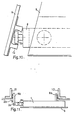
- one end may be extended before the other as shown in Figure 8.
- the rollers 2b and track 1 b of the upper frame 8 move slidably to extend the top end of panel 5, while the rollers 2a of both frames 8 rotate in the part-circular tracks 1a without lateral motion, such that the panel 5 is tilted.
- the bottom end may then be extended in a similar way, the rollers 2b and track 1 of the lower frame moving slidably to allow extension to occur.
- the rollers 2a rotate in the tracks 1a back to their original positions, again without lateral motion.
- the extended position is shown in Figure 9.
- the panel 5 may then be moved laterally by sliding of the rollers 2a in track 1a such that an opening is provided in the panelled structure.
- the panel may be closed by reversal of the above procedure.
- FIG 10 an embodiment having inclined panels is described.
- the frame 8 is horizontal and tracks are attached to both the movable and fixed panels 5, 9.
- the part-circular track 1b allows the rollers 2b to operate in a permanently tilted position. This arrangement may impose a particular order in which the ends of the movable panel 5 may be extended due to limitation of rotation of the rollers 2b relative to the track 1 b.
- the panel 5 should preferably be extended such that the first end to be extended reduces the angle of incline to the vertical. Once the panel 5 is in the non-flush plane, lateral movement may take place as described above.
- the movable panel 5 lies flush with adjacent panels in the fully closed position.
- the side portions 8b of the frame extend vertically from the front portion 8a and carry rollers 2b engageable in tracks 1 b so as to facilitate vertical movement of the panel 5 between the flush-fitting and non-flush planes.
- Means (not shown) may be provided to allow the panel to be held in the fully closed position.
- Two frames 8 are provided on opposite side of the movable panel 5.
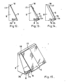
- Figures 12 to 15 relate to an embodiment of the invention having an inclined movable panel 5 and having one frame 8 located at the bottom of panel 5.
- the upper end 17 of panel 5 is trapped under a trapping channel 18 when in the fully closed position shown in Figure 12.
- rollers 2b are moved slidably in tracks (not shown) such that the lower end of panel 5 is extended as shown in Figure 13.
- the extension causes the upper end 17 to move in the direction of the arrow to a position where it is no longer trapped by the trapping channel 18.
- Resilient means (not shown) are attached such that when the upper end 17 is clear of the trapping channel 18, the panel 5 rotates about rollers 2a until the required position in the non-flush plane is achieved as shown in Figure 14. Lateral motion is now possible and the structure with the panel 5 in the open position is shown in Figure 15.
Landscapes
- Engineering & Computer Science (AREA)
- Mechanical Engineering (AREA)
- Support Devices For Sliding Doors (AREA)
- Freezers Or Refrigerated Showcases (AREA)
- Rollers For Roller Conveyors For Transfer (AREA)
Claims (23)
Applications Claiming Priority (4)
| Application Number | Priority Date | Filing Date | Title |
|---|---|---|---|
| GB8510235 | 1985-04-22 | ||
| GB8510235A GB8510235D0 (en) | 1985-04-22 | 1985-04-22 | Rolling door mechanism |
| GB8529728 | 1985-12-03 | ||
| GB8529728A GB2179085A (en) | 1985-04-22 | 1985-12-03 | Movable panel |
Publications (2)
| Publication Number | Publication Date |
|---|---|
| EP0199578A1 EP0199578A1 (fr) | 1986-10-29 |
| EP0199578B1 true EP0199578B1 (fr) | 1989-09-20 |
Family
ID=26289153
Family Applications (1)
| Application Number | Title | Priority Date | Filing Date |
|---|---|---|---|
| EP86303016A Expired EP0199578B1 (fr) | 1985-04-22 | 1986-04-22 | Structure possédant un panneau mobile |
Country Status (4)
| Country | Link |
|---|---|
| US (1) | US4716693A (fr) |
| EP (1) | EP0199578B1 (fr) |
| AU (1) | AU582645B2 (fr) |
| ES (1) | ES8705608A1 (fr) |
Cited By (1)
| Publication number | Priority date | Publication date | Assignee | Title |
|---|---|---|---|---|
| CN101037914B (zh) * | 2006-03-16 | 2012-01-25 | 固力有限公司 | 铰链及其组件 |
Families Citing this family (39)
| Publication number | Priority date | Publication date | Assignee | Title |
|---|---|---|---|---|
| US5257481A (en) * | 1989-01-25 | 1993-11-02 | George S. Reppas | Retractable dome |
| US5067287A (en) * | 1990-06-25 | 1991-11-26 | Lewis Kenneth T | Display wall assembly |
| US5873205A (en) * | 1990-11-28 | 1999-02-23 | Advantage Office Systems, Llc | Privacy panel for use with open office furniture systems |
| US5345723A (en) * | 1992-01-21 | 1994-09-13 | Ameristar Fence Products, Inc. | Gate conversion method |
| US5272838A (en) * | 1992-01-21 | 1993-12-28 | Ameristar Fence Products, Inc. | Gate conversion kit |
| US5297368A (en) * | 1992-05-11 | 1994-03-29 | Okada Paul M | Movable wall system |
| AR247854A1 (es) * | 1993-03-05 | 1995-04-28 | Ingenieria Moderna S A | Disposicion de puerta corrediza para vehiculos |
| US5632119A (en) * | 1993-03-05 | 1997-05-27 | Eduardo V. Bruno | Sliding door arrangement for a containment space |
| CH687836A5 (de) * | 1994-11-09 | 1997-02-28 | Mettler Toledo Ag | Windschutz fur eine Waage. |
| US5778603A (en) * | 1996-10-29 | 1998-07-14 | Reppas; George S. | Retractable dome |
| US5791094A (en) * | 1997-01-09 | 1998-08-11 | Diverse Industries, Inc. | Movable wall for ball court |
| GB2354426B (en) | 1999-09-25 | 2004-03-24 | Netherfield Visual Ltd | Side wall mounting for a showcase |
| US7604481B2 (en) * | 2004-01-16 | 2009-10-20 | Meadwestvaco Corporation | White board and white board display system |
| US7594360B2 (en) * | 2005-03-09 | 2009-09-29 | Uni-Systems, Llc | Lateral release mechanism for movable roof panels |
| US7685775B2 (en) * | 2005-12-30 | 2010-03-30 | Speyer Door And Window, Inc. | Combined sealing systems for sliding door/window |
| US7707773B2 (en) * | 2005-12-30 | 2010-05-04 | Speyer Door And Window, Inc. | Seal activation system positioned within panel for door/window |
| US7685776B2 (en) * | 2005-12-30 | 2010-03-30 | Speyer Door And Window, Inc. | Sealing system for sliding door/window |
| US8109037B2 (en) | 2005-12-30 | 2012-02-07 | Secura-Seal Technologies Llc | Active sealing system for single-hung door/window |
| US8627606B2 (en) | 2005-12-30 | 2014-01-14 | Tyto Life LLC | Combined sealing system for garage door |
| US8925249B2 (en) * | 2006-06-20 | 2015-01-06 | Tyto Life LLC | Active sealing and securing systems for door/window |
| US8074400B2 (en) * | 2006-06-20 | 2011-12-13 | Secura-Seal Technologies Llc | Combined modular sealing systems and seal activation system for door/window |
| US8091282B2 (en) * | 2005-12-30 | 2012-01-10 | Secura-Seal Technologies Llc | Combined sealing system and seal activation system for door/window |
| US8539717B2 (en) * | 2005-12-30 | 2013-09-24 | Secura-Seal Technologies Llc | Electronic control for door/window |
| US7685774B2 (en) * | 2005-12-30 | 2010-03-30 | Speyer Door And Window, Inc. | Closing system for sealing system of sliding door/window |
| US20070234657A1 (en) * | 2005-12-30 | 2007-10-11 | Speyer Door And Window, Inc. | Combination sealing system for sliding door/window |
| US8336258B2 (en) | 2005-12-30 | 2012-12-25 | Secura-Seal Technologies Llc | Self-driving combination sealing system for single-hung door/window |
| WO2007104950A1 (fr) * | 2006-03-16 | 2007-09-20 | Securistyle Limited | Charniere |
| US8074399B2 (en) * | 2006-06-20 | 2011-12-13 | Secura-Seal Technologies Llc | Sealing system modules for door/window |
| US20080295410A1 (en) * | 2007-06-01 | 2008-12-04 | Speyer Door And Window, Inc. | Acoustic/thermal break and framing system for door/window |
| US8468746B2 (en) | 2008-09-30 | 2013-06-25 | Tyto Life LLC | Sealing systems for garage door |
| US8484899B2 (en) * | 2008-09-30 | 2013-07-16 | Tyto Life LLC | Driving and driven sealing systems for single-hung door/window |
| US8516756B2 (en) * | 2009-04-27 | 2013-08-27 | Secura-Seal Technologies Llc | Door panel with thermal break |
| DE102011056400B3 (de) * | 2011-12-14 | 2013-05-29 | Sartorius Weighing Technology Gmbh | Lagerung für eine Seitenscheibe einer Waage, Baugruppe für einen Windschutz einer Waage sowie Verfahren zur Demontage einer Seitenscheibe einer solchen Baugruppe |
| DE202013102868U1 (de) * | 2013-07-01 | 2014-10-13 | Glasbau Hahn Gmbh | Vitrine für eine Aufstellfläche zur Zurschaustellung von Gegenständen |
| US9809049B2 (en) | 2013-10-04 | 2017-11-07 | Comsero, Inc. | Tablet with interconnection features |
| USD747955S1 (en) | 2014-05-08 | 2016-01-26 | Comsero, LLC | Mounting bracket |
| US12078292B2 (en) | 2015-11-06 | 2024-09-03 | Salto, Llc | Support assembly and mounting system |
| US11047160B2 (en) * | 2018-03-28 | 2021-06-29 | Salto, Llc | Sliding door mounting system |
| JP7083668B2 (ja) * | 2018-03-15 | 2022-06-13 | Ykk Ap株式会社 | 戸車、戸体及び建具 |
Family Cites Families (22)
| Publication number | Priority date | Publication date | Assignee | Title |
|---|---|---|---|---|
| US1988260A (en) * | 1934-01-02 | 1935-01-15 | Frank J Berghoff | Movable enclosure |
| GB433421A (en) * | 1934-01-08 | 1935-08-14 | Willy Stiegler | Improvements in or relating to sliding doors for garages and the like |
| GB425097A (en) * | 1934-10-25 | 1935-03-06 | Ernest Hill Aldam | Improvements in or relating to sliding doors, windows and the like |
| CH202802A (de) * | 1937-04-30 | 1939-02-15 | Ver Baubeschlag Gretsch Co | Schiebetürbeschlag. |
| US2736603A (en) * | 1954-03-19 | 1956-02-28 | Harold W Payne | Automobile door with upwardly folding lower section |
| DE1144602B (de) * | 1956-11-10 | 1963-02-28 | Daimler Benz Ag | Schiebetuer fuer Kraftfahrzeuge |
| US2992709A (en) * | 1957-05-16 | 1961-07-18 | James C Mcintosh | Airplane hangar |
| DE1268499B (de) * | 1961-02-16 | 1968-05-16 | Nsu Motorenwerke Ag | Schiebetuer fuer Fahrzeuge, insbesondere fuer Kraftfahrzeuge |
| GB1093768A (en) * | 1965-07-28 | 1967-12-06 | King Ltd Geo W | Improvements in or relating to suspension means for a sliding door |
| US3360136A (en) * | 1966-01-03 | 1967-12-26 | City Line Lumber Co | Display panel frame work |
| GB1180231A (en) * | 1966-02-08 | 1970-02-04 | A C Cars Ltd | Improvements in and relating to Doors for Vehicles |
| GB1197941A (en) * | 1967-05-02 | 1970-07-08 | Frank Hickson | Sliding Doors |
| GB1222959A (en) * | 1967-12-14 | 1971-02-17 | Newhall Metal Products Ltd | Sliding door gear |
| DE1784710B1 (de) * | 1968-09-10 | 1970-09-16 | Vaw Ag | Beschlag für einen waagerecht schiebbaren Flügel von Fenstern,Türen od. dgl. |
| DE2133756A1 (de) * | 1971-07-07 | 1973-01-25 | Dowaldwerke | Schiebetuer, insbesondere fuer fahrzeuge |
| GB1379627A (en) * | 1972-03-24 | 1975-01-02 | Beckett Laycock Watkinson Ltd | Sliding door assemblies |
| US4359249A (en) * | 1980-07-08 | 1982-11-16 | Glasbau Heinrich Hahn Gmbh & Co. Kg | Display case and a modular display case system |
| DE3033751C2 (de) * | 1980-09-08 | 1986-01-23 | Schaumburg-Lippische Baubeschlag-Fabrik W. Hautau GmbH, 3068 Helpsen | Beschlag für den Schiebeflügel von Fenstern, Türen oder dgl. aus Holz- oder Kunststoffprofilen |
| US4360991A (en) * | 1980-09-09 | 1982-11-30 | West Evelyn M | Movable room dividing partition |
| IT1208916B (it) * | 1981-09-17 | 1989-07-10 | Kairos Di Bonetti M Manente G | Dispositivo di apertura della ante scorrevoli allineate di mobili. |
| DE3142431A1 (de) * | 1981-10-26 | 1983-06-01 | Gebr. Schäffer GmbH & Co KG, 4970 Bad Oeynhausen | Schiebetuer mit zweirichtungsfuehrung |
| JPS593977U (ja) * | 1982-06-30 | 1984-01-11 | 日産車体株式会社 | 車輌用スライドドアのスライドガイド装置 |
-
1986
- 1986-04-22 EP EP86303016A patent/EP0199578B1/fr not_active Expired
- 1986-04-22 US US06/855,097 patent/US4716693A/en not_active Expired - Lifetime
- 1986-04-22 ES ES554252A patent/ES8705608A1/es not_active Expired
- 1986-04-22 AU AU56481/86A patent/AU582645B2/en not_active Ceased
Cited By (1)
| Publication number | Priority date | Publication date | Assignee | Title |
|---|---|---|---|---|
| CN101037914B (zh) * | 2006-03-16 | 2012-01-25 | 固力有限公司 | 铰链及其组件 |
Also Published As
| Publication number | Publication date |
|---|---|
| US4716693A (en) | 1988-01-05 |
| ES8705608A1 (es) | 1987-05-01 |
| ES554252A0 (es) | 1987-05-01 |
| EP0199578A1 (fr) | 1986-10-29 |
| AU582645B2 (en) | 1989-04-06 |
| AU5648186A (en) | 1986-10-30 |
Similar Documents
| Publication | Publication Date | Title |
|---|---|---|
| EP0199578B1 (fr) | Structure possédant un panneau mobile | |
| US4386645A (en) | Side folding closure | |
| US4680828A (en) | Hardware for mounting a sliding door panel | |
| US4998577A (en) | Device for stabilized opening and closing of a sliding panel | |
| US4660613A (en) | Folding closure assembly | |
| US4274688A (en) | Sliding door structure | |
| US11478088B2 (en) | Museum showcase with a guide system for a sliding door | |
| JPH02101275A (ja) | 滑動ドア | |
| CA1280317C (fr) | Structure a panneau mobile | |
| GB2179085A (en) | Movable panel | |
| US5072768A (en) | Hinge for folding closure | |
| US3260303A (en) | Multi-panel sliding door structure | |
| JP4750264B2 (ja) | 間仕切装置 | |
| JPH0438276B2 (fr) | ||
| GB2191528A (en) | Door for display cabinets | |
| US20220290478A1 (en) | Glass panel system | |
| JPH0527870Y2 (fr) | ||
| JP2579288B2 (ja) | 横引障子の移動収納装置 | |
| JPH04272350A (ja) | 自立折畳みパーティション | |
| JPH057058Y2 (fr) | ||
| JPH09209649A (ja) | 引戸用の上部案内装置 | |
| EP0362572A1 (fr) | Quincaillerie pour portes ou fenêtres coulissantes | |
| SU1641657A1 (ru) | Нижнее подвижное соединение сдвижной двери | |
| JPH10140920A (ja) | 間仕切り装置 | |
| CA3027605C (fr) | Systeme mural demontable |
Legal Events
| Date | Code | Title | Description |
|---|---|---|---|
| PUAI | Public reference made under article 153(3) epc to a published international application that has entered the european phase |
Free format text: ORIGINAL CODE: 0009012 |
|
| AK | Designated contracting states |
Kind code of ref document: A1 Designated state(s): FR GB IT NL SE |
|
| 17P | Request for examination filed |
Effective date: 19870202 |
|
| 17Q | First examination report despatched |
Effective date: 19871221 |
|
| ITF | It: translation for a ep patent filed | ||
| GRAA | (expected) grant |
Free format text: ORIGINAL CODE: 0009210 |
|
| AK | Designated contracting states |
Kind code of ref document: B1 Designated state(s): FR GB IT NL SE |
|
| ET | Fr: translation filed | ||
| PLBE | No opposition filed within time limit |
Free format text: ORIGINAL CODE: 0009261 |
|
| STAA | Information on the status of an ep patent application or granted ep patent |
Free format text: STATUS: NO OPPOSITION FILED WITHIN TIME LIMIT |
|
| 26N | No opposition filed | ||
| ITTA | It: last paid annual fee | ||
| PGFP | Annual fee paid to national office [announced via postgrant information from national office to epo] |
Ref country code: SE Payment date: 19930419 Year of fee payment: 8 |
|
| PG25 | Lapsed in a contracting state [announced via postgrant information from national office to epo] |
Ref country code: SE Effective date: 19940423 |
|
| EUG | Se: european patent has lapsed |
Ref document number: 86303016.9 Effective date: 19941110 |
|
| PGFP | Annual fee paid to national office [announced via postgrant information from national office to epo] |
Ref country code: FR Payment date: 19990426 Year of fee payment: 14 |
|
| PGFP | Annual fee paid to national office [announced via postgrant information from national office to epo] |
Ref country code: NL Payment date: 19990429 Year of fee payment: 14 |
|
| PG25 | Lapsed in a contracting state [announced via postgrant information from national office to epo] |
Ref country code: NL Free format text: LAPSE BECAUSE OF NON-PAYMENT OF DUE FEES Effective date: 20001101 |
|
| PG25 | Lapsed in a contracting state [announced via postgrant information from national office to epo] |
Ref country code: FR Free format text: LAPSE BECAUSE OF NON-PAYMENT OF DUE FEES Effective date: 20001229 |
|
| NLV4 | Nl: lapsed or anulled due to non-payment of the annual fee |
Effective date: 20001101 |
|
| REG | Reference to a national code |
Ref country code: FR Ref legal event code: ST |
|
| PGFP | Annual fee paid to national office [announced via postgrant information from national office to epo] |
Ref country code: GB Payment date: 20010418 Year of fee payment: 16 |
|
| REG | Reference to a national code |
Ref country code: GB Ref legal event code: IF02 |
|
| PG25 | Lapsed in a contracting state [announced via postgrant information from national office to epo] |
Ref country code: GB Free format text: LAPSE BECAUSE OF NON-PAYMENT OF DUE FEES Effective date: 20020422 |
|
| GBPC | Gb: european patent ceased through non-payment of renewal fee |
Effective date: 20020422 |
|
| PG25 | Lapsed in a contracting state [announced via postgrant information from national office to epo] |
Ref country code: IT Free format text: LAPSE BECAUSE OF NON-PAYMENT OF DUE FEES Effective date: 20050422 |