EP0199592A1 - Aufblasbares Gebäude - Google Patents
Aufblasbares Gebäude Download PDFInfo
- Publication number
- EP0199592A1 EP0199592A1 EP86303051A EP86303051A EP0199592A1 EP 0199592 A1 EP0199592 A1 EP 0199592A1 EP 86303051 A EP86303051 A EP 86303051A EP 86303051 A EP86303051 A EP 86303051A EP 0199592 A1 EP0199592 A1 EP 0199592A1
- Authority
- EP
- European Patent Office
- Prior art keywords
- inflatable
- building structure
- membrane
- support posts
- attached
- Prior art date
- Legal status (The legal status is an assumption and is not a legal conclusion. Google has not performed a legal analysis and makes no representation as to the accuracy of the status listed.)
- Granted
Links
- 239000012528 membrane Substances 0.000 claims abstract description 72
- 238000000034 method Methods 0.000 claims abstract description 24
- 230000002093 peripheral effect Effects 0.000 claims abstract description 15
- 230000000717 retained effect Effects 0.000 claims description 5
- 238000001125 extrusion Methods 0.000 description 4
- 239000011521 glass Substances 0.000 description 4
- 229910000831 Steel Inorganic materials 0.000 description 3
- 239000011324 bead Substances 0.000 description 3
- 238000009434 installation Methods 0.000 description 3
- 239000010959 steel Substances 0.000 description 3
- 241000238631 Hexapoda Species 0.000 description 2
- 230000000694 effects Effects 0.000 description 2
- 230000003028 elevating effect Effects 0.000 description 2
- 230000002787 reinforcement Effects 0.000 description 2
- 229910001335 Galvanized steel Inorganic materials 0.000 description 1
- 230000006835 compression Effects 0.000 description 1
- 238000007906 compression Methods 0.000 description 1
- 239000008397 galvanized steel Substances 0.000 description 1
- 238000010438 heat treatment Methods 0.000 description 1
- 238000011900 installation process Methods 0.000 description 1
- 238000009413 insulation Methods 0.000 description 1
- 230000014759 maintenance of location Effects 0.000 description 1
- 239000000463 material Substances 0.000 description 1
- 239000011159 matrix material Substances 0.000 description 1
- 239000002184 metal Substances 0.000 description 1
- 239000003973 paint Substances 0.000 description 1
- 229920003023 plastic Polymers 0.000 description 1
- 239000004033 plastic Substances 0.000 description 1
- 238000003466 welding Methods 0.000 description 1
Images


Classifications
-
- E—FIXED CONSTRUCTIONS
- E04—BUILDING
- E04B—GENERAL BUILDING CONSTRUCTIONS; WALLS, e.g. PARTITIONS; ROOFS; FLOORS; CEILINGS; INSULATION OR OTHER PROTECTION OF BUILDINGS
- E04B7/00—Roofs; Roof construction with regard to insulation
- E04B7/14—Suspended roofs
-
- A—HUMAN NECESSITIES
- A01—AGRICULTURE; FORESTRY; ANIMAL HUSBANDRY; HUNTING; TRAPPING; FISHING
- A01G—HORTICULTURE; CULTIVATION OF VEGETABLES, FLOWERS, RICE, FRUIT, VINES, HOPS OR SEAWEED; FORESTRY; WATERING
- A01G9/00—Cultivation in receptacles, forcing-frames or greenhouses; Edging for beds, lawn or the like
- A01G9/14—Greenhouses
- A01G9/1407—Greenhouses of flexible synthetic material
- A01G9/1415—Greenhouses of flexible synthetic material with double or multiple walls
-
- E—FIXED CONSTRUCTIONS
- E04—BUILDING
- E04H—BUILDINGS OR LIKE STRUCTURES FOR PARTICULAR PURPOSES; SWIMMING OR SPLASH BATHS OR POOLS; MASTS; FENCING; TENTS OR CANOPIES, IN GENERAL
- E04H15/00—Tents or canopies, in general
- E04H15/20—Tents or canopies, in general inflatable, e.g. shaped, strengthened or supported by fluid pressure
- E04H2015/202—Tents or canopies, in general inflatable, e.g. shaped, strengthened or supported by fluid pressure with inflatable panels, without inflatable tubular framework
- E04H2015/203—Tents or canopies, in general inflatable, e.g. shaped, strengthened or supported by fluid pressure with inflatable panels, without inflatable tubular framework supported by a non-inflatable structure or framework
-
- Y—GENERAL TAGGING OF NEW TECHNOLOGICAL DEVELOPMENTS; GENERAL TAGGING OF CROSS-SECTIONAL TECHNOLOGIES SPANNING OVER SEVERAL SECTIONS OF THE IPC; TECHNICAL SUBJECTS COVERED BY FORMER USPC CROSS-REFERENCE ART COLLECTIONS [XRACs] AND DIGESTS
- Y02—TECHNOLOGIES OR APPLICATIONS FOR MITIGATION OR ADAPTATION AGAINST CLIMATE CHANGE
- Y02A—TECHNOLOGIES FOR ADAPTATION TO CLIMATE CHANGE
- Y02A40/00—Adaptation technologies in agriculture, forestry, livestock or agroalimentary production
- Y02A40/10—Adaptation technologies in agriculture, forestry, livestock or agroalimentary production in agriculture
- Y02A40/25—Greenhouse technology, e.g. cooling systems therefor
Definitions
- THIS INVENTION relates to an inflatable building structure comprising a plurality of support posts and an inflatable roof.
- the building structure is especially adapted for use as a greenhouse, fernhouse or building mainly utilized for the propagation of plants.
- the building structure of the invention may be utilized for any other suitable purpose such as storage of perishable food articles.
- Hitherto building structures for plants are usually time consuming to erect especially conventional greenhouses which are used for large scale commercial growing of plants which require abundant exposure to light and appropriate insulation so as to maintain a controlled temperature within the greenhouse.
- the greenhouse was usually constructed in accordance with standard building practice wherein a basic frame was first erected and then transparent panels usually formed from glass were attached thereto to form both the roof and the walls of the greenhouse.
- the basic frame in requiring usually girders, beams and welding so as to interconnect adjacent frame members was expensive and time consuming in erection time.
- the addition of glass panels was also expensive and time consuming.
- the roof could not be satisfactorily insulated and thus such greenhouses were prone to heat loss at night.
- the process of the invention includes the following steps:
- the roof structure is formed from one or more roof membranes formed from transparent or at least translucent material wherein the roof membrane comprises an upper membrane usually in the form of a sheet and a lower membrane also usually in the form of a sheet which may be attached thereto along mutually adjacent side edges.
- a suitable membrane may have a pair of opposed side edges wherein the side edges are each attached to each 'other or to a gutter member or other appropriate rigid member.
- the roof structure may comprise a pair of outer gutter members or rigid peripheral members and a number of membranes interposed therebetween with adjacent membranes being interconnected by intermediate gutter members or intermediate rigid members.
- the inflatable membrane may be in form of an inflatable bag or mattress or other suitable integral structure.
- the adoption of an upper membrane and lower membrane is convenient because each membrane may have mutually adjacent edges which are attached to each other before being attached to an associated gutter member or rigid member.
- each adjacent side edge of lower membrane and upper membrane is attached to each other in the form of a continuous bead which then may be retained in a suitable supporting groove or slot in the gutter member or rigid member.
- the adjacent edges of both upper membrane and lower membrane may be separate from each other before attachment to the gutter member or rigid member.
- the former arrangement is preferred.
- the roof structure as discussed above in step (b) in a first embodiment may be placed or located in conjunction with the plurality of support posts such that the roof structure or roof structure component defined by a pair of gutter members or rigid members is initially laid on the ground between adjacent rows of support posts and hoisting cables are attached to the gutter members.
- the roof structure or portion thereof which was initially in a slack or loose condition when laid on the ground may then assume a taut attitude.
- the gutter members or rigid members may then be mounted on or supported by mounting brackets attached on the support posts adjacent the pulleys.
- the pulleys and hoisting cables may then be removed and the roof membrane or membranes inflated by appropriate means.
- an inflating duct or pipe may communicate with the interior of the membrane and air may be pumped in by an air blower or fan.
- support cables for the membranes when inflated may extend between adjoining posts in such a manner that are orientated transversely to longitudinal rows of posts as illustrated hereinafter.
- the support posts may be arranged in a matrix or grid pattern when viewed in plan so that a plurality of rows of posts are arranged which extend longitudinally or lengthwise of the grid at spaced intervals which are substantially the same in each row.
- this is not essential and any suitable pattern may be utilized so as to be in conformity with method step (b) as described in detail above.
- the grid may be substantially rectangular although any other suitable grid shape is utilized.
- corner posts a plurality of peripheral posts located between a respective pair of corner posts with the remainder of the posts being interior posts.
- the posts may have any suitable cross sectional shape such as being L shaped, substantially box section or may even be in the form of I beams.
- each post may be channel shaped or substantially box section depending upon its location.
- the gutter members may be of any suitable shape such as being channel shaped.
- the gutter members after step (b) may be held fast or secured appropriately to the top of the posts by being bolted to the aforementioned mounting brackets.
- the support posts may be stayed or braced.
- brace members extend between adjacent peripheral or interior posts.
- the brace members may extend diagonally between adjacent posts.
- the peripheral posts may be stayed as well as braced and thus stays may extend downwardly from the top of each peripheral post and have an end anchored to the ground.
- Both brace members and stays may be formed by rigid frame members or rigid cables which may be tensioned.
- the inflatable building structure of the invention may also include appropriate peripheral closure members which may be in the form of curtain members.
- appropriate peripheral closure members which may be in the form of curtain members.
- curtain members at both sides of the building structure and at each end thereof which may be selectively raised or lowered so as to control the interior temperature of the building structure.
- Any appropriate control means to effect raising or lowering of the side curtain members may be utilized such as a winch actuated by suitable gearing means.
- the control means for effecting raising or lowering of the curtain members may also be thermostatically actuated.
- a thermostat located inside the building structure may be set at an optimum interior temperature. If the actual temperature exceeds or drops below the optimum interior temperature the thermostat may be electrically connected to the electric motor of the winch so as to reverse the polarity thereof which will cause upward or downward movement of the curtains as the case may be so as to change the interior temperature to the optimum value.
- a second embodiment of the invention there may be utilized an erection process using a rectangular array of posts so as to define two opposed rows of end support posts and two opposed rows of side support posts.
- the end posts may be installed in an upright orientation in the ground and the side posts may be left lying on the ground.
- An integral assembly of roof membrane(s) optionally together with side curtains may then be attached to the tops of the side posts.
- rigid peripheral members of the roof assembly which are clipped onto or otherwise attached to the tops of the side posts.
- the side posts are hingedly attached to an appropriate base structure and there also is a winch cable support member releasably attached to the side posts.
- the arrangement is such that the side posts may be winched upwardly so as to be oriented vertically with the roof membrane(s) attached thereto.
- the winch cable support member may then be removed from the side posts which are then secured into position by securing cables.
- the end posts may also have end curtain members attached thereto so as to finalize installation of the greenhouse structure in this second embodiment.
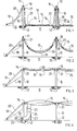
- FIGS 1-4 the process of the invention is illustrated in relation to the erection or installation procedure of the building structure of the invention.
- Support posts 10 are first embedded in the ground 11 by appropriate means such as being embedded :n a concrete block 12.
- a rcof component 13 comprising a pair of opposed gutter members 14 and a roof inflatable membrane 15 interposed between each gutter member 14 is laid on the . ground 11 between a pair of support posts 10.
- Hoisting cables 16 are attached to each gutter member 14 and are attached to pulleys 17 located on the top of support posts 10.
- Support posts 10 are also braced by stays 18.
- There is also shown support cables 19 and 20 for roof components 13 which initially as shown in FIG 1 are in a slack attitude.
- hoisting cables 16 may be pulled through pulleys 17 and thus elevate roof component 13 as shown in FIG 2 until gutter members 14 are mounted on mounting brackets 21. Cables 19 and 20 may also be tensioned by appropriate tensioning means such as a turnbuckle or the like (not shown) until they assume a taut attitude as shown in FIGS 2-3.
- Lift chains 22 may also be used to elevate gutter members 14 to be mounted on mounting brackets 21. Lift chains 22 may be elevated by a crane (not shown) or other suitable elevating means.
- the membrane may be inflated as shown in FIG 4 by appropriate means such as an inflating pipe 23 which may communicate with the interior of membrane 15.
- Inflating pipe 23 may have a control butterfly valve 24 and motor 25 driving impeller 26.
- Inflating pipe 23 may be supported by suitable supports 27.
- FIGS 5-8 the arrangement of posts 10 is illustrated.
- one membrane 15 is utilized between longitudinal rows 28 of support posts 10.
- a plurality (ie. three) membranes are utilized wherein each membrane 15 is located between the series of longitudinal rows 28.
- end peripheral posts 10A located in one end or front of the building structure and clearly the spacing between internal posts 10B is very much greater than between end peripheral posts 10A.
- Peripheral posts l0A are also braced by stays 18 as is the case with side peripheral posts 10C.
- membrane 15 which may comprise an upper membrane 29 and lower membrane 30.
- the side edges of upper membrane 29 and lower membrane 30 may be attached to gutter members 14 and between adjacent gutter members 14 of mutually adjoining membranes there may be provided a gap 32 covered by cover member 33.
- Between adjacent end peripheral posts 10A there may be provided diagonally oriented braces 34 and 35 as shown as well as between corner posts 10 and side peripheral post 10C.
- ground supports 31 in the form of spikes or pegs to which are attached stays 18 as well as support cables 19 and 20.
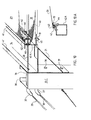
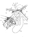
- FIG 10 there is shown rigid pipes 37 for cables 19 and 20 which enable cables 19 and 20 to have a relatively gentle curve or radius before assuming a horizontal orientation as shown.
- Support post 10C is of substantially channel cross sectional shape having slot 36 and return flanges 38.
- Brackets 21 are bolted to support post 10C by bolts 39.
- cables 19 and 20 may have plastics sleeves 40.
- Gutter 14 may have return flanges 41.
- gutters 14 are supported by brackets 21.
- extrusion members 42 of substantially U-shaped cross-section which include a slot or groove 43 for retention of a continuous bead 44 which secures the curtain membrane forming upper membrane 29 and lower membrane 30 in place.
- Bead 44 may secure mutually adjacent side edges of membranes 29 or 30 or alternatively a common strip of membranes 29 or 30 in place in slot 43.
- FIG 10A A detailed view of this arrangement is shown in FIG 10A. Also shown is extrusion support member 42A of substantially rectangular cross section. Also shown is cable clamp 45 and grommet 46.
- FIG 11 there is shown internal post 10B having fixed mounting 47 to footing 12 and bolts 48 attaching mounting 47 to post 10B. Also shown are tabs 49 and 50 attached to gutter members 14. Tabs 49 together with associated apertures 51 are used as attachment locations for pulleys 17 discussed earlier. Tabs 50 together with associated apertures 52 are used for attachment locations for chains 22 discussed earlier.
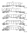
- a rectangular array of posts is formed with two opposed rows of end posts 53 supported in the ground and two adjacent rows of side posts 54 lying on the ground with their tops lying inwardly as shown in FIG 17.
- End posts 53 are supported by cables 55 and 56 which are attached to anchor structure 57 as shown in more detail in FIG 22.
- Side posts 54 are hingedly attached by pivot bolts 59 to a metal plate anchor 58. They also have attached thereto temporary supports 60 acting as a compression column. Supports 60 have cables 61 all attached to winch 62. Also shown is anchor pulley 63. End posts 53 are first erected and attached together by continuous top plate 64. Roof membrane 15 has attached thereto on each side thereof a continuous rigid member 65 in the form of an extrusion which may be clipped to the tops of posts 54 and attached thereto by screws (not shown).
- One cable 66 functions as an upper retaining cable or hold-down cable while the other cable 67 functions as a bottom support cable for roof membrane 15.
- Posts 54 may also be retained in position by braces 68. Subsequently posts 54 may be secured by tightening of bolts 59 in anchor 58. The roof membrane 15 may then be fixed to end plates 64.
- roof membrane 15 may be inflated in similar manner as already described above in FIG 4.
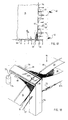
- FIGS 18-22 describes the inflatable building structure formed by the process shown in FIGS 12-17.
- upper and lower membranes 29 and 30 of roof 15 which are each clamped to extrusion 65 by clamping strap 69.
- side curtains 70 and 71 with the bottom curtain 71 functioning as a insect screen.
- Bottom support cables 67 and 67A are also shown as well as turnbuckle tensioner device 72.
- duct 73 interconnecting the interior of membrane 15 and the interior between curtains 70 and 71.
- pump 74 which may communicate with the interior of membrane 15 to inflate same if required through conduit 75.
- a non return valve (not shown) may be associated with the interior of membrane 15 or curtains 70-71 also if required.
- FIG 19 there is shown end post 53, bracing girder 76 and end curtains 77 and 78 with bottom end curtain 77 functioning as an insect screen if desired.
- Top curtain 78 may be rolled up if desired as shown at 79. This may be done mechanically as shown hereinafter in FIG 20 and controlled thermostatically as also shown in FIG 20.
- a conduit (not shown) may communicate between the interior of membrane 15 and the interior of end curtains 77 and 78 as described in FIG 18 in regard to duct 73.
- the pressure maintained within the interior of membrane 15 is between 26-32 pascals.
- FIG 20 there is shown the actuating mechanism for effecting raising or lowering of side curtain 70.
- End curtain 78 may be attached to girder 76 by clamping strap 80.
- Clamping strap 81 may also attach bottom side curtain 77 to girder 68.
- Motor assembly 84 includes motor 85, clutch 86, carrier bracket 87 attached to carriage 83 by bolts 88.
- Pinion 89 attached to output shaft 90 meshes with larger gear wheel 91 and rotates same and therefore mandrel 92 is also rotated.
- Carriage 83 upon actuation of motor 85 moves up and down on carrier rail 82 and to this end has internal roller bearings 93.
- thermostat control 94 attached to support 95 having a rotary control knob 96.
- Power cable 97A interconnects thermostat 94 to motor 85 as shown.
- the mechanism as shown in FIG 20 operates upon actuation of motor 85 by thermostat 94 through solenoid 97.
- motor 85 cuts in solenoid 97 engages clutch 86 and the operation of motor 85 enables carriage 83 to move upwardly or downwardly on carrier rail 82 depending upon the polarity of the power supply.
- FIGS 21-22 there is shown appropriate anchor structure for both the end curtains 77 and 78 and cables 6 6 and 67A.
- anchor post 98 embedded in concrete 99 which optionally comprises a steel RSJ member.
- curtain winch 100 for elevating or lowering end curtain 78.
- lower end curtain 77 There is also shown support cable 101.
- cables 66 and 67A are shown as well as fixed side curtain 71. Also shown are turnbuckles 102 and 103 for tensioning cables 66 and 67A when required. Also shown are galvanized steel stirrups 104, steel reinforcement frame 105 and concrete 106.
- FIG 23 there is shown girder 76, fixed curtain 77, clamping 81, concrete 108 and steel reinforcement frame 109 and bolts 110.
- the inflatable building structure of the invention is very advantageous in use in that the structure is very readily and efficiently installed or erected in comparison with the prior art and also in view of the standard components that may be utilized and is very cost effective.
- the use of the inflatable membrane 15 provides a controlled gutter situation where the membrane 15 in effect functions as a very efficient gutter in case of heavy rainfall and still allows natural light to have access to the greenhouse interior.
- the use of the side curtains and end curtains provides a controlled temperature situation especially where the side curtains and/or end curtains may be selectively raised or lowered as required.
Landscapes
- Engineering & Computer Science (AREA)
- Architecture (AREA)
- Structural Engineering (AREA)
- Physics & Mathematics (AREA)
- Civil Engineering (AREA)
- Electromagnetism (AREA)
- Fluid Mechanics (AREA)
- Life Sciences & Earth Sciences (AREA)
- Environmental Sciences (AREA)
- Tents Or Canopies (AREA)
- Biological Depolymerization Polymers (AREA)
- Buildings Adapted To Withstand Abnormal External Influences (AREA)
- Air Conditioning Control Device (AREA)
- Joining Of Building Structures In Genera (AREA)
- Cultivation Receptacles Or Flower-Pots, Or Pots For Seedlings (AREA)
Priority Applications (1)
| Application Number | Priority Date | Filing Date | Title |
|---|---|---|---|
| AT86303051T ATE62523T1 (de) | 1985-04-24 | 1986-04-23 | Aufblasbares gebaeude. |
Applications Claiming Priority (2)
| Application Number | Priority Date | Filing Date | Title |
|---|---|---|---|
| AUPH029785 | 1985-04-24 | ||
| AU297/85 | 1985-04-24 |
Publications (2)
| Publication Number | Publication Date |
|---|---|
| EP0199592A1 true EP0199592A1 (de) | 1986-10-29 |
| EP0199592B1 EP0199592B1 (de) | 1991-04-10 |
Family
ID=3771071
Family Applications (1)
| Application Number | Title | Priority Date | Filing Date |
|---|---|---|---|
| EP86303051A Expired - Lifetime EP0199592B1 (de) | 1985-04-24 | 1986-04-23 | Aufblasbares Gebäude |
Country Status (8)
| Country | Link |
|---|---|
| US (2) | US4805355A (de) |
| EP (1) | EP0199592B1 (de) |
| AT (1) | ATE62523T1 (de) |
| CA (1) | CA1278731C (de) |
| DE (1) | DE3678604D1 (de) |
| ES (1) | ES8706891A1 (de) |
| MX (1) | MX173698B (de) |
| NZ (1) | NZ215892A (de) |
Cited By (9)
| Publication number | Priority date | Publication date | Assignee | Title |
|---|---|---|---|---|
| GB2207450A (en) * | 1987-07-28 | 1989-02-01 | Malcolm Stuart Gray | Wind break with rain awning |
| US5311699A (en) * | 1991-07-30 | 1994-05-17 | David Huffman | Shade house |
| NL1001501C2 (nl) * | 1995-10-26 | 1997-05-02 | C & J Bosman B V | Draagconstructie voor een foliedek. |
| RU2280744C1 (ru) * | 2005-02-22 | 2006-07-27 | Владимир Владимирович Андрущенко | Павильон |
| GB2425135A (en) * | 2005-11-28 | 2006-10-18 | Christopher Charles Brindle | Support stand for an inflatable tent frame |
| CN105475039A (zh) * | 2015-12-17 | 2016-04-13 | 深圳市中德膜结构有限公司 | 植物采光大棚用气膜拉索网结构 |
| US9366050B1 (en) | 2015-02-03 | 2016-06-14 | Waldemar Ptaszek | Inflatable airship hangar |
| US10551005B2 (en) | 2017-09-06 | 2020-02-04 | Waldemar Ptaszek | Double walled inflatable storage structure |
| US20240301716A1 (en) * | 2023-03-06 | 2024-09-12 | Georgia Tech Research Corporation | System for partially filling an enclosure |
Families Citing this family (32)
| Publication number | Priority date | Publication date | Assignee | Title |
|---|---|---|---|---|
| US5426899A (en) * | 1991-09-27 | 1995-06-27 | Jones; Betty M. R. | Swimming pool cover |
| ES2117529B1 (es) * | 1995-01-27 | 1999-01-01 | Granell Joaquin Tarres | Sistema de cubrimiento y cierre para piscinas y similares. |
| US6282842B1 (en) * | 1995-02-06 | 2001-09-04 | Robert R. Simens | Inflatable roof support systems |
| US5675938A (en) * | 1996-04-23 | 1997-10-14 | Fabric Enclosures, Inc. | Desert envitalization system with variable volume pneumatic polydome enclosure |
| US6000170A (en) * | 1996-07-02 | 1999-12-14 | Davis; Noel | Light energy shutter system |
| FR2760252A1 (fr) * | 1997-03-03 | 1998-09-04 | Rene Ferdinand Albert Ebel | Abri couvert notamment pour agrosysteme |
| US20020022588A1 (en) * | 1998-06-23 | 2002-02-21 | James Wilkie | Methods and compositions for sealing tissue leaks |
| FR2810062B1 (fr) * | 2000-06-08 | 2003-12-05 | Joseph Mercurio | Serre horticole debachable |
| DE10034912A1 (de) * | 2000-07-18 | 2002-02-07 | Marcus Andreas Busler | Transportable Grossbildleinwand |
| NL1018603C2 (nl) * | 2001-07-20 | 2003-01-27 | Naaldhoorn Ii B V | Systeem voor het aanbrengen van een scherm boven een ondergrond. |
| RU2257048C2 (ru) * | 2003-10-01 | 2005-07-27 | Шульгин Николай Борисович | Укрывающий синтетический материал с изменяемыми теплоизоляционными и механическими свойствами |
| US8572911B1 (en) | 2006-02-13 | 2013-11-05 | University Of Akron Research Foundation | Inflatable structure with internal support |
| US20070227083A1 (en) * | 2006-04-03 | 2007-10-04 | Hand Skobba | Hurricane shutters for windows and doors |
| NL2000352C2 (nl) * | 2006-12-04 | 2008-06-06 | Diemen B V Van | Dakconstructie voor een teeltruimte. |
| WO2008069658A1 (en) * | 2006-12-04 | 2008-06-12 | Van Diemen B.V. | Roof construction for a cultivation space |
| US8511365B2 (en) | 2007-04-18 | 2013-08-20 | David McIntosh | Inflatable film production panels |
| US8047257B2 (en) * | 2007-04-18 | 2011-11-01 | Mcintosh David | Inflatable film production panels |
| FR2933182B1 (fr) * | 2008-06-26 | 2010-09-10 | Bachmann Sas | Installation de camouflage |
| US8720125B2 (en) | 2009-07-28 | 2014-05-13 | Micah F. Andretich | Sustainable, mobile, expandable structure |
| US8402704B2 (en) * | 2009-10-27 | 2013-03-26 | Phat Energy Corporation | Solar power structure and kit for making the same |
| US9163401B2 (en) * | 2011-08-04 | 2015-10-20 | Volco Inc. | Retractable roof |
| US20150017897A1 (en) * | 2013-07-10 | 2015-01-15 | Thomas Wiliams | System and Method for Maintaining Airflow within an Inflatable Booth |
| CN103628628A (zh) * | 2013-11-28 | 2014-03-12 | 任进礼 | 温室大棚悬挂式采光遮光索膜装置 |
| WO2016141484A1 (en) * | 2015-03-10 | 2016-09-15 | Paulus Antoine Marcel | Mobile artificial cloud |
| WO2017091699A1 (en) * | 2015-11-23 | 2017-06-01 | Flexible Technologies, Inc. | Insulated duct with air gap and method of use |
| NL2019017B1 (nl) * | 2017-06-02 | 2018-12-11 | Rico Sport & Vastgoed B V | Overkapping voor het selectief overkappen van een oppervlak |
| CN109548530B (zh) * | 2018-12-11 | 2021-11-19 | 徐州徐薯薯业科技有限公司 | 一种蔬菜大棚平移固定装置 |
| CN109386056B (zh) * | 2018-12-19 | 2023-12-08 | 王小建 | 透明屋 |
| US20230091059A1 (en) * | 2019-10-16 | 2023-03-23 | Poseidon Reef Systems LLC | Inflatable grow tent with integrated lighting |
| US12173522B2 (en) | 2020-03-27 | 2024-12-24 | Thomas Williams | Inflatable structure for use in painting aircraft |
| CA3113030A1 (en) | 2020-03-27 | 2021-09-27 | Thomas Williams | Inflatable drive through tunnel system |
| CN115822360A (zh) * | 2022-12-13 | 2023-03-21 | 思迈(青岛)医疗科技有限公司 | 一体化折叠膜舱 |
Citations (4)
| Publication number | Priority date | Publication date | Assignee | Title |
|---|---|---|---|---|
| FR822360A (fr) * | 1936-08-29 | 1937-12-29 | Hangar repliable | |
| US3601944A (en) * | 1969-08-04 | 1971-08-31 | Shepherd Machinery Co | Building frame with cable trusses |
| FR2133006A5 (de) * | 1971-04-05 | 1972-11-24 | Sales Albert | |
| GB1550488A (en) * | 1977-11-10 | 1979-08-15 | Marfani Agricultural Ltd | Inflatable roof for greenhouses |
Family Cites Families (22)
| Publication number | Priority date | Publication date | Assignee | Title |
|---|---|---|---|---|
| US1839076A (en) * | 1928-09-11 | 1931-12-29 | Charles W Adams | Tent |
| US2440557A (en) * | 1945-03-05 | 1948-04-27 | Clifton W Power | Fabric building |
| US2921592A (en) * | 1957-07-10 | 1960-01-19 | Cid Air Structures Company | Support for air-inflated building structure |
| US3113403A (en) * | 1959-04-16 | 1963-12-10 | Cargill Inc | Method of erecting a building |
| US3376879A (en) * | 1963-06-10 | 1968-04-09 | Carl F. Huddle | Portable shelter |
| US3175857A (en) * | 1963-07-31 | 1965-03-30 | Robert E Lewis | Truck camper |
| US3163460A (en) * | 1963-09-09 | 1964-12-29 | Frederic L Cox | Camping trailers |
| GB1049904A (en) * | 1964-05-26 | 1966-11-30 | Frankenstein Group Ltd | Improvements in or relating to collapsible shelters |
| US3338000A (en) * | 1965-04-12 | 1967-08-29 | Ostrander Marian Depew | Inflated roof |
| US3328926A (en) * | 1965-05-06 | 1967-07-04 | Ador Corp | Inflatable housing construction |
| CH485086A (de) * | 1969-05-20 | 1970-01-31 | Hugo Dr Ackermann | Dachkonstruktion für ein Gebäude |
| US3626836A (en) * | 1969-12-04 | 1971-12-14 | Schneidler Ind Inc | Drilling operation shelter |
| US3802450A (en) * | 1970-06-25 | 1974-04-09 | Tension Structures Co | Pavilion with intermediate arch and method of assembling and erecting it |
| US4038788A (en) * | 1973-01-16 | 1977-08-02 | Willem Maria August Claessens | Sliding roof |
| DE2431233A1 (de) * | 1973-07-06 | 1975-01-23 | Stromeyer & Co Gmbh L | Bauwerk |
| US4047335A (en) * | 1975-11-18 | 1977-09-13 | Darmstadt Robert M | Pneumatic load-supporting structures |
| US4297813A (en) * | 1980-01-09 | 1981-11-03 | Cornell Research Foundation, Inc. | Multiple layer insulation cover |
| US4301626A (en) * | 1980-06-09 | 1981-11-24 | Effective Conservation Systems, Inc. | Inflatable heat barrier |
| US4627202A (en) * | 1983-01-04 | 1986-12-09 | Four Seasons Solar Products Corp. | Structural element especially suitable for solar controlling and the like and particularly utilizable for controlling shading |
| US4662146A (en) * | 1983-05-23 | 1987-05-05 | Parry Rodger J | Building frame support and method of erection |
| US4583331A (en) * | 1983-12-27 | 1986-04-22 | Clamshell Partners Ltd. | Frame supported structure with tensioned fabric panels |
| US4590719A (en) * | 1985-02-11 | 1986-05-27 | Mason Corporation | Erection hinge |
-
1986
- 1986-04-21 NZ NZ215892A patent/NZ215892A/xx unknown
- 1986-04-23 ES ES554274A patent/ES8706891A1/es not_active Expired
- 1986-04-23 EP EP86303051A patent/EP0199592B1/de not_active Expired - Lifetime
- 1986-04-23 AT AT86303051T patent/ATE62523T1/de not_active IP Right Cessation
- 1986-04-23 DE DE8686303051T patent/DE3678604D1/de not_active Expired - Fee Related
- 1986-04-24 MX MX002299A patent/MX173698B/es unknown
- 1986-04-24 CA CA000507498A patent/CA1278731C/en not_active Expired - Lifetime
-
1987
- 1987-11-12 US US07/120,164 patent/US4805355A/en not_active Expired - Lifetime
-
1988
- 1988-12-20 US US07/286,737 patent/US4924651A/en not_active Expired - Lifetime
Patent Citations (4)
| Publication number | Priority date | Publication date | Assignee | Title |
|---|---|---|---|---|
| FR822360A (fr) * | 1936-08-29 | 1937-12-29 | Hangar repliable | |
| US3601944A (en) * | 1969-08-04 | 1971-08-31 | Shepherd Machinery Co | Building frame with cable trusses |
| FR2133006A5 (de) * | 1971-04-05 | 1972-11-24 | Sales Albert | |
| GB1550488A (en) * | 1977-11-10 | 1979-08-15 | Marfani Agricultural Ltd | Inflatable roof for greenhouses |
Non-Patent Citations (1)
| Title |
|---|
| BATIR, no. 100, January 1961, pages 26-29; R. BROCARD.: "En guise de toit: un coussin pneumatique" * |
Cited By (12)
| Publication number | Priority date | Publication date | Assignee | Title |
|---|---|---|---|---|
| GB2207450A (en) * | 1987-07-28 | 1989-02-01 | Malcolm Stuart Gray | Wind break with rain awning |
| GB2207450B (en) * | 1987-07-28 | 1991-05-22 | Malcolm Stuart Gray | Wind break apparatus |
| US5311699A (en) * | 1991-07-30 | 1994-05-17 | David Huffman | Shade house |
| NL1001501C2 (nl) * | 1995-10-26 | 1997-05-02 | C & J Bosman B V | Draagconstructie voor een foliedek. |
| RU2280744C1 (ru) * | 2005-02-22 | 2006-07-27 | Владимир Владимирович Андрущенко | Павильон |
| GB2425135A (en) * | 2005-11-28 | 2006-10-18 | Christopher Charles Brindle | Support stand for an inflatable tent frame |
| GB2425135B (en) * | 2005-11-28 | 2007-03-21 | Christopher Charles Brindle | Inflatable structures and support stands therefor |
| US9366050B1 (en) | 2015-02-03 | 2016-06-14 | Waldemar Ptaszek | Inflatable airship hangar |
| CN105475039A (zh) * | 2015-12-17 | 2016-04-13 | 深圳市中德膜结构有限公司 | 植物采光大棚用气膜拉索网结构 |
| CN105475039B (zh) * | 2015-12-17 | 2018-06-19 | 深圳市中德膜结构有限公司 | 植物采光大棚用气膜拉索网结构 |
| US10551005B2 (en) | 2017-09-06 | 2020-02-04 | Waldemar Ptaszek | Double walled inflatable storage structure |
| US20240301716A1 (en) * | 2023-03-06 | 2024-09-12 | Georgia Tech Research Corporation | System for partially filling an enclosure |
Also Published As
| Publication number | Publication date |
|---|---|
| MX173698B (es) | 1994-03-23 |
| DE3678604D1 (de) | 1991-05-16 |
| EP0199592B1 (de) | 1991-04-10 |
| US4924651A (en) | 1990-05-15 |
| NZ215892A (en) | 1989-08-29 |
| ES8706891A1 (es) | 1987-07-01 |
| US4805355A (en) | 1989-02-21 |
| CA1278731C (en) | 1991-01-08 |
| ATE62523T1 (de) | 1991-04-15 |
| ES554274A0 (es) | 1987-07-01 |
Similar Documents
| Publication | Publication Date | Title |
|---|---|---|
| US4805355A (en) | Inflatable building structure | |
| US4381629A (en) | Greenhouse | |
| US5848499A (en) | Cable-stay retractable skylight roof for stadium or arena or other structure and method of construction of same | |
| US3869836A (en) | Mobile home protector | |
| US3765134A (en) | Construction of rigid tensioned frame structure | |
| US3911632A (en) | Gutter structure for holding flexible and non-flexible covers | |
| US5010695A (en) | Cable-stay roof for stadium or arena and method of construction of same | |
| JPS6043090B2 (ja) | 枢着された屋根部を有する温室構造 | |
| EP0795068A1 (de) | Temporäre schutz verkleidung | |
| CN112056127B (zh) | 一种温室边柱组件、温室及温室保温方法 | |
| US5622013A (en) | Structure of multipurpose suspended roof arena capable of changing space volume and construction method thereof | |
| US6223476B1 (en) | Retractable ceiling assembly | |
| US4321775A (en) | Greenhouse construction | |
| AU593796B2 (en) | Inflatable building structure | |
| US5737882A (en) | Apparatus and method for attaching a roof to a building | |
| US4033078A (en) | Housing systems and structures | |
| JP2834386B2 (ja) | 浮上屋根およびその架設方法 | |
| EP0065873A2 (de) | Konstruktionsverfahren | |
| KR101720243B1 (ko) | 갱 폼 일체형 커버링 장치 | |
| JP2764366B2 (ja) | 開閉機構を備えた仮設テント | |
| JP2585174B2 (ja) | 仮設テント用足場の固定方法 | |
| JP2805013B2 (ja) | 仮設屋根構造、仮設壁構造及び仮設足場 | |
| JP2587352Y2 (ja) | 開閉式仮設テント | |
| WO2009073000A1 (en) | Sidewall system for an air supported structure | |
| JPH09250244A (ja) | 仮設屋根構造 |
Legal Events
| Date | Code | Title | Description |
|---|---|---|---|
| PUAI | Public reference made under article 153(3) epc to a published international application that has entered the european phase |
Free format text: ORIGINAL CODE: 0009012 |
|
| AK | Designated contracting states |
Kind code of ref document: A1 Designated state(s): AT BE CH DE FR GB IT LI NL SE |
|
| 17P | Request for examination filed |
Effective date: 19870418 |
|
| 17Q | First examination report despatched |
Effective date: 19880728 |
|
| RAP1 | Party data changed (applicant data changed or rights of an application transferred) |
Owner name: FLEXIPLANT USA |
|
| ITF | It: translation for a ep patent filed | ||
| GRAA | (expected) grant |
Free format text: ORIGINAL CODE: 0009210 |
|
| AK | Designated contracting states |
Kind code of ref document: B1 Designated state(s): AT BE CH DE FR GB IT LI NL SE |
|
| PG25 | Lapsed in a contracting state [announced via postgrant information from national office to epo] |
Ref country code: BE Effective date: 19910410 |
|
| REF | Corresponds to: |
Ref document number: 62523 Country of ref document: AT Date of ref document: 19910415 Kind code of ref document: T |
|
| PG25 | Lapsed in a contracting state [announced via postgrant information from national office to epo] |
Ref country code: AT Effective date: 19910423 |
|
| PG25 | Lapsed in a contracting state [announced via postgrant information from national office to epo] |
Ref country code: SE Effective date: 19910424 |
|
| PG25 | Lapsed in a contracting state [announced via postgrant information from national office to epo] |
Ref country code: LI Effective date: 19910430 Ref country code: CH Effective date: 19910430 |
|
| REF | Corresponds to: |
Ref document number: 3678604 Country of ref document: DE Date of ref document: 19910516 |
|
| ET | Fr: translation filed | ||
| REG | Reference to a national code |
Ref country code: GB Ref legal event code: 732 |
|
| REG | Reference to a national code |
Ref country code: CH Ref legal event code: PL |
|
| PLBE | No opposition filed within time limit |
Free format text: ORIGINAL CODE: 0009261 |
|
| STAA | Information on the status of an ep patent application or granted ep patent |
Free format text: STATUS: NO OPPOSITION FILED WITHIN TIME LIMIT |
|
| ITPR | It: changes in ownership of a european patent |
Owner name: CESSIONE;STEPHEN WILLIAM BROWN |
|
| NLS | Nl: assignments of ep-patents |
Owner name: STEPHEN WILLIAM BROWN TE CARSELDINO, AUSTRALIE. |
|
| 26N | No opposition filed | ||
| REG | Reference to a national code |
Ref country code: FR Ref legal event code: TP |
|
| EUG | Se: european patent has lapsed |
Ref document number: 86303051.6 Effective date: 19920109 |
|
| PGFP | Annual fee paid to national office [announced via postgrant information from national office to epo] |
Ref country code: GB Payment date: 19971008 Year of fee payment: 12 |
|
| PGFP | Annual fee paid to national office [announced via postgrant information from national office to epo] |
Ref country code: NL Payment date: 19971010 Year of fee payment: 12 |
|
| PGFP | Annual fee paid to national office [announced via postgrant information from national office to epo] |
Ref country code: FR Payment date: 19971014 Year of fee payment: 12 |
|
| PGFP | Annual fee paid to national office [announced via postgrant information from national office to epo] |
Ref country code: DE Payment date: 19971020 Year of fee payment: 12 |
|
| PG25 | Lapsed in a contracting state [announced via postgrant information from national office to epo] |
Ref country code: GB Free format text: LAPSE BECAUSE OF NON-PAYMENT OF DUE FEES Effective date: 19980423 |
|
| PG25 | Lapsed in a contracting state [announced via postgrant information from national office to epo] |
Ref country code: FR Free format text: THE PATENT HAS BEEN ANNULLED BY A DECISION OF A NATIONAL AUTHORITY Effective date: 19980430 |
|
| PG25 | Lapsed in a contracting state [announced via postgrant information from national office to epo] |
Ref country code: NL Free format text: LAPSE BECAUSE OF NON-PAYMENT OF DUE FEES Effective date: 19981101 |
|
| GBPC | Gb: european patent ceased through non-payment of renewal fee |
Effective date: 19980423 |
|
| NLV4 | Nl: lapsed or anulled due to non-payment of the annual fee |
Effective date: 19981101 |
|
| PG25 | Lapsed in a contracting state [announced via postgrant information from national office to epo] |
Ref country code: DE Free format text: LAPSE BECAUSE OF NON-PAYMENT OF DUE FEES Effective date: 19990202 |
|
| REG | Reference to a national code |
Ref country code: FR Ref legal event code: ST |
|
| PG25 | Lapsed in a contracting state [announced via postgrant information from national office to epo] |
Ref country code: IT Free format text: LAPSE BECAUSE OF NON-PAYMENT OF DUE FEES;WARNING: LAPSES OF ITALIAN PATENTS WITH EFFECTIVE DATE BEFORE 2007 MAY HAVE OCCURRED AT ANY TIME BEFORE 2007. THE CORRECT EFFECTIVE DATE MAY BE DIFFERENT FROM THE ONE RECORDED. Effective date: 20050423 |