EP0199610A2 - Vorrichtung zum Reduzieren der Totzeit bei Analysegeräten, insbesondere bei der thermogravimetrischen Analyse - Google Patents
Vorrichtung zum Reduzieren der Totzeit bei Analysegeräten, insbesondere bei der thermogravimetrischen Analyse Download PDFInfo
- Publication number
- EP0199610A2 EP0199610A2 EP86400455A EP86400455A EP0199610A2 EP 0199610 A2 EP0199610 A2 EP 0199610A2 EP 86400455 A EP86400455 A EP 86400455A EP 86400455 A EP86400455 A EP 86400455A EP 0199610 A2 EP0199610 A2 EP 0199610A2
- Authority
- EP
- European Patent Office
- Prior art keywords
- suspension
- analysis apparatus
- thermobalance
- sample
- analysis
- Prior art date
- Legal status (The legal status is an assumption and is not a legal conclusion. Google has not performed a legal analysis and makes no representation as to the accuracy of the status listed.)
- Withdrawn
Links
Images

Classifications
-
- G—PHYSICS
- G01—MEASURING; TESTING
- G01N—INVESTIGATING OR ANALYSING MATERIALS BY DETERMINING THEIR CHEMICAL OR PHYSICAL PROPERTIES
- G01N5/00—Analysing materials by weighing, e.g. weighing small particles separated from a gas or liquid
Definitions
- the present invention relates to an analysis apparatus, in particular thermogravimetric analysis, comprising an analysis enclosure, such as an oven, inside which a sample to be analyzed is intended to be immersed therein. be maintained in a measurement position, and a measurement instrument, in particular a thermobalance, capable of determining the value of a physical characteristic of the sample placed in said measurement position.
- an analysis apparatus in particular thermogravimetric analysis, comprising an analysis enclosure, such as an oven, inside which a sample to be analyzed is intended to be immersed therein. be maintained in a measurement position, and a measurement instrument, in particular a thermobalance, capable of determining the value of a physical characteristic of the sample placed in said measurement position.
- Devices of this type are used to analyze the physico-chemical properties of a sample as a function of one or more factors, such as, for example, temperature.
- thermogravimetric analyzes carried out in an isothermal manner using these devices, an inaccuracy is inevitably introduced into the results by "zero time", which is the time necessary for the sample to go from a given temperature to the temperature required by the analysis.
- thermogravimetric analyzes it is also known that this technique does not allow the sample to be introduced and removed at will from the analysis medium.
- the present invention proposes to remedy this drawback by producing an analysis apparatus of the type specified in the preamble, which makes it possible to reduce and fix precisely the zero time and which, for this purpose, is characterized in that '' It comprises a suspension provided with a nacelle for supporting the sample to be analyzed, as well as a zero time reduction device comprising retaining means capable, in a first position, of keeping said suspension outside of the analysis enclosure and control means capable of placing the retaining means in a second position, to allow the suspension to drop instantly in the enclosure. a fastening member being further provided for immobilizing the suspension at a point corresponding to said position for measuring the sample.
- the sample is instantly immersed in the analysis medium, and in particular the thermal medium, which cancels the analysis fluctuations due to the slow change in temperature setting.
- the present invention allows a saving of reagent and time while eliminating the risks of toxicity due to the use of aggressive gases.
- said retaining means comprise a support arm supporting said suspension and said control means are constituted by a drive mechanism capable of moving the support arm, between two points fixing said first and second positions.
- said drive mechanism comprises a vertical threaded rod onto which is screwed a nut integral with the support arm and which is coupled to a motor, as well as a guigant rod parallel to and along the threaded rod. which the support arm is slidably mounted.
- This first embodiment of the invention allows not only to immediately immerse the sample in the analysis medium, but also to move it at will in the latter, which allows a multiplicity of analyzes on the same sample, such as successive quenchings, modifications of the operating conditions at different rates of progress of the transformation studied ... etc.
- the engine is controlled by a computer which makes it possible to automate the above-mentioned sequence of analyzes.
- the support arm supports the suspension by a hook engaged, in a separable manner, in a ring carried by the upper end of the suspension.
- the first embodiment of the zero time reduction device is particularly well suited for equipping analysis apparatuses equipped with a flail thermobalance.
- the attachment member of the suspension carrying the sample to be analyzed will advantageously be constituted by a ring formed at one end of the flail of the thermobalance and having a part in a tapered downward point in which is intended to engage a hook provided on the suspension.
- a retractable double stop is arranged on either side of the ring of the thermobalance beam to dampen the latter's oscillations, when the suspension is attached, this double stop being then removed from the field of displacement of the beam to allow weighing.
- the first embodiment of the zero time reduction device in accordance with the invention, can equally well equip an analysis apparatus provided with a spring thermobalance, such as a thermobalance of the Mac Bain and Bakr type. .
- thermobalance for this type of thermobalance, however, a second embodiment of the zero time reduction device according to the invention can be used as a variant, the retaining means of which comprise two flexible blades which, in their first position, are kept in mutual contact in a vertical plane by enclosing between them the suspension and the control means of which are constituted by a spreading mechanism capable of exerting a horizontal thrust on the flexible blades to separate them from one another and thus place them in their second position, in which the suspension instantly drops into the analysis chamber, to place the sample in its measurement position.
- said spacing mechanism comprises a smooth horizontal rod which, at one end, is fixed to the two flexible blades and, by its second end, is slidably mounted inside a fixed sleeve carrying an external thread on which is screwed a nut that leans against a shoulder of the smooth rod.
- the attachment member of the suspension carrying the sample to be analyzed will advantageously consist of a thin tube secured to the lower end of the thermobalance spring and traversed by the suspension, which carries a protuberance capable of being applied against the upper end of the tube.
- the thin tube carries the thermobalance detection cover, which is arranged, with a limited possibility of movement, between four stops, to prevent any oscillation of the suspension when it is hooked and to avoid excessive retraction of the thermobalance spring. after lifting the suspension by hand.
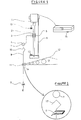
- the zero time reduction device associated with a flail thermobalance, consists of a direct current electric motor 1 coupled to a vertical threaded rod 2 which drives in its rotation a nut 3 of the same pitch provided with a hook 4 and a support arm 5.
- the arm 5 by sliding along a guide rod 6 prevents the nut 3 from turning on it -even.
- the hook 4, by engaging in a ring 7 of the suspension 8 can raise or lower at will the sample E retained in a nacelle 9.
- the suspension 8 always takes the same position on the end 11 of the beam 12 , each time that a weighing is carried out, it can be given in the form of a tapered ring pointing downwards into which the suspension 8 passes and hangs by a hook 10 (see FIG. 2) .
- judiciously placed limit switches 13 make it possible to stop the motor 1 when the sample 9 is completely raised or when the hook 4 is completely disconnected from the ring 7 of the suspension 8 in the event of weighing.
- a retractable double stop 14 blocks the beam 12 so as to release it only when the hook 10 rests perfectly on the end 11 of the beam 12. All of the operations for reducing zero time, as well as those of the stops 14 can be controlled and synchronized by a computer 15.
- This reduction device can be adapted to all known flail thermobalances, provided that it is given an adequate position for each type of thermobalance.
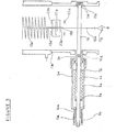
- the zero time reduction device associated with a spring thermobalance of the Mac Bain and Bakr type, consists of two thin steel blades 1a which are fixed, of a firstly, to a thread 2a and, secondly, to the head 3a of a smooth rod 4a which is linked to a cylindrical body 5a by a bellows 6a welded at 7a and 8a.
- the smooth rod 4a can slide in its movement guide, thanks to a connecting nut 13a which pushes it at its end 9a, which is provided with a shoulder.
- the body 5a is connected to a wall 10a of the sheath 11a of the spring 12a.
- the sliding of the rod 4a is obtained by a movement of the screw-nut 13a-14a which results in a separation of the two flexible blades 1a since the threaded end 2a is engaged in the opposite wall 15a which serves as a stop.
- the flexible blades 1a by deviating at will allow the suspension 16a to bring the sample E, retained in a nacelle 17a, from one point to another from top to bottom, in an irreversible manner, progressive or not in a medium of given conditions.
- the suspension 16a is lifted by hand before being pinched by the flexible blades 1a.
- a thin tube 20a is welded at its lower end 19a which carries the detection cover 21a and allows the suspension 16a to pass through its hole 18a.
- the cover placed between four stops 22a, prevents the spring 12a from contracting when the suspension 16a is raised.
- the zero time reduction device associated with a spring thermobalance of the Mac Bain and Bakr type, is of the same type as that which was applied to the flail thermobalance (FIG. 1) with his computer 15 previously described.
- a quartz hook 4 crosses the spring 10b over its entire length to take the suspension 8 by its upper end 7 in order to raise or lower at will the sample E retained in the nacelle 9.
- the zero time reduction device object of the invention, can be fully or partially automated. It finds its application in all cases where it is a question of withdrawing or introducing a sample into a medium of physicochemical nature given at a desired time and can be associated with any type of thermobalance, such as flail thermobalances , spring or magnetic suspension.
- the zero time reduction device according to the invention can be controlled by a computer which also serves to process the analysis data according to a previously established program.
Landscapes
- Physics & Mathematics (AREA)
- Health & Medical Sciences (AREA)
- Life Sciences & Earth Sciences (AREA)
- Chemical & Material Sciences (AREA)
- Analytical Chemistry (AREA)
- Biochemistry (AREA)
- General Health & Medical Sciences (AREA)
- General Physics & Mathematics (AREA)
- Immunology (AREA)
- Pathology (AREA)
- Investigating Or Analyzing Materials Using Thermal Means (AREA)
Applications Claiming Priority (2)
| Application Number | Priority Date | Filing Date | Title |
|---|---|---|---|
| MA20633 | 1985-04-15 | ||
| MA20633A MA20409A1 (fr) | 1985-04-15 | 1985-04-15 | Un reducteur du temps zero pour les appareils d'analyse |
Publications (2)
| Publication Number | Publication Date |
|---|---|
| EP0199610A2 true EP0199610A2 (de) | 1986-10-29 |
| EP0199610A3 EP0199610A3 (de) | 1988-03-02 |
Family
ID=32292259
Family Applications (1)
| Application Number | Title | Priority Date | Filing Date |
|---|---|---|---|
| EP86400455A Withdrawn EP0199610A3 (de) | 1985-04-15 | 1986-03-05 | Vorrichtung zum Reduzieren der Totzeit bei Analysegeräten, insbesondere bei der thermogravimetrischen Analyse |
Country Status (2)
| Country | Link |
|---|---|
| EP (1) | EP0199610A3 (de) |
| MA (1) | MA20409A1 (de) |
Cited By (1)
| Publication number | Priority date | Publication date | Assignee | Title |
|---|---|---|---|---|
| CN102809418A (zh) * | 2012-08-03 | 2012-12-05 | 昆山旭虹精密零组件有限公司 | 一种高温加热天平 |
Family Cites Families (3)
| Publication number | Priority date | Publication date | Assignee | Title |
|---|---|---|---|---|
| US3055206A (en) * | 1958-08-14 | 1962-09-25 | American Instr Co Inc | Apparatus for measuring changes in weight of samples as a function of temperature |
| FR1505410A (fr) * | 1966-08-04 | 1967-12-15 | Centre Nat Rech Scient | Perfectionnements apportés aux moyens pour la détermination des masses spécifiques des solides |
| GB1443789A (en) * | 1973-11-28 | 1976-07-28 | Monsanto Ltd | Apparatus for measuring specific gravity |
-
1985
- 1985-04-15 MA MA20633A patent/MA20409A1/fr unknown
-
1986
- 1986-03-05 EP EP86400455A patent/EP0199610A3/de not_active Withdrawn
Cited By (1)
| Publication number | Priority date | Publication date | Assignee | Title |
|---|---|---|---|---|
| CN102809418A (zh) * | 2012-08-03 | 2012-12-05 | 昆山旭虹精密零组件有限公司 | 一种高温加热天平 |
Also Published As
| Publication number | Publication date |
|---|---|
| MA20409A1 (fr) | 1985-12-31 |
| EP0199610A3 (de) | 1988-03-02 |
Similar Documents
| Publication | Publication Date | Title |
|---|---|---|
| EP0767375B1 (de) | Verfahren und Vorrichtung zur Bestimmung der petrologischen Eigenschaften von Schichtgesteinen | |
| US7377189B2 (en) | Sampling device and method for an automatic analyser | |
| FR2527221A1 (fr) | Appareil automatique pour le transfert de colonies bacteriennes | |
| EP0036801A1 (de) | Gerät zur automatischen Messung der Viskosität von Flüssigkeiten | |
| EP0018905B1 (de) | Vorrichtung zur Messung der Koagulations- oder Lyse-Parameter | |
| EP2219036B1 (de) | Multifunktionsrastersondenmikroskop | |
| EP0199610A2 (de) | Vorrichtung zum Reduzieren der Totzeit bei Analysegeräten, insbesondere bei der thermogravimetrischen Analyse | |
| EP1666582B1 (de) | Vorrichtung zur Entnahme von Kernproben für Gewebe-Array | |
| FR2569479A1 (fr) | Appareil de traitement d'echantillons, notamment d'echantillons de tissus | |
| JPH0618534A (ja) | 分注装置用ピペッティングチップ取り外し装置 | |
| Sing | Direct sample insertion for inductively coupled plasma spectrometry | |
| US6840668B1 (en) | Thermogravimetrical analyzer autosampler sealed sample pan | |
| GB2072145A (en) | Liquid core sampler | |
| EP0246940B1 (de) | Verfahren und Vorrichtung zum Regeln der Unterkühlung der Erstarrungsfront eines Einkristalls während des Wachsens und Anwendung dieser Einkristallregelung | |
| FR2516647A1 (fr) | Procede et appareil pour le controle automatique et le dressage de cadres de bicyclettes | |
| FR2695207A1 (fr) | Installation pour mesurer la déformation in situ de chapelets d'éprouvettes soumis à des essais de fluage de longue durée. | |
| FR2505703A1 (fr) | Outil d'extraction et d'insertion de boulons de differentes longueurs | |
| US4852414A (en) | Device for inserting and removing the sample in an analysis oven | |
| CH366404A (fr) | Procédé de remplissage à un même poids net de récipients ayant des tares différentes et dispositif pour la mise en oeuvre de ce procédé | |
| EP0117182B1 (de) | Vorrichtung zur Blutanalyse und Verfahren zu deren Bedienung | |
| CH405761A (fr) | Scléromètre | |
| EP0433108B1 (de) | Verfahren und Vorrichtung zur Anordnung einer Probe in einem Ofen und Ofen mit solcher Vorrichtung | |
| EP0310494A2 (de) | Verfahren zur Steuerung eines Einkristallziehungsapparates | |
| JP2001281116A (ja) | 液状物質サンプリング装置 | |
| WO2004109296A1 (fr) | Procede et dispositif de mise en place d’un recipient dans un dispositif de prelevement de liquide |
Legal Events
| Date | Code | Title | Description |
|---|---|---|---|
| PUAI | Public reference made under article 153(3) epc to a published international application that has entered the european phase |
Free format text: ORIGINAL CODE: 0009012 |
|
| AK | Designated contracting states |
Kind code of ref document: A2 Designated state(s): BE CH DE FR GB IT LI LU SE |
|
| PUAL | Search report despatched |
Free format text: ORIGINAL CODE: 0009013 |
|
| AK | Designated contracting states |
Kind code of ref document: A3 Designated state(s): BE CH DE FR GB IT LI LU SE |
|
| STAA | Information on the status of an ep patent application or granted ep patent |
Free format text: STATUS: THE APPLICATION IS DEEMED TO BE WITHDRAWN |
|
| 18D | Application deemed to be withdrawn |
Effective date: 19881001 |
|
| RIN1 | Information on inventor provided before grant (corrected) |
Inventor name: LARBI, BELKBIR |