EP0199626A1 - Verfahren und Gerät zur Verkehrsbeschränkung in einem Abfrage-/Antwortsystem vom Typ Sekundär-Radar oder IFF-System - Google Patents
Verfahren und Gerät zur Verkehrsbeschränkung in einem Abfrage-/Antwortsystem vom Typ Sekundär-Radar oder IFF-System Download PDFInfo
- Publication number
- EP0199626A1 EP0199626A1 EP86400740A EP86400740A EP0199626A1 EP 0199626 A1 EP0199626 A1 EP 0199626A1 EP 86400740 A EP86400740 A EP 86400740A EP 86400740 A EP86400740 A EP 86400740A EP 0199626 A1 EP0199626 A1 EP 0199626A1
- Authority
- EP
- European Patent Office
- Prior art keywords
- output
- memory
- interrogations
- comparator
- input
- Prior art date
- Legal status (The legal status is an assumption and is not a legal conclusion. Google has not performed a legal analysis and makes no representation as to the accuracy of the status listed.)
- Granted
Links
Images


Classifications
-
- G—PHYSICS
- G08—SIGNALLING
- G08G—TRAFFIC CONTROL SYSTEMS
- G08G1/00—Traffic control systems for road vehicles
-
- G—PHYSICS
- G01—MEASURING; TESTING
- G01S—RADIO DIRECTION-FINDING; RADIO NAVIGATION; DETERMINING DISTANCE OR VELOCITY BY USE OF RADIO WAVES; LOCATING OR PRESENCE-DETECTING BY USE OF THE REFLECTION OR RERADIATION OF RADIO WAVES; ANALOGOUS ARRANGEMENTS USING OTHER WAVES
- G01S13/00—Systems using the reflection or reradiation of radio waves, e.g. radar systems; Analogous systems using reflection or reradiation of waves whose nature or wavelength is irrelevant or unspecified
- G01S13/74—Systems using reradiation of radio waves, e.g. secondary radar systems; Analogous systems
- G01S13/76—Systems using reradiation of radio waves, e.g. secondary radar systems; Analogous systems wherein pulse-type signals are transmitted
- G01S13/767—Responders; Transponders
-
- G—PHYSICS
- G01—MEASURING; TESTING
- G01S—RADIO DIRECTION-FINDING; RADIO NAVIGATION; DETERMINING DISTANCE OR VELOCITY BY USE OF RADIO WAVES; LOCATING OR PRESENCE-DETECTING BY USE OF THE REFLECTION OR RERADIATION OF RADIO WAVES; ANALOGOUS ARRANGEMENTS USING OTHER WAVES
- G01S13/00—Systems using the reflection or reradiation of radio waves, e.g. radar systems; Analogous systems using reflection or reradiation of waves whose nature or wavelength is irrelevant or unspecified
- G01S13/74—Systems using reradiation of radio waves, e.g. secondary radar systems; Analogous systems
- G01S13/76—Systems using reradiation of radio waves, e.g. secondary radar systems; Analogous systems wherein pulse-type signals are transmitted
- G01S13/78—Systems using reradiation of radio waves, e.g. secondary radar systems; Analogous systems wherein pulse-type signals are transmitted discriminating between different kinds of targets, e.g. IFF-radar, i.e. identification of friend or foe
- G01S13/781—Secondary Surveillance Radar [SSR] in general
Definitions
- the present invention relates to a method and to a device for limiting traffic for interrogator / answering system such as a secondary radar or IFF system.
- a mobile platform carrying a transponder can be interrogated at the same time by a certain number of interrogators based on the ground or on other platforms. If the number of interrogations occurring in a short period of time is too large, they lose their intelligibility by mutual interference, and too many responses overload the transmitter of the transponder. According to the prior art, this problem is solved by desensitizing the transponder receiver by means analogous to automatic gain control, so as to eliminate interrogations according to a reception level criterion, the weakest being supposed to come from interrogators the more distant, therefore the least concerned by the presence of the mobile platform in their surveillance sector.
- the subject of the present invention is a method and a device for limiting traffic, limiting this traffic only during peak periods.
- the traffic limitation method according to the invention consists in limiting the number of interrogations taken into account according to criteria of temporal statistical distribution. This limitation consists in periodically comparing the number of interrogations occurring during a time interval of determined duration with a limit value, and in blocking the incidental interrogations as soon as this limit is reached, until the next comparison.
- the device for implementing the method of the invention comprises an input gate with AND function, receiving on one of its inputs pulses representative of the interrogations, the output of this gate being connected on the one hand to an output of authorization to take into account interrogations, and on the other hand to a counter whose output is connected on the one hand to an adder connected moreover to a memory storing at least one criterion value, and on the other hand to a first input of a comparator, the output of the adder being connected to a device for memorizing at least one set value, the output of which is connected to a second input of said comparator, the output of this comparator being connected via a storage device at a second input of said AND gate.
- the traffic limitation device shown in FIG. 1 receives on its input terminal 1 pulses each corresponding to an interrogation arriving at the transponder (not shown) in which the device of the invention is housed.
- This transponder is part of an interrogation / response system such as a secondary radar or an IFF system.
- Terminal 1 is connected to a first input of an AND gate referenced 2.
- the output of door 2 is connected to an output terminal 3 and to the counting input of a counter 4.
- On terminal 3 appear the validation signals produced by the device of the invention, as explained below, these signals authorizing the transponder to accept the requests of the interrogators concerned. It is however understood that one could just as easily produce an inhibition signal on terminal 3, by inserting an inverter just upstream.
- the output of the counter 4 is connected on the one hand to a first input of an adder 5, and on the other hand to a first input of a comparator 6.
- the second input of the adder 5 is connected to the output d 'a memory circuit 7, which can be, in the simplest case, a register.
- This circuit 7 contains at least one value K T , or criterion, representing the maximum number of incident pulses (on terminal 1) generated during any time interval Ti of duration T.
- the output of the adder 5 is connected to a memory circuit 8 memorizing at least one set value V c .
- circuit 8 can be a register.
- the output of circuit 8 is connected to the second input of comparator 6.
- circuit 9 is a flip-flop.
- the inverted output of circuit 9 is connected to the second input of door 2.
- Incident pulses are transmitted to output 3 as long as door 2 is not blocked. Each pulse thus transmitted increments counter 4 by one unit.
- the counter 4 is found, due to the counts earlier than an initial value Nt.
- V Nt + K ⁇ obtained by adding by the circuit 5 the content of the counter 4 and the memory 7. This quantity will serve as a set value until the end of the interval Ti .
- we compare in 6 we compare in 6, with a periodicity t the state of the counter 4 to the content of the memory 8. If we reach equality, the output signal of the comparator 6 changes state logic.
- Memory 9 stores this event and sends a blocking signal to door 2.
- the only condition required so that the counter 4 cannot exceed the set value is that one chooses the value of t - (periodicity of the comparison in 6) sufficiently small so that it cannot occur there more with a single incident pulse. It is also possible to process the incident signal (just upstream of input 1) using a logic circuit making it possible to mask all the pulses subsequent to the first in each period. Such a circuit is obvious to realize for the 'skilled' in the art, and will not be described in detail.
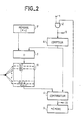
- the circuit shown in FIG. 2 is an improvement on that of FIG. 1.
- the results obtained can depend on the original instant chosen for the comb of the time intervals Ti.
- a peak in temporal density of the incident pulses can be masked as a result of its sharing between two consecutive time intervals Tj, Tj + 1.
- the embodiment shown in FIG. 2 is used.
- a memory 10 replaces the register 8 of the circuit of FIG. 1.
- the state of counter 4 is compared with the set value VCi (that is to say one of the n set values VC o to VC n-1 of memory 10), corresponding to box i. Then, the content of box i is updated with the value Ni + K T , Ni being the state of counter 4 at the end of time ti.
- the reference time intervals of the consecutive memory cells are offset by t.
- a memory 10 with a capacity of 64 bytes is used as memory 10.
- the circuit of FIG. 3 represents a first generalization of that of FIG. 2 making it possible to implement the function of the circuit of FIG. 2 for a plurality of reference time intervals T associated with a plurality of values K T.
- the number of reference time intervals namely T1 and T2
- T1 and T2 has been limited to two, but it is understood that their number may be much greater.
- K1 and K2 With these two time intervals, two values K T are associated, namely K1 and K2, with K2> K1.
- the values K1 and K2 are stored in a criteria memory 11. Because one must store, in the present case, two sets of setpoints corresponding to the two criteria (T1, K1) and (T2, K2), a memory 12 with larger setpoints than previously is used.
- This memory 12 comprises two storage sets 13, 14 respectively storing the n1 and n2 sets of setpoints (Vc'o to Vc ' n1-1 ) and (Vc "o to Vc" n2-1 ).
- these two storage sets are not necessarily distinct: one memory circuit can be used, the addressing of which is controlled so as to obtain, at any instant of addressing, a set value in each of these two sets of values.
- the circuit of FIG. 3 operates in time multiplex, the two sets of setpoints being addressed alternately.
- the elementary time t must be a common divisor of T1 and T2.
- the number of memory "boxes" required for memory 12 is
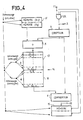
- the invention provides that it is not necessary to update the setpoint values of the criterion as often (T2, K2) than those corresponding to the criterion (T1, K1).
- the circuit of FIG. 4 is then used, in which, with respect to that of FIG. 3, a memory 16 of set values is used in place of the memory 12.
- the tests of criteria (T1, K1) and (T2, K2) are carried out at each time interval t.
- the same address (memory box) is tested and updated after a time T1, c 'ie after each series of n1 elementary times t.
- the counting by the counter 4 and the presentation of the incident pulses on the output 3 are stopped as soon as any of the setpoint values in force is exceeded.
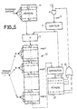
- FIG. 5 shows the most general case of the circuit of the invention.
- the setpoint memory 20 includes p storage sets (or "pages") in each of which are stored the setpoints corresponding to each of the Q criteria.
- the comparator 6 is followed by a memory 21 with p memory boxes each connected to one of the Q inputs of a NOR gate 22, the output of which is connected to the second input of gate 2.
- the variant of the circuit of the invention shown in FIG. 6 differs from the other embodiments described above in that the input of the memory 8 is only connected to the counter 4, the adder 5 being connected at the outputs of memory 8 and memory 7.
- memory 8 is updated with the current value of counter 4, the addition with the constant Ki which provides the set value V ci taking place just before each comparison in the comparator 6.
- this variant can be used in any of the embodiments of FIGS. 1 to 5.
- the crossing of one of the criteria results in a change in logic level at the output 23 of the comparator 6.
- a circuit providing a voltage proportional to the frequency of these crossings can be used to generate the AGC control voltage.
- Such a circuit is well known to those skilled in the art and will not be described in detail.
Landscapes
- Engineering & Computer Science (AREA)
- Radar, Positioning & Navigation (AREA)
- Remote Sensing (AREA)
- Physics & Mathematics (AREA)
- General Physics & Mathematics (AREA)
- Computer Networks & Wireless Communication (AREA)
- Radar Systems Or Details Thereof (AREA)
Applications Claiming Priority (2)
| Application Number | Priority Date | Filing Date | Title |
|---|---|---|---|
| FR8505335A FR2580081B1 (de) | 1985-04-09 | 1985-04-09 | |
| FR8505335 | 1985-04-09 |
Publications (2)
| Publication Number | Publication Date |
|---|---|
| EP0199626A1 true EP0199626A1 (de) | 1986-10-29 |
| EP0199626B1 EP0199626B1 (de) | 1990-05-23 |
Family
ID=9318066
Family Applications (1)
| Application Number | Title | Priority Date | Filing Date |
|---|---|---|---|
| EP86400740A Expired - Lifetime EP0199626B1 (de) | 1985-04-09 | 1986-04-07 | Verfahren und Gerät zur Verkehrsbeschränkung in einem Abfrage-/Antwortsystem vom Typ Sekundär-Radar oder IFF-System |
Country Status (8)
| Country | Link |
|---|---|
| US (1) | US4779096A (de) |
| EP (1) | EP0199626B1 (de) |
| JP (1) | JPS61247987A (de) |
| KR (1) | KR860008520A (de) |
| CA (1) | CA1257369A (de) |
| DE (1) | DE3671537D1 (de) |
| FR (1) | FR2580081B1 (de) |
| IL (1) | IL78406A0 (de) |
Cited By (1)
| Publication number | Priority date | Publication date | Assignee | Title |
|---|---|---|---|---|
| EP0351598A3 (en) * | 1988-06-30 | 1990-02-28 | Honeywell Inc. | Arrangement for reply rate limiting |
Citations (3)
| Publication number | Priority date | Publication date | Assignee | Title |
|---|---|---|---|---|
| US2923935A (en) * | 1960-02-02 | Protective system for radio beacons | ||
| US3875570A (en) * | 1973-03-27 | 1975-04-01 | Litchstreet Co | Adaptive proximity indicating system |
| FR2407487A1 (fr) * | 1977-10-26 | 1979-05-25 | Dassault Electronique | Procede pour faciliter l'exploitation a un aerodrome de messages radar de reponse recus a partir d'avions et installation pour la mise en oeuvre de ce procede |
Family Cites Families (2)
| Publication number | Priority date | Publication date | Assignee | Title |
|---|---|---|---|---|
| US4067011A (en) * | 1976-10-22 | 1978-01-03 | Motorola, Inc. | Digital transponder universal pulse assembly |
| JPS58129278A (ja) * | 1982-01-28 | 1983-08-02 | Nec Corp | ガ−ブル検知装置 |
-
1985
- 1985-04-09 FR FR8505335A patent/FR2580081B1/fr not_active Expired
-
1986
- 1986-04-02 IL IL78406A patent/IL78406A0/xx not_active IP Right Cessation
- 1986-04-07 EP EP86400740A patent/EP0199626B1/de not_active Expired - Lifetime
- 1986-04-07 DE DE8686400740T patent/DE3671537D1/de not_active Expired - Fee Related
- 1986-04-07 US US06/848,568 patent/US4779096A/en not_active Expired - Fee Related
- 1986-04-08 CA CA000506057A patent/CA1257369A/fr not_active Expired
- 1986-04-08 KR KR1019860002644A patent/KR860008520A/ko not_active Ceased
- 1986-04-09 JP JP61081973A patent/JPS61247987A/ja active Pending
Patent Citations (3)
| Publication number | Priority date | Publication date | Assignee | Title |
|---|---|---|---|---|
| US2923935A (en) * | 1960-02-02 | Protective system for radio beacons | ||
| US3875570A (en) * | 1973-03-27 | 1975-04-01 | Litchstreet Co | Adaptive proximity indicating system |
| FR2407487A1 (fr) * | 1977-10-26 | 1979-05-25 | Dassault Electronique | Procede pour faciliter l'exploitation a un aerodrome de messages radar de reponse recus a partir d'avions et installation pour la mise en oeuvre de ce procede |
Cited By (1)
| Publication number | Priority date | Publication date | Assignee | Title |
|---|---|---|---|---|
| EP0351598A3 (en) * | 1988-06-30 | 1990-02-28 | Honeywell Inc. | Arrangement for reply rate limiting |
Also Published As
| Publication number | Publication date |
|---|---|
| CA1257369A (fr) | 1989-07-11 |
| EP0199626B1 (de) | 1990-05-23 |
| JPS61247987A (ja) | 1986-11-05 |
| DE3671537D1 (de) | 1990-06-28 |
| IL78406A0 (en) | 1986-08-31 |
| FR2580081A1 (de) | 1986-10-10 |
| FR2580081B1 (de) | 1988-06-24 |
| US4779096A (en) | 1988-10-18 |
| KR860008520A (ko) | 1986-11-15 |
Similar Documents
| Publication | Publication Date | Title |
|---|---|---|
| EP0006779B1 (de) | Schaltung zur Digitalisierung von einmalig auftretenden Signalen | |
| EP0675345B1 (de) | Einrichtung und Verfahren zum Lichtempfang, mit Verwendung in einem CCD-Bildsensor oder ähnlichem | |
| EP0425356A1 (de) | Verfahren und Vorrichtung zur Zielerkennung | |
| AU2002323371B2 (en) | Apparatus and a method for pulse detection and characterization | |
| EP0107996A1 (de) | Elektronischer Zähler zum Messen von aktiver und reaktiver Energie in einem Dreiphasennetz | |
| EP0094279A1 (de) | Verfahren zum Schutz eines Fernüberwachungssystemes gegen Sabotage und System zur Ausführung dieses Verfahrens | |
| EP0577478B1 (de) | Verfahren und Vorrichtung zum Filtern der Antworten in einem Sekundärradarextraktor | |
| FR2535552A1 (fr) | Appareil et procede pour la synthese d'un signal d'excitation destine au test actif d'un circuit integre | |
| US6642495B2 (en) | Optical pulse counting imager and system | |
| EP0199626B1 (de) | Verfahren und Gerät zur Verkehrsbeschränkung in einem Abfrage-/Antwortsystem vom Typ Sekundär-Radar oder IFF-System | |
| CA1160726A (fr) | Dispositif pour amplifier et echantillonner des signaux multiplexes | |
| EP0632279A1 (de) | Apparat zur Messung der Dauer eines Zeitintervalls | |
| EP0034956A1 (de) | Synchronisier- und Prüfsignalgenerator und einen solchen Generator enthaltendes Fernsehsystem | |
| EP0193453B1 (de) | Anordnung zur Überwachung der Impulsperiodendauer | |
| EP0046110A1 (de) | Schaltung zur Erlangung eines Zeit-Abstands-Histogramms aufeinanderfolgender Ereignisse | |
| EP0793153A1 (de) | Präzisionszeitintervallmessvorrichtung | |
| FR2488760A1 (fr) | Systeme d'annulation d'image fantome de television | |
| EP3140910A1 (de) | Analog-digital-slope-wandler zur direkten bereitstellung von durchschnittlich zwei signalen | |
| FR2476942A1 (fr) | Base de temps numerique avec commutation coherente du taux d'horloge d'echantillonnage | |
| EP0015363B1 (de) | Sprachdetektor mit einem variablen Schwellwert | |
| EP0495759A1 (de) | Verfahren und Gerät zur Ableitung einer Hinderniskarte aus dem Empfängersignal eines Impuls-Abtastradars, für Fahrzeuge | |
| WO2010136521A1 (fr) | Dispositif electronique d'ebasage du courant issu de detecteurs de rayonnement electromagnetique | |
| EP0326466A1 (de) | Frequenzregel-Einrichtung für einen Oszillator | |
| SU922876A1 (ru) | Устройство для контроля блоков памяти 1 | |
| FR2465275A1 (fr) | Dispositif de commutation d'un condensateur de stockage, integrateur et echantillonneur comportant un tel dispositf |
Legal Events
| Date | Code | Title | Description |
|---|---|---|---|
| PUAI | Public reference made under article 153(3) epc to a published international application that has entered the european phase |
Free format text: ORIGINAL CODE: 0009012 |
|
| AK | Designated contracting states |
Kind code of ref document: A1 Designated state(s): DE GB IT NL |
|
| 17P | Request for examination filed |
Effective date: 19870314 |
|
| 17Q | First examination report despatched |
Effective date: 19881130 |
|
| GRAA | (expected) grant |
Free format text: ORIGINAL CODE: 0009210 |
|
| AK | Designated contracting states |
Kind code of ref document: B1 Designated state(s): DE GB IT NL |
|
| PG25 | Lapsed in a contracting state [announced via postgrant information from national office to epo] |
Ref country code: IT Free format text: LAPSE BECAUSE OF FAILURE TO SUBMIT A TRANSLATION OF THE DESCRIPTION OR TO PAY THE FEE WITHIN THE PRESCRIBED TIME-LIMIT;WARNING: LAPSES OF ITALIAN PATENTS WITH EFFECTIVE DATE BEFORE 2007 MAY HAVE OCCURRED AT ANY TIME BEFORE 2007. THE CORRECT EFFECTIVE DATE MAY BE DIFFERENT FROM THE ONE RECORDED. Effective date: 19900523 Ref country code: NL Effective date: 19900523 |
|
| REF | Corresponds to: |
Ref document number: 3671537 Country of ref document: DE Date of ref document: 19900628 |
|
| GBT | Gb: translation of ep patent filed (gb section 77(6)(a)/1977) | ||
| NLV1 | Nl: lapsed or annulled due to failure to fulfill the requirements of art. 29p and 29m of the patents act | ||
| PLBI | Opposition filed |
Free format text: ORIGINAL CODE: 0009260 |
|
| 26 | Opposition filed |
Opponent name: SIEMENS AG GRPA3 ERL S Effective date: 19910222 |
|
| PGFP | Annual fee paid to national office [announced via postgrant information from national office to epo] |
Ref country code: DE Payment date: 19930324 Year of fee payment: 8 |
|
| PLBN | Opposition rejected |
Free format text: ORIGINAL CODE: 0009273 |
|
| STAA | Information on the status of an ep patent application or granted ep patent |
Free format text: STATUS: OPPOSITION REJECTED |
|
| 27O | Opposition rejected |
Effective date: 19930808 |
|
| PG25 | Lapsed in a contracting state [announced via postgrant information from national office to epo] |
Ref country code: DE Effective date: 19950103 |
|
| PGFP | Annual fee paid to national office [announced via postgrant information from national office to epo] |
Ref country code: GB Payment date: 19950317 Year of fee payment: 10 |
|
| PG25 | Lapsed in a contracting state [announced via postgrant information from national office to epo] |
Ref country code: GB Effective date: 19960407 |
|
| GBPC | Gb: european patent ceased through non-payment of renewal fee |
Effective date: 19960407 |
|
| PLAB | Opposition data, opponent's data or that of the opponent's representative modified |
Free format text: ORIGINAL CODE: 0009299OPPO |