EP0199668A2 - Unité de commutation limitant le courant avec un dispositif d'un pont de contact - Google Patents
Unité de commutation limitant le courant avec un dispositif d'un pont de contact Download PDFInfo
- Publication number
- EP0199668A2 EP0199668A2 EP86730061A EP86730061A EP0199668A2 EP 0199668 A2 EP0199668 A2 EP 0199668A2 EP 86730061 A EP86730061 A EP 86730061A EP 86730061 A EP86730061 A EP 86730061A EP 0199668 A2 EP0199668 A2 EP 0199668A2
- Authority
- EP
- European Patent Office
- Prior art keywords
- contact
- arrangement
- carrier
- switching unit
- force
- Prior art date
- Legal status (The legal status is an assumption and is not a legal conclusion. Google has not performed a legal analysis and makes no representation as to the accuracy of the status listed.)
- Granted
Links
- 125000006850 spacer group Chemical group 0.000 claims description 9
- 230000007704 transition Effects 0.000 claims description 7
- 230000001419 dependent effect Effects 0.000 description 8
- 230000000712 assembly Effects 0.000 description 7
- 238000000429 assembly Methods 0.000 description 7
- 238000005538 encapsulation Methods 0.000 description 6
- 230000006870 function Effects 0.000 description 6
- 239000000463 material Substances 0.000 description 6
- 230000000694 effects Effects 0.000 description 5
- 238000010438 heat treatment Methods 0.000 description 5
- 239000002184 metal Substances 0.000 description 5
- 230000004044 response Effects 0.000 description 5
- 229910000831 Steel Inorganic materials 0.000 description 4
- 230000009471 action Effects 0.000 description 4
- 230000006698 induction Effects 0.000 description 4
- 238000000034 method Methods 0.000 description 4
- 230000008569 process Effects 0.000 description 4
- 239000010959 steel Substances 0.000 description 4
- 239000004020 conductor Substances 0.000 description 3
- 230000004907 flux Effects 0.000 description 3
- 230000001133 acceleration Effects 0.000 description 2
- 238000010276 construction Methods 0.000 description 2
- 230000007423 decrease Effects 0.000 description 2
- 230000009977 dual effect Effects 0.000 description 2
- 230000002349 favourable effect Effects 0.000 description 2
- 238000000926 separation method Methods 0.000 description 2
- 238000004873 anchoring Methods 0.000 description 1
- 230000008901 benefit Effects 0.000 description 1
- 230000008859 change Effects 0.000 description 1
- 230000000295 complement effect Effects 0.000 description 1
- 230000006835 compression Effects 0.000 description 1
- 238000007906 compression Methods 0.000 description 1
- 239000003365 glass fiber Substances 0.000 description 1
- 230000002401 inhibitory effect Effects 0.000 description 1
- 239000011810 insulating material Substances 0.000 description 1
- 238000004519 manufacturing process Methods 0.000 description 1
- 230000007246 mechanism Effects 0.000 description 1
- 229920001225 polyester resin Polymers 0.000 description 1
- 239000004645 polyester resin Substances 0.000 description 1
- 230000009467 reduction Effects 0.000 description 1
- 230000002787 reinforcement Effects 0.000 description 1
- 239000007787 solid Substances 0.000 description 1
Images
Classifications
-
- H—ELECTRICITY
- H01—ELECTRIC ELEMENTS
- H01H—ELECTRIC SWITCHES; RELAYS; SELECTORS; EMERGENCY PROTECTIVE DEVICES
- H01H77/00—Protective overload circuit-breaking switches operated by excess current and requiring separate action for resetting
- H01H77/02—Protective overload circuit-breaking switches operated by excess current and requiring separate action for resetting in which the excess current itself provides the energy for opening the contacts, and having a separate reset mechanism
- H01H77/10—Protective overload circuit-breaking switches operated by excess current and requiring separate action for resetting in which the excess current itself provides the energy for opening the contacts, and having a separate reset mechanism with electrodynamic opening
- H01H77/102—Protective overload circuit-breaking switches operated by excess current and requiring separate action for resetting in which the excess current itself provides the energy for opening the contacts, and having a separate reset mechanism with electrodynamic opening characterised by special mounting of contact arm, allowing blow-off movement
-
- H—ELECTRICITY
- H01—ELECTRIC ELEMENTS
- H01H—ELECTRIC SWITCHES; RELAYS; SELECTORS; EMERGENCY PROTECTIVE DEVICES
- H01H1/00—Contacts
- H01H1/12—Contacts characterised by the manner in which co-operating contacts engage
- H01H1/14—Contacts characterised by the manner in which co-operating contacts engage by abutting
- H01H1/20—Bridging contacts
- H01H1/2083—Bridging contact surfaces directed at an oblique angle with respect to the movement of the bridge
-
- H—ELECTRICITY
- H01—ELECTRIC ELEMENTS
- H01H—ELECTRIC SWITCHES; RELAYS; SELECTORS; EMERGENCY PROTECTIVE DEVICES
- H01H73/00—Protective overload circuit-breaking switches in which excess current opens the contacts by automatic release of mechanical energy stored by previous operation of a hand reset mechanism
- H01H73/02—Details
- H01H73/04—Contacts
- H01H73/045—Bridging contacts
Definitions
- the invention relates to a current-limiting switching unit with a contact bridge arrangement which can be part of a circuit breaker or which can be connected as a separate unit in series with an existing circuit breaker.
- Circuit breakers are widely used to protect electrical distribution systems against damage from overload or fault currents. Over the years, as the performance of power grids has increased, it has become necessary to increase the switching capacity of the circuit breakers to adequately protect an electrical distribution system. In order to provide this level of protection in an economical manner, current limiting circuit breakers have been developed which limit the amount of fault current to a much lower level than the current source can provide.
- Circuit breakers require sufficient contact force to reduce the resistance between the contacts and the resistance heating in the normally closed state to such an extent that the required heating limits are observed.
- This contact force is generally obtained by tension or compression springs which are arranged on the contact members or otherwise in such a way that they exert a force on the contact members.
- the contacts open independently of other parts of the drive mechanism in order to achieve the current-limiting effect and stretch or compress the springs in relation to their normal position in the course of the process. The force provided by these springs thus has an inhibiting effect on the current-limiting effect by considerably reducing the acceleration of the contact elements and the extent of the current limitation.
- US-A-4 409 573 describes a circuit breaker with a current limiting device.
- the current-limiting contacts open due to a fault current and are blocked in the open position.
- the switch is then reset using the operating handle.
- a higher current limitation can be achieved in that current-dependent opening contacts are connected in series with the circuit breaker.
- This arrangement is described in US-A-4,458,224.
- the current-dependent opening contacts are designed so that they close automatically under the action of bias springs, which also provide the required contact force.
- the current-dependent opening force is obviously a function of the size of the current and the length of parallel current paths. Therefore, the opening force in this arrangement is limited by the size of the circuit breaker housing. It would therefore be desirable to create a large opening force in order to separate the contacts more quickly due to a fault current, without increasing the dimensions of the switch housing.
- US-A-3 991 391 and US-A-4 132 968 describe a current-limiting circuit breaker with a magnetic drive arrangement (slot motor). With this arrangement, the response threshold of the fault current which causes a current limitation is raised, while the degree of current limitation is maintained at high overcurrents by arranging a thin saturable magnetic steel plate at the open end of the magnetic drive arrangement. In the event of an overcurrent above a threshold value, the plate shunts most of the magnetic flux and prevents the generation of a magnetic dynamic force on the contact arm.
- the overcurrent generates a magnetic flux sufficient to saturate the plate and thereby brings an additional magnetic flux into the air gap, where it interacts with the contact arm and pulls it into the slot to effect the current limitation in the usual way.
- This arrangement changes the normal response to low level fault currents. Accordingly, it would be desirable to provide a circuit breaker whose contacts respond equally quickly to low or high level fault currents.
- US-A-4 001 738 describes a circuit breaker with an electrodynamically acting repulsion arrangement.
- the circuit breaker has a magnetic circuit excited by the flowing current and an induction plate movable with the movable contact of the switch.
- the sudden increase in the fault current causes secondary currents in the induction plate, the induction plate being in the air gap of the magnetic circuit when the contacts are closed.
- the secondary currents endeavor to displace the induction plate from the gap and thereby forcefully push the movable contact away from the magnetic circuit. This increases the repulsive forces for a given current and consequently causes the contacts to open quickly.
- the contacts form a double loop current path, i. H.
- the object of the invention is to design a current-limiting switching unit in such a way that it responds quickly to residual currents of relatively low level as well as to residual currents of relatively high level while maintaining a sufficient contact force in the closed state.
- the switching unit should have a space-saving and reliable construction with a high switching capacity.
- the arrangement for reducing the pretensioning force provides a device for abruptly reducing the pretensioning force after passing through a certain part of the opening path of the Movable contact bridge arrangement and at least one armature arrangement for reducing the contact force depending on the current flowing through the switching unit.
- This current-dependent component can be dimensioned such that it is particularly effective at relatively low fault currents.
- the step characteristic is advantageous because it ensures rapid contact opening even when the current forces alone do not result in a very high speed of the contacts.
- the abrupt behavior of the switching unit can be achieved in an advantageous manner in that the above-mentioned device attaches at least one contact carrier to a contact bridge orderly cam surface, at least one carrier roller guided on the contact carrier and at least one spring biasing the carrier roller against the cam surface, the cam surface being inclined to the direction of movement of the contact bridge arrangement during opening and closing.
- the movement behavior of the contact bridge can be specifically influenced by the choice of the angle of inclination.
- the device for achieving the abrupt movement sequence can comprise two carrier rollers which engage the carrier in a symmetrical arrangement and are mounted on roller shafts, the roller shafts being displaceably guided in recesses in a carrier frame transversely to the direction of movement of the contact bridge arrangement when opening and closing and by two symmetrically on both sides of the carrier rollers arranged coil tension springs are biased against each other.
- Such an arrangement can be carried out equally robustly and with low friction.
- the armature arrangement mentioned can be pivotably mounted on a support frame and, with its free end, can be arranged opposite one another at least one magnetic part which can be excited by the current flowing through the fixed contact arrangement.
- the resulting current-dependent force of the armature arrangement can be used in a suitable manner to reduce the force acting on the contact carrier, advantageously in particular in that the pivot bearing of the armature arrangement is arranged near the carrier roller and the armature arrangement has a forked end section for engaging behind the carrier shaft for the purpose of relieving the carrier roller from the pretensioning force as a function of the current flowing through the switching unit.
- a spring acting in the direction of the closed position of the contacts can be arranged between a housing of the switching unit and the contact bridge arrangement. In this way, a restoring force is also provided in the case. that the aforementioned second cam surface is designed with very little or no inclination to the direction of movement of the contact bridge arrangement.
- At least one spacer block can be arranged in the housing of the switching unit, which has a groove for guiding the contact carrier and sections which surround the armature arrangement at a distance, one of which is located between the contact carrier and the armature arrangement.
- the spacer block thus performs the functions of guiding and protecting components of the switching unit.
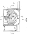
- FIG. 1 shows a current-limiting switching unit 10 which can be designed as an integral part of a low-voltage circuit breaker or which can form a unit which can be attached to an existing low-voltage circuit breaker in order to increase the breaking capacity of the circuit breaker.
- the current-limiting switching unit 10 contains a fixed contact arrangement 12, a movable contact bridge arrangement 14 with a contact bridge 15 and a carrier arrangement 16.
- a double arrow 17 denotes the direction of movement of the contact bridge 15 when opening and closing.
- An arc chamber 18 serves to extinguish the arc in the known manner.
- the carrier arrangement 16 exerts a closing force on the contact bridge arrangement 14, which brings the movable and stationary contacts into their closed position, in which the contacts touch one another.
- armature arrangements 36 and 38 reduce the biasing force acting in the sense of closing. the carrier arrangement 16 on the contact bridge arrangement and enable a quick and reliable opening due to a low fault current. With a high fault current, the magnetic repulsion is sufficient to separate the contacts. When the contacts are separated, the arcs are conducted into the arcing chamber 18 and extinguished there.
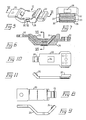
- the fixed contact arrangement 12 contains an input arm 20, an output arm 22, an input contact 24, which is attached to the end of the input arm 20, and an output contact 26, which is attached to the end of the output arm 22.
- the input arm and the output arm are encased in an encapsulation material 28 that electrically isolates the contact arms from each other.
- a first magnetic part 30 and a second magnetic part 32 are embedded in the encapsulation material, which are insulated from one another and from each of the contact arms by the encapsulation material 28.
- the first magnetic part 30 is preferably arranged between the input arm 20 and the output arm (22) and is located in the middle between them, so that it is located between the input contact 24 and the output contact 26, which project out of the encapsulation material 28 for proper contact with the contact bridge arrangement 14 are arranged. An edge or surface of the magnetic part 30 protrudes through the encapsulation material 28. If the second magnetic part 32 is also used, it is preferably arranged below the input arm 20. The second magnet part 32 receives its place on the bottom of the fixed contact arrangement 12.
- the output arm 22 has an opening 34 of a size which is sufficient to accommodate a part of the input arm 20.
- the output contact 26 is attached to one end of the contact arm 22, while the other end of the contact arm 22 has a configuration suitable for connection to the circuit breaker by means of a flexible conductor or other means.
- the end of the output arm 22 to which the output contact 26 is attached extends upwards at an angle. With this arrangement, the contact 26 protrudes from the encapsulation material 28 in the installed state.
- the input contact 24 is attached to one end of the input arm 20.
- the other end of the input arm is designed for connection to an input line.
- the input arm is formed from a flat piece of metal and has three bends. The first bend extends downward from the horizontal, the second bend returns the metal to the horizontal position, and the third bend extends the metal upward so that the contact 24 is approximately on the same horizontal plane as the connector portion of the contact arm 20.
- the three bends divide the contact arm 20 into two sections, namely a horizontal connecting section and a substantially U-shaped section, on one leg of which the input contact 24 is fastened.
- the section of the input arm 20 having this contact 24 is narrower than the rest of the input arm.
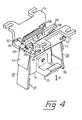
- the switching unit 10 has a first armature arrangement 36 and a second armature arrangement 38, which are connected at one end to the carrier arrangement 16, the other end extending downward in the vicinity of the fixed contact arrangement 12.
- Each of the armature arrangements 36 and 38 has a leaf spring 40 and 42, which is provided for biasing the armature arms in the direction of the fixed contact arrangement 12.
- the free end of each armature assembly extends near the magnetic parts 30 and 32 of the fixed contact assembly 12.
- a magnetic field exists in the vicinity of these magnetic parts during an overcurrent or a fault current. This magnetic field attracts the free end of each armature assembly towards the fixed contact assembly 12, which, as will be explained in detail, reduces the closing force and thereby enables the contacts to open more quickly under the influence of low fault currents.
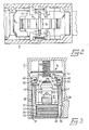
- the contact carrier assembly 16 has a contact carrier 44 which is gripped by carrier rollers 46 and 48, which are supported by carrier shafts 50 and 52, respectively.
- the ends of the carrier shafts are guided in elongated holes 55 of a support frame 54 such that they can be displaced transversely to the direction of movement of the contact bridge 15 and its contact carrier 44 (arrow 17).
- the support frame 54 is formed from a steel part in such a way that the central part of the metal has a U-shaped design, feet extending from the legs of the "U" for anchoring the support frame to the housing 11 of the switching unit 10 or a circuit breaker.
- the support frame 54 has an opening in the bottom of the U-shaped part of such a size and design that it is sufficient to receive the contact carrier 44.
- the support frame 54 also has slots 55 or other openings in the legs of the U-shaped part of such size and design that they are sufficient to receive the ends of the carrier shafts 50 and 52.
- the carrier rollers 46 and 48 are attached centrally to the carrier shafts 50 and 52. In a symmetrical arrangement on both sides of the carrier rollers 46 and 48, the carrier shafts 50 and 52 are prestressed against one another by coil tension springs 56 and 58.
- the contact carrier 44 is located between the carrier rollers 46 and 48 and is under the action of the coil tension springs 56 and 58.
- the carrier rollers 46 and 48 strive to pull each other.
- the contact carrier 44 has a first cam surface 60 and a second cam surface 62.
- the cam surfaces 60 and 62 are inclined differently inwards to the direction of movement (arrow 17) of the contact carrier 44 such that the carrier rollers 46 and 48 take the smallest distance from each other when the contacts are in the closed position shown in the figure.
- the carrier rollers 46 and 48 are removed from one another when the contacts come into the open position. In the illustrated closed position of the switching unit 10, the carrier rollers 46 and 48 bear against the cam surfaces 60 with the greater inclination and exert the required contact force on the contact carrier 44.
- the contact carrier 44 In the open position, the contact carrier 44 is displaced vertically upward in the drawing to such an extent that the carrier rollers 46 and 48 bear against the respectively assigned second cam surface 62. In this position of the parts, only a very slight force is exerted on the contact carrier in the direction of the closed position due to the lower inclination of the cam surfaces 62. The reduction in the action of force on the contact carrier 44 occurs abruptly when the carrier rollers 46 and 48 cross the transition region between the cam surfaces 60 and 62.
- the second cam surface 62 can be vertical, i. H. can be arranged without inclination to the direction of movement of the contact bridge 15.
- the contact carrier 44 can have a recess 64 for the engagement of a return spring 66, which is arranged between the contact carrier 44 and the housing 11 of the switching unit.
- This spring can be used optionally and is useful for providing a restoring force on the contact carrier 44 after the contacts have been opened due to a fault current.
- the spring can complement it by the carrier rollers and the second cam surfaces 62 generated force, or it can be used alone in cases where the cam surfaces 62 are made without inclination to the direction of movement.
- the spring 66 ensures that the pretensioning force in the closing direction is present regardless of influences such as dirt, foreign bodies or other causes.
- Each of the armature arrangements 36 and 38 extends with its free end into the area of the fixed contact arrangement 12 and is attracted by the magnetic parts 30 and 32 due to fault currents.
- Both anchor assemblies are formed by a flat steel part that is bent at two points to form a stepped shape at one end.
- the free end of each armature arrangement can be provided with an extension piece 37 or 39 in order to improve the response to the magnetic field formed by the magnetic parts 30 and 32.
- the anchor arrangements are angled twice in opposite directions, the first angle pointing towards the center line of the arrangement.
- the upward end portion 36a or 38a of each anchor assembly is bifurcated by a groove.
- a groove 36b can be seen in FIG.
- each anchor arrangement overlaps the associated support roller 46 and 48.
- the coil tension springs 56 and 58 are positioned next to the fork prongs of the end sections 36a and 38a.
- each bifurcated end section 36a and 38a engages behind the associated support shaft 50 and 52. This is created the possibility that each anchor arrangement due to its cutting-like mounting on the support frame 54 near the associated support roller can lift the latter from the contact carrier or reduce the force acting on the contact carrier 44. Since the armature arrangements 36 and 38, in conjunction with the magnet parts 30 and 32, already respond to low-level fault currents, rapid contact opening is ensured even with * low fault currents.
- left and right spacer blocks 68 and 70 are arranged in the housing 11 of the switching unit 10, which are made of a solid insulating material, e.g. are made of polyester resin with glass fiber reinforcement and act as guide parts for the contact carrier 44 during the opening and closing movement and for maintaining the separation between the magnetic parts 30 and 32 and the armature arrangements 36 and 38.
- the spacing blocks 68 and 70 are the same, but only the left block 68 will be described for ease of description.
- the spacer block 68 has essentially the cross-sectional shape of an I, similar to the cross-sectional shape of an I-steel.
- the head and foot legs of the I are the same, but the vertical middle part of the I is shifted to the right, so that the space remaining between the head and foot legs is larger on the left side than on the opposite side. Furthermore, the right side of the middle part has a groove 69.
- the spacer block 68 is arranged in the housing of the switching unit 10 between the armature arrangement 36 and the contact carrier 44, so that the contact carrier 44 can slide in the groove 69 of the spacer block 68. In this way, the groove 69 guides the contact carrier 44 during its upward and downward movement when opening and closing.
- the armature arrangement 36 extends through the space between the wall of the housing 11 of the switching unit 10 and the vertical middle part of the I-shape. This area can be viewed as a large groove which guides the armature arrangement laterally and which has the further important function of preventing the armature from contacting the magnet parts 30 and 32. These functions are important because the contact carrier 44 is produced as a relatively thin metal part that can be tilted when it comes into contact with the rollers, which would greatly change the opening and closing characteristics of the switch.
- the spacer block 68 or 70 thus represents a means for guiding the contact carrier 44, and thereby improves the response accuracy of the switching unit.
- the force exerted by the coil springs 56 and 58 tends to pull the carrier rollers 46 and 48 towards the center line of the carrier assembly 16. Since the armature assemblies 36 and 38 are engaged with the support shafts 50 and 52, a force acts on each armature assembly that would like to pull the bifurcated end 36a and 38a toward the center of the support assembly. This force is noticeable due to the cutting-like mounting of the armature arrangements below the forked end sections 36a and 38a in the sense of a removal of the lugs 37 and 39 from the magnetic parts 30 and 32. A leaf spring 40 or 41 attached to each of the armature arrangements 36 and 38 exerts a slight force in the sense of the pretensioning of the armature arrangements to the center line of the contact carrier.
- leaf springs compensate for differences in tolerance in the arrangement and ensure that the armature arrangements 36 and 38 are biased in the direction of the pole faces of the magnetic parts 30 and 32. It should be noted that the switching unit described can be manufactured economically because of manufacturing tolerances can be compensated for by the use of leaf springs 40 and 41. Even if the surface of the carrier rollers and the surfaces of the roller shafts and the forked end of the armature assemblies were made as precision parts, there could still be dimensional deviations. for example due to dirt or foreign bodies, which could cause a greater than the desired distance of the extensions 37 and 39 of the armature arrangements from the magnetic parts 30 and 32. The leaf springs ensure that the armature arrangements respond properly to low fault currents, while at the same time avoiding noise.
- the switching unit 10 is switched on, the fixed contact arrangement 12 and the bridge contact arrangement 14 being in contact with one another.
- a sufficient contact force exerted on the contacts minimizes the contact resistance and the contact heating due to the resistance when the current flows.
- the contact force is applied by coil springs 56 and 58 which exert a force on the carrier shafts 50 and 52 and the rollers 46 and 48 which in turn exert a force on the contact carrier 44 by acting on the cam surfaces 60. This force maintains the required contact force in order to ensure the lowest possible heating due to the contact resistance.
- the normal current flows through the input arm 20, the input contact 24 and the bridge contact arrangement 14 as well as through the output contact 26 and the output arm 22. This creates a unidirectional current flow in the encapsulated part of the fixed contact arrangement 12.
- the input arm and the output arm flow in the Current in the same direction. This results in twice the magnetic field for a current of a given size.
- the contact bridge arrangement 14 Through the contact bridge arrangement 14, the storm flows in the opposite direction as in the fixed contact arms 20 and 22. This generates an electromagnetic repulsive force. which, at sufficiently high currents, lifts the movable contact bridge arrangement 14 from the fixed contact arrangement 12.
- the current flowing through the switch increases, the current flowing through the fixed contact arrangement 12 excites the magnetic parts 30 and 32 to a sufficient extent to generate a magnetic field which attracts the armature arrangements 36 and 38.
- the magnetic parts and the air gap between the magnetic parts and the armature assemblies are calculated so that the armature moves toward the magnetic parts at a predetermined level of current.
- the forked end portions 36a and 38a are pivoted from the center line of the support assembly against the force of the coil springs 56 and 58. This reduces the downward biasing force on the carrier 44 and thus the force acting on the movable contact bridge arrangement 14. This also reduces the magnetic repulsive force that is required to separate the fixed and movable contacts.
- the current-limiting switching unit closes automatically after the interruption of a fault current due to the combined action of the tension springs 56 and 58 and the shape of the second cam surfaces 62, if the second cam surface 62 has an inclination that deviates from the vertical.
- the transition region between the first cam surface 60 and the second cam surface 62 at this point the downward force on the contact carrier 44 is suddenly greatly increased and the contacts are closed with the correct contact force.
- a return spring 66 can also be used to also provide a downward biasing force that biases the contacts to the closed position.
- Each of the two versions is applicable and sufficient; both can also be used in combination.
- the armature assemblies are attracted during a low level fault current and act to reduce the downward force. Due to a high fault current, however, the circuit is opened before the armature arrangements can take effect. However, the armatures are attracted by the short current flow that creates a magnetic field, although the circuit is open before the armature assemblies have the opportunity to move.
- the anchors respond to this and reduce the downward biasing force acting on the contact carrier 44 through the coil tension springs. This reduced force persists until the attractive force of the anchor arrangements is released. This force is a function of the size of the fault current. Thus, the higher the fault current, the longer the attractive force. This prevents the switch from closing before the fault current stops.
- the circuit breaker to be used in conjunction with the current limiting switch unit was rated for operation at 600 A.
- the breaking capacity of the current-limiting switching unit according to the invention was above 100,000 A at 480 V AC.
- the bridge contact arrangement for interrupting this extremely high current has a considerable weight, which hinders easy lifting of the bridge contact arrangement 14.
- the contacts would normally open at about 8000 A for a low level fault current, but the magnet arrangement causes the level to decrease to about 6000 A.
Landscapes
- Physics & Mathematics (AREA)
- Electromagnetism (AREA)
- Breakers (AREA)
- Arc-Extinguishing Devices That Are Switches (AREA)
Applications Claiming Priority (2)
| Application Number | Priority Date | Filing Date | Title |
|---|---|---|---|
| US718692 | 1985-04-01 | ||
| US06/718,692 US4633207A (en) | 1985-04-01 | 1985-04-01 | Cam following bridge contact carrier for a current limiting circuit breaker |
Publications (3)
| Publication Number | Publication Date |
|---|---|
| EP0199668A2 true EP0199668A2 (fr) | 1986-10-29 |
| EP0199668A3 EP0199668A3 (en) | 1988-06-01 |
| EP0199668B1 EP0199668B1 (fr) | 1992-03-04 |
Family
ID=24887110
Family Applications (1)
| Application Number | Title | Priority Date | Filing Date |
|---|---|---|---|
| EP86730061A Expired - Lifetime EP0199668B1 (fr) | 1985-04-01 | 1986-04-01 | Unité de commutation limitant le courant avec un dispositif d'un pont de contact |
Country Status (7)
| Country | Link |
|---|---|
| US (1) | US4633207A (fr) |
| EP (1) | EP0199668B1 (fr) |
| JP (1) | JPS61227340A (fr) |
| AU (1) | AU578000B2 (fr) |
| BR (1) | BR8601438A (fr) |
| DE (1) | DE3684032D1 (fr) |
| ZA (1) | ZA862312B (fr) |
Cited By (5)
| Publication number | Priority date | Publication date | Assignee | Title |
|---|---|---|---|---|
| RU2178217C1 (ru) * | 2000-08-23 | 2002-01-10 | Сергеев Дмитрий Анатольевич | Токоограничивающее устройство |
| RU2230387C2 (ru) * | 2002-08-26 | 2004-06-10 | Виктор Иванович Мрыхин | Токоограничивающее устройство |
| EP2565889A1 (fr) * | 2011-09-01 | 2013-03-06 | Socomec S.A. | Appareil de coupure électrique à haute tenue électrodynamique |
| US8859916B2 (en) | 2011-09-01 | 2014-10-14 | Socomec S.A. | Electrical cut-off device with high making capacity |
| US8993908B2 (en) | 2011-09-01 | 2015-03-31 | Socomec S.A. | Moving contact-carrying carriage and electrical cut-off device equipped with such carriage |
Families Citing this family (13)
| Publication number | Priority date | Publication date | Assignee | Title |
|---|---|---|---|---|
| US5072203A (en) * | 1989-09-18 | 1991-12-10 | Allen-Bradley Company, Inc. | Method and device for protecting starters from fault currents |
| US4991050A (en) * | 1989-09-18 | 1991-02-05 | Allen-Bradley Company, Inc. | Method and device for protecting starters from fault currents |
| US5892825A (en) * | 1996-05-15 | 1999-04-06 | Hyperlock Technologies Inc | Method of secure server control of local media via a trigger through a network for instant local access of encrypted data on local media |
| RU2230388C2 (ru) * | 2002-08-26 | 2004-06-10 | Виктор Иванович Мрыхин | Токоограничивающее устройство |
| US7023307B2 (en) * | 2003-11-06 | 2006-04-04 | Pratt & Whitney Canada Corp. | Electro-magnetically enhanced current interrupter |
| US11052784B2 (en) | 2017-11-08 | 2021-07-06 | Eaton Intelligent Power Limited | Power distribution unit and fuse management for an electric mobile application |
| US11070049B2 (en) | 2017-11-08 | 2021-07-20 | Eaton Intelligent Power Limited | System, method, and apparatus for power distribution in an electric mobile application using a combined breaker and relay |
| US11108225B2 (en) | 2017-11-08 | 2021-08-31 | Eaton Intelligent Power Limited | System, method, and apparatus for power distribution in an electric mobile application using a combined breaker and relay |
| US11368031B2 (en) | 2017-11-08 | 2022-06-21 | Eaton Intelligent Power Limited | Power distribution and circuit protection for a mobile application having a high efficiency inverter |
| CN108582038B (zh) * | 2018-04-10 | 2021-04-06 | 清华大学 | 一种模拟三轴数控机床加工的非接触式力加载装置 |
| US11689010B2 (en) | 2019-02-22 | 2023-06-27 | Eaton Intelligent Power Limited | Coolant fitting promoting turbulent flow |
| WO2021009217A2 (fr) | 2019-07-15 | 2021-01-21 | Eaton Intelligent Power Limited | Distribution de puissance et protection de circuit d'application mobile comportant un onduleur à haut rendement |
| RU2713439C1 (ru) * | 2019-07-24 | 2020-02-05 | Виктор Иванович Мрыхин | Способ ограничения тока короткого замыкания и устройство для его осуществления |
Family Cites Families (15)
| Publication number | Priority date | Publication date | Assignee | Title |
|---|---|---|---|---|
| US3575680A (en) * | 1969-08-08 | 1971-04-20 | Gen Electric | Current-limiting circuit breaker |
| US3575676A (en) * | 1969-11-04 | 1971-04-20 | Gen Electric | High-speed, high-current solenoid |
| US3588762A (en) * | 1970-02-25 | 1971-06-28 | Gen Electric | Circuit breaker with short circuit magnetic tripping means |
| US3588761A (en) * | 1970-02-26 | 1971-06-28 | Gen Electric | Electric circuit interrupter with magnetic trip level adjusting means |
| FR2185853B1 (fr) * | 1972-05-26 | 1977-12-30 | Merlin Gerin | |
| US3991391A (en) * | 1974-01-29 | 1976-11-09 | Westinghouse Electric Corporation | Circuit interrupter with electromagnetic opening means |
| US4118681A (en) * | 1976-05-12 | 1978-10-03 | Merlin Gerin | High-speed current-limiting device having a contact reclosing retarding member |
| DD127737A2 (de) * | 1976-09-30 | 1977-10-12 | Lothar Ackermann | Strombegrenzender selbstschalter |
| US4132968A (en) * | 1977-09-06 | 1979-01-02 | Westinghouse Electric Corp. | Current limiting circuit breaker with improved magnetic drive device |
| FR2458887A1 (fr) * | 1979-06-07 | 1981-01-02 | Hazemeyer Sa | Appareil de coupure de courant electrique du type limiteur d'intensite |
| US4409573A (en) * | 1981-04-23 | 1983-10-11 | Siemens-Allis, Inc. | Electromagnetically actuated anti-rebound latch |
| FR2511542A1 (fr) * | 1981-08-12 | 1983-02-18 | Telemecanique Electrique | Dispositif de liberation des contacts mobiles de contacteurs aptes a limiter les courants de courts-circuits |
| US4458224A (en) * | 1982-04-20 | 1984-07-03 | Siemens-Allis, Inc. | Current-limiting circuit breaker adapter |
| SE448794B (sv) * | 1983-07-04 | 1987-03-16 | Asea Ab | Strombegrensande elkopplare |
| US4630014A (en) * | 1985-04-01 | 1986-12-16 | Siemens Energy & Automation, Inc. | Current limiting circuit breaker stationary contact assembly with integral magnetic activating means |
-
1985
- 1985-04-01 US US06/718,692 patent/US4633207A/en not_active Expired - Lifetime
-
1986
- 1986-03-27 ZA ZA862312A patent/ZA862312B/xx unknown
- 1986-03-27 AU AU55327/86A patent/AU578000B2/en not_active Ceased
- 1986-03-28 JP JP61070665A patent/JPS61227340A/ja active Pending
- 1986-04-01 DE DE8686730061T patent/DE3684032D1/de not_active Expired - Lifetime
- 1986-04-01 BR BR8601438A patent/BR8601438A/pt unknown
- 1986-04-01 EP EP86730061A patent/EP0199668B1/fr not_active Expired - Lifetime
Cited By (7)
| Publication number | Priority date | Publication date | Assignee | Title |
|---|---|---|---|---|
| RU2178217C1 (ru) * | 2000-08-23 | 2002-01-10 | Сергеев Дмитрий Анатольевич | Токоограничивающее устройство |
| RU2230387C2 (ru) * | 2002-08-26 | 2004-06-10 | Виктор Иванович Мрыхин | Токоограничивающее устройство |
| EP2565889A1 (fr) * | 2011-09-01 | 2013-03-06 | Socomec S.A. | Appareil de coupure électrique à haute tenue électrodynamique |
| FR2979746A1 (fr) * | 2011-09-01 | 2013-03-08 | Socomec Sa | Appareil de coupure electrique a haute tenue electrodynamique |
| US8723627B2 (en) | 2011-09-01 | 2014-05-13 | Socomec, S.A. | Electrical cut-off device with high electrodynamic resistance |
| US8859916B2 (en) | 2011-09-01 | 2014-10-14 | Socomec S.A. | Electrical cut-off device with high making capacity |
| US8993908B2 (en) | 2011-09-01 | 2015-03-31 | Socomec S.A. | Moving contact-carrying carriage and electrical cut-off device equipped with such carriage |
Also Published As
| Publication number | Publication date |
|---|---|
| AU5532786A (en) | 1986-10-09 |
| US4633207A (en) | 1986-12-30 |
| EP0199668A3 (en) | 1988-06-01 |
| BR8601438A (pt) | 1986-12-09 |
| JPS61227340A (ja) | 1986-10-09 |
| DE3684032D1 (de) | 1992-04-09 |
| ZA862312B (en) | 1987-02-25 |
| EP0199668B1 (fr) | 1992-03-04 |
| AU578000B2 (en) | 1988-10-06 |
Similar Documents
| Publication | Publication Date | Title |
|---|---|---|
| DE3411275C2 (fr) | ||
| DE69302610T2 (de) | Kontakt für Lastschalter mit gegossenem Gehäuse | |
| EP0199668B1 (fr) | Unité de commutation limitant le courant avec un dispositif d'un pont de contact | |
| DE3034149C2 (de) | Lichtbogenlöscheinrichtung für Strombegrenzungs-Stromkreisunterbrecher | |
| DE4337344A1 (de) | Strombegrenzendes Kontaktsystem für Leistungsschalter | |
| DE69328444T3 (de) | Schalter | |
| DE3524827C2 (fr) | ||
| DE69028366T2 (de) | Schalter mit bewegbarem Magnetkern für magnetische Niederstromauslösung | |
| CH677045A5 (fr) | ||
| DE3750215T2 (de) | Schalter. | |
| DE3141958A1 (de) | "elektromagnetisch betaetigbarer elektrischer schalter" | |
| DE3280416T2 (de) | Leistungsschaltvorrichtung. | |
| DE69206749T2 (de) | Elektrischer Schützschalter mit Einfügung von zusätzlichen Windungen im Magnetauslöser | |
| EP0350825A2 (fr) | Appareil de commutation électrique | |
| DE2604314A1 (de) | Schaltkreisunterbrecher fuer kleine spannungen | |
| DE2258607A1 (de) | Ueberstromschalter | |
| EP1360709A1 (fr) | Dispositif a contact de commutation | |
| DE3303648C2 (fr) | ||
| DE10132858B4 (de) | Schutzschalter | |
| DE69030666T2 (de) | Ausschalter | |
| DE2138381C3 (de) | Schutzschalter, insbesondere Leitungsschutzschalter | |
| DE19854625A1 (de) | Kontaktanordnung für elektromagnetisches Schaltschütz | |
| DE112005003632B4 (de) | Leistungsschalter | |
| EP0196994A2 (fr) | Unité de commutation à limitation de courant avec une disposition localement parallèle des bras de contact | |
| EP0275517B1 (fr) | Disjoncteur de protection à maximum de courant, à rupture brusque pour appareils domestiques |
Legal Events
| Date | Code | Title | Description |
|---|---|---|---|
| PUAI | Public reference made under article 153(3) epc to a published international application that has entered the european phase |
Free format text: ORIGINAL CODE: 0009012 |
|
| AK | Designated contracting states |
Kind code of ref document: A2 Designated state(s): DE FR GB IT |
|
| PUAL | Search report despatched |
Free format text: ORIGINAL CODE: 0009013 |
|
| AK | Designated contracting states |
Kind code of ref document: A3 Designated state(s): DE FR GB IT |
|
| 17P | Request for examination filed |
Effective date: 19880627 |
|
| 17Q | First examination report despatched |
Effective date: 19901129 |
|
| GRAA | (expected) grant |
Free format text: ORIGINAL CODE: 0009210 |
|
| AK | Designated contracting states |
Kind code of ref document: B1 Designated state(s): DE FR GB IT |
|
| PG25 | Lapsed in a contracting state [announced via postgrant information from national office to epo] |
Ref country code: IT Free format text: LAPSE BECAUSE OF FAILURE TO SUBMIT A TRANSLATION OF THE DESCRIPTION OR TO PAY THE FEE WITHIN THE PRE;WARNING: LAPSES OF ITALIAN PATENTS WITH EFFECTIVE DATE BEFORE 2007 MAY HAVE OCCURRED AT ANY TIME BEFORE 2007. THE CORRECT EFFECTIVE DATE MAY BE DIFFERENT FROM THE ONE RECORDED.SCRIBED TIME-LIMIT Effective date: 19920304 Ref country code: FR Effective date: 19920304 Ref country code: GB Effective date: 19920304 |
|
| REF | Corresponds to: |
Ref document number: 3684032 Country of ref document: DE Date of ref document: 19920409 |
|
| EN | Fr: translation not filed | ||
| GBV | Gb: ep patent (uk) treated as always having been void in accordance with gb section 77(7)/1977 [no translation filed] | ||
| PLBE | No opposition filed within time limit |
Free format text: ORIGINAL CODE: 0009261 |
|
| STAA | Information on the status of an ep patent application or granted ep patent |
Free format text: STATUS: NO OPPOSITION FILED WITHIN TIME LIMIT |
|
| 26N | No opposition filed | ||
| PGFP | Annual fee paid to national office [announced via postgrant information from national office to epo] |
Ref country code: DE Payment date: 19930618 Year of fee payment: 8 |
|
| PG25 | Lapsed in a contracting state [announced via postgrant information from national office to epo] |
Ref country code: DE Effective date: 19950103 |