EP0199674A1 - Corps de remplissage en matière synthétique résistant aux acides - Google Patents
Corps de remplissage en matière synthétique résistant aux acides Download PDFInfo
- Publication number
- EP0199674A1 EP0199674A1 EP86810169A EP86810169A EP0199674A1 EP 0199674 A1 EP0199674 A1 EP 0199674A1 EP 86810169 A EP86810169 A EP 86810169A EP 86810169 A EP86810169 A EP 86810169A EP 0199674 A1 EP0199674 A1 EP 0199674A1
- Authority
- EP
- European Patent Office
- Prior art keywords
- wall
- packing
- body according
- packing body
- walls
- Prior art date
- Legal status (The legal status is an assumption and is not a legal conclusion. Google has not performed a legal analysis and makes no representation as to the accuracy of the status listed.)
- Withdrawn
Links
- 239000000463 material Substances 0.000 title claims description 6
- 229920002994 synthetic fiber Polymers 0.000 title 1
- 239000000945 filler Substances 0.000 claims abstract description 22
- 230000007423 decrease Effects 0.000 claims abstract 2
- 238000012856 packing Methods 0.000 claims description 62
- 238000005192 partition Methods 0.000 claims description 20
- 239000004033 plastic Substances 0.000 claims description 6
- 229920003023 plastic Polymers 0.000 claims description 6
- 239000002253 acid Substances 0.000 claims description 4
- 238000010276 construction Methods 0.000 claims description 2
- 210000004027 cell Anatomy 0.000 abstract description 13
- 239000013256 coordination polymer Substances 0.000 abstract description 8
- 210000002421 cell wall Anatomy 0.000 abstract description 4
- 238000004519 manufacturing process Methods 0.000 abstract description 4
- 239000007789 gas Substances 0.000 description 4
- 238000000034 method Methods 0.000 description 3
- AAJFWZPKEVPIMB-UHFFFAOYSA-N [N]=O.OS(O)(=O)=O Chemical compound [N]=O.OS(O)(=O)=O AAJFWZPKEVPIMB-UHFFFAOYSA-N 0.000 description 2
- 239000007788 liquid Substances 0.000 description 2
- 239000002184 metal Substances 0.000 description 2
- 229910052751 metal Inorganic materials 0.000 description 2
- 229920002981 polyvinylidene fluoride Polymers 0.000 description 2
- 206010052904 Musculoskeletal stiffness Diseases 0.000 description 1
- 239000002033 PVDF binder Substances 0.000 description 1
- 239000004698 Polyethylene Substances 0.000 description 1
- 238000006887 Ullmann reaction Methods 0.000 description 1
- 239000000919 ceramic Substances 0.000 description 1
- 238000001311 chemical methods and process Methods 0.000 description 1
- 238000004140 cleaning Methods 0.000 description 1
- 229930195733 hydrocarbon Natural products 0.000 description 1
- 150000002430 hydrocarbons Chemical class 0.000 description 1
- 150000002739 metals Chemical class 0.000 description 1
- -1 polyethylene Polymers 0.000 description 1
- 229920000573 polyethylene Polymers 0.000 description 1
- 229920000642 polymer Polymers 0.000 description 1
- 239000000126 substance Substances 0.000 description 1
Images

Classifications
-
- F—MECHANICAL ENGINEERING; LIGHTING; HEATING; WEAPONS; BLASTING
- F28—HEAT EXCHANGE IN GENERAL
- F28F—DETAILS OF HEAT-EXCHANGE AND HEAT-TRANSFER APPARATUS, OF GENERAL APPLICATION
- F28F25/00—Component parts of trickle coolers
- F28F25/02—Component parts of trickle coolers for distributing, circulating, and accumulating liquid
- F28F25/08—Splashing boards or grids, e.g. for converting liquid sprays into liquid films; Elements or beds for increasing the area of the contact surface
- F28F25/085—Substantially horizontal grids; Blocks
-
- B—PERFORMING OPERATIONS; TRANSPORTING
- B01—PHYSICAL OR CHEMICAL PROCESSES OR APPARATUS IN GENERAL
- B01J—CHEMICAL OR PHYSICAL PROCESSES, e.g. CATALYSIS OR COLLOID CHEMISTRY; THEIR RELEVANT APPARATUS
- B01J19/00—Chemical, physical or physico-chemical processes in general; Their relevant apparatus
- B01J19/30—Loose or shaped packing elements, e.g. Raschig rings or Berl saddles, for pouring into the apparatus for mass or heat transfer
-
- B—PERFORMING OPERATIONS; TRANSPORTING
- B01—PHYSICAL OR CHEMICAL PROCESSES OR APPARATUS IN GENERAL
- B01J—CHEMICAL OR PHYSICAL PROCESSES, e.g. CATALYSIS OR COLLOID CHEMISTRY; THEIR RELEVANT APPARATUS
- B01J2219/00—Chemical, physical or physico-chemical processes in general; Their relevant apparatus
- B01J2219/30—Details relating to random packing elements
- B01J2219/302—Basic shape of the elements
- B01J2219/30215—Toroid or ring
-
- B—PERFORMING OPERATIONS; TRANSPORTING
- B01—PHYSICAL OR CHEMICAL PROCESSES OR APPARATUS IN GENERAL
- B01J—CHEMICAL OR PHYSICAL PROCESSES, e.g. CATALYSIS OR COLLOID CHEMISTRY; THEIR RELEVANT APPARATUS
- B01J2219/00—Chemical, physical or physico-chemical processes in general; Their relevant apparatus
- B01J2219/30—Details relating to random packing elements
- B01J2219/302—Basic shape of the elements
- B01J2219/3023—Triangle
-
- B—PERFORMING OPERATIONS; TRANSPORTING
- B01—PHYSICAL OR CHEMICAL PROCESSES OR APPARATUS IN GENERAL
- B01J—CHEMICAL OR PHYSICAL PROCESSES, e.g. CATALYSIS OR COLLOID CHEMISTRY; THEIR RELEVANT APPARATUS
- B01J2219/00—Chemical, physical or physico-chemical processes in general; Their relevant apparatus
- B01J2219/30—Details relating to random packing elements
- B01J2219/304—Composition or microstructure of the elements
- B01J2219/30466—Plastics
-
- Y—GENERAL TAGGING OF NEW TECHNOLOGICAL DEVELOPMENTS; GENERAL TAGGING OF CROSS-SECTIONAL TECHNOLOGIES SPANNING OVER SEVERAL SECTIONS OF THE IPC; TECHNICAL SUBJECTS COVERED BY FORMER USPC CROSS-REFERENCE ART COLLECTIONS [XRACs] AND DIGESTS
- Y10—TECHNICAL SUBJECTS COVERED BY FORMER USPC
- Y10S—TECHNICAL SUBJECTS COVERED BY FORMER USPC CROSS-REFERENCE ART COLLECTIONS [XRACs] AND DIGESTS
- Y10S261/00—Gas and liquid contact apparatus
- Y10S261/72—Packing elements
-
- Y—GENERAL TAGGING OF NEW TECHNOLOGICAL DEVELOPMENTS; GENERAL TAGGING OF CROSS-SECTIONAL TECHNOLOGIES SPANNING OVER SEVERAL SECTIONS OF THE IPC; TECHNICAL SUBJECTS COVERED BY FORMER USPC CROSS-REFERENCE ART COLLECTIONS [XRACs] AND DIGESTS
- Y10—TECHNICAL SUBJECTS COVERED BY FORMER USPC
- Y10T—TECHNICAL SUBJECTS COVERED BY FORMER US CLASSIFICATION
- Y10T428/00—Stock material or miscellaneous articles
- Y10T428/24—Structurally defined web or sheet [e.g., overall dimension, etc.]
- Y10T428/24149—Honeycomb-like
Definitions
- the invention relates to a packing according to the preamble of claim 1.
- the outer wall of the packing according to the invention can be closed along a main plane of the packing with a round, preferably circular or elliptical, or also with at least approximately polygonal, e.g. three, four, five, six or polygonal design of your floor plan.
- the thickness of all cell walls or a part of the cell walls is chosen to be less than 0.8 mm or even 0.5 mm and in special cases even less than 0.3 mm.
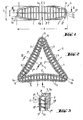
- the embodiment of the filler body according to the invention shown in Figures 1 to 3 comprises a circumferential outer wall 1 which has a cross-sectional outline of a basically triangular shape and has three corner regions la, lb and lc.
- the lateral wall sections 1 ', 1 "and 1"' of the outer wall 1 between these corner areas are slightly concavely curved towards the center of the body.
- the inside of the triangle comprises an inner wall 2, which consists of three wall parts 2 ', 2 "and 2'", the ends of which protrude somewhat from the corner regions la, lb and lc in end pieces 2a, 2b and 2c.
- Each of the inner wall sections 2 ', 2 "and 2"' has a concave shape, its curvature being somewhat greater than that of the sections of the outer wall 1.
- the height of the walls 1 and 2 is greatest in the middle of each wall section between the corner regions la, lb and lc and lowest in these corner regions, as can be seen from FIG. 1.
- the outer wall sections 1 ', 1 "and 1"' are connected to the adjacent inner wall sections 2 ', 2 "and 2"' by transverse dividing walls 3, which each of the gaps between the wall sections 1 'and 2', between 1 "and 2 ", or divide between 1" 'and 2 "' into cells 5, which are open at the head end 5a and at the bottom end 5b of the packing 6.
- the resulting packing 6 can e.g. be made of the above-mentioned plastic in two halves 6 'and 6 ", which can be glued or welded together, so that the partition halves 3' of the upper filler half 6 'are aligned with the corresponding partition halves 3" in the lower filler half 6 "and so each the entire partition 3 is created.
- the upper filler half 6 'and the lower filler half 6 can be glued or welded to one another along a common parting line running in a common central plane CP, wherever the halves of the walls 1, 2 and 3 are placed one above the other and touch or cross.
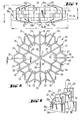
- the endless outer wall 11 of the filling body extends in an approximately triangular shape between convexly curved corner regions 11a, 11b and 11c, and the inner wall 12 is from the inside, i.e. curved (concave) wall sections 12 ', 12 "and 12"' towards the center of the packing, which are formed together in their end pieces 12a, 12b and 12c. are welded, / These end pieces protrude slightly beyond the outer wall 11 in the corner areas.
- the filler body 10 is preferably composed of an upper half lOx and a lower half lOy, which are glued or welded to one another at the parting line CP ' in which the outer and inner half walls 11x and 12x of the walls 11 and 12 are seated on the lower outer and inner half walls lly and 12y, respectively.
- the space between each section of the outer and inner walls, for example between 11 'and 12', or between 11 "and 12", or finally between 11 "'and 12"' in one Number of cells 15 are subdivided by transverse dividing walls 13, which terminate downwards with the lower edges of the upper halves 11x and 12x of the outer wall 11 and the inner wall 12 at the parting line CP '. At the top, they protrude considerably beyond the upper edges llu and 12u of the upper wall halves llx and 12x, respectively (see FIG. 6).
- the partitions 13 'and 13 "closest to and beyond the end regions 11a, 11b and 11c are angle pieces which extend over the two spaces adjoining the corner region, while the between the corner areas after the middle of the triangular partition walls 13 are only long enough to bridge one of the intermediate spaces and not also the one adjacent to it in the upper half of the packing.
- the space between adjacent sections of the outer and inner wall in the named areas 11 ', 12' or 11 ", 12", or also 11 "', 12"' is divided into a number of cells by transverse dividing walls 14 divided upwards at the level of the parting line CP 'between the upper and lower filler half lOx, or lOy with the upper edges of the lower wall halves lly or 12y of the outer or inner wall, 11 or 12, in alignment end up.
- the transverse walls 14 extend downward a good way beyond the lower edges 11w and 12w of the lower wall halves 11y and 12y (see FIG. 6).
- transverse walls 13 and 14 in the upper and lower half of the packing lOx and lOy, respectively, do not align with one another, as is the case with the partition halves 3 'and 3 "in the embodiment described above. Rather, the partition walls 13 are in relation to FIG the partitions 14 moved, so that there is a staggered arrangement of the cells or the transverse walls 13 and 14.
- the closest to each of the corner areas 11a, 11b and 11c and also the next but one partition 14 are angle pieces which cross in one piece the two intermediate spaces projecting into the relevant corner area.
- the dividing walls 14 crossing the centers of the sections 11 ', 11 "and 11"' of the outer wall and the corresponding sections of the inner wall 12 can also be firmly connected to one another in the center of the filling body and thus form an integral three-flange dividing wall 14z.
- stiffening walls or webs can also be provided in the interior of the filling body 10 or of the filling body 20 described below be, which extend axially or radially with respect to the central axis running through the center C of the filler body to the plane in which the cross-sectional views of FIGS. 2 and 5 lie. Such stiffening walls or webs also advantageously increase the total surface area of the packing, but must not complicate their manufacture.
- a circular or another round e.g. an elliptical arrangement can be selected, or it can be square, pentagonal, etc.
- a hexagonal arrangement is selected.
- the filling body 20 according to the invention is based on a cross section of a hexagonal arrangement, the filling body having an outer side wall 21, an inner wall 22 and in the upper and lower half of the filling body, 20x and 20y, transverse to these walls has partition walls 23 and 24 which divide the annular space between the outer wall 21 and the inner wall 22 into cells 25 which are open at the upper packing end 25a and at the lower end 25b thereof.
- the height of the self-contained outer wall 21 is lower than that of the inner wall 22 (FIG. 9).
- partitions 27, 28 and 29 are provided, which extend as continuous radial transverse walls through the center of the packing C and are rigidly connected to one another in it, so that they form a one-piece separating element with six flanges.
- the packing is advantageously designed as a relatively flat structure, the height h of the packing being smaller than its width d.
Landscapes
- Physics & Mathematics (AREA)
- Thermal Sciences (AREA)
- Engineering & Computer Science (AREA)
- Chemical & Material Sciences (AREA)
- Mechanical Engineering (AREA)
- General Engineering & Computer Science (AREA)
- Organic Chemistry (AREA)
- Chemical Kinetics & Catalysis (AREA)
- Physical Or Chemical Processes And Apparatus (AREA)
- Sealing Material Composition (AREA)
Applications Claiming Priority (2)
| Application Number | Priority Date | Filing Date | Title |
|---|---|---|---|
| CH1608/85 | 1985-04-16 | ||
| CH160885 | 1985-04-16 |
Publications (1)
| Publication Number | Publication Date |
|---|---|
| EP0199674A1 true EP0199674A1 (fr) | 1986-10-29 |
Family
ID=4214409
Family Applications (1)
| Application Number | Title | Priority Date | Filing Date |
|---|---|---|---|
| EP86810169A Withdrawn EP0199674A1 (fr) | 1985-04-16 | 1986-04-10 | Corps de remplissage en matière synthétique résistant aux acides |
Country Status (2)
| Country | Link |
|---|---|
| US (1) | US4716066A (fr) |
| EP (1) | EP0199674A1 (fr) |
Cited By (2)
| Publication number | Priority date | Publication date | Assignee | Title |
|---|---|---|---|---|
| WO1998004343A1 (fr) * | 1996-07-29 | 1998-02-05 | Norton Chemical Process Products Corporation | Element de remplissage de colonne |
| FR2813040A1 (fr) | 2000-06-30 | 2002-02-22 | Avery Dennison Corp | Reliure pouvant etre dessinee et/ou tracee |
Families Citing this family (10)
| Publication number | Priority date | Publication date | Assignee | Title |
|---|---|---|---|---|
| US6699562B2 (en) * | 2002-02-28 | 2004-03-02 | Saint-Gobain Corporation | Ceramic packing element |
| KR20050084671A (ko) * | 2002-11-05 | 2005-08-26 | 엔.브이. 베카에르트 에스.에이. | 적외선 반사층 구조 |
| EP2101134A1 (fr) * | 2008-02-28 | 2009-09-16 | Paul Wurth Refractory & Engineering GmbH | Brique trouée |
| CN103733117B (zh) | 2010-10-18 | 2016-09-28 | 瑞琪3D医疗有限责任公司 | 立体光学系统 |
| WO2012068137A1 (fr) | 2010-11-15 | 2012-05-24 | Medivision, Inc. | Optique relais stéréoscopique |
| US20150211804A1 (en) * | 2014-01-28 | 2015-07-30 | Kunshan Jue-Chung Electronics Co., Ltd. | Energy storage assembly and energy storage element thereof |
| US10744426B2 (en) * | 2015-12-31 | 2020-08-18 | Crystaphase Products, Inc. | Structured elements and methods of use |
| US10054140B2 (en) | 2016-02-12 | 2018-08-21 | Crystaphase Products, Inc. | Use of treating elements to facilitate flow in vessels |
| EP4076719A1 (fr) | 2019-12-20 | 2022-10-26 | Crystaphase Products Inc. | Resaturation de gaz dans un courant d'alimentation en liquide |
| JP2023541252A (ja) | 2020-09-09 | 2023-09-29 | クリスタフェーズ・プロダクツ・インコーポレーテッド | プロセス容器進入ゾーン |
Citations (2)
| Publication number | Priority date | Publication date | Assignee | Title |
|---|---|---|---|---|
| DE2738362A1 (de) * | 1976-04-15 | 1979-03-01 | Acalor Int Ltd | Beliebige packmaterialien |
| GB2093728A (en) * | 1981-02-20 | 1982-09-08 | Aaltosen Tehtaat Oy | Packing element for a biological filter or for use in mass transfer |
Family Cites Families (9)
| Publication number | Priority date | Publication date | Assignee | Title |
|---|---|---|---|---|
| US3506248A (en) * | 1968-02-21 | 1970-04-14 | United Air Specialists | Tower packing unit |
| US3957931A (en) * | 1970-12-18 | 1976-05-18 | Mass Transfer Limited | Fluid-fluid contact method and apparatus |
| US4072736A (en) * | 1974-04-05 | 1978-02-07 | Ciba-Geigy Corporation | Packing material |
| US4148868A (en) * | 1975-03-10 | 1979-04-10 | Ciba-Geigy Corporation | Process for separating SO2 from a current of gas containing the same |
| ZA762830B (en) * | 1975-05-21 | 1977-04-27 | Norton Co | Trickling filters media for biological filters |
| DE2830214A1 (de) * | 1977-07-21 | 1979-02-08 | Ciba Geigy Ag | Verfahren zum abtrennen von so tief 2 aus einem gasstrom und anlage zur durchfuehrung des verfahrens |
| US4195043A (en) * | 1979-01-17 | 1980-03-25 | Norton Company | Randomly dumpable self orienting spiral packing elements |
| DE3221128A1 (de) * | 1982-06-04 | 1983-12-08 | Paul Rauschert Gmbh & Co Kg, 8644 Pressig | Ringfoermiger fuellkoerper fuer gas-fluessigkeitskontakt |
| US4511519A (en) * | 1984-04-30 | 1985-04-16 | Norton Company | Tower packing elements |
-
1986
- 1986-04-04 US US06/848,052 patent/US4716066A/en not_active Expired - Fee Related
- 1986-04-10 EP EP86810169A patent/EP0199674A1/fr not_active Withdrawn
Patent Citations (2)
| Publication number | Priority date | Publication date | Assignee | Title |
|---|---|---|---|---|
| DE2738362A1 (de) * | 1976-04-15 | 1979-03-01 | Acalor Int Ltd | Beliebige packmaterialien |
| GB2093728A (en) * | 1981-02-20 | 1982-09-08 | Aaltosen Tehtaat Oy | Packing element for a biological filter or for use in mass transfer |
Cited By (3)
| Publication number | Priority date | Publication date | Assignee | Title |
|---|---|---|---|---|
| WO1998004343A1 (fr) * | 1996-07-29 | 1998-02-05 | Norton Chemical Process Products Corporation | Element de remplissage de colonne |
| RU2160629C2 (ru) * | 1996-07-29 | 2000-12-20 | Нортон Кемикал Проусесс Продактс Корпорейшн | Насадочный элемент колонны |
| FR2813040A1 (fr) | 2000-06-30 | 2002-02-22 | Avery Dennison Corp | Reliure pouvant etre dessinee et/ou tracee |
Also Published As
| Publication number | Publication date |
|---|---|
| US4716066A (en) | 1987-12-29 |
Similar Documents
| Publication | Publication Date | Title |
|---|---|---|
| DE3114617C2 (fr) | ||
| EP0784507B1 (fr) | Microstructures croisees | |
| DE10392798B4 (de) | Keramisches Füllkörperelement | |
| EP0199674A1 (fr) | Corps de remplissage en matière synthétique résistant aux acides | |
| EP0096267B2 (fr) | Elément de garnissage annulaire pour contact gaz-liquide | |
| EP0418338A1 (fr) | Garniture a passages multiples pour la generation de tourbillons. | |
| DE69936299T2 (de) | Schwimmende seestruktur mit destillationsäule | |
| DE2738362C2 (de) | Füllkörper | |
| EP0775606B1 (fr) | Réservoir, notamment pour véhicules automobiles | |
| DE69314410T2 (de) | Gitterpackungselement für Gas-Flüssig-Kontaktapparate | |
| DE3515300A1 (de) | Pyramidenpackung fuer die verfahrenstechnik | |
| DE2845804A1 (de) | Fuellkoerper fuer vorrichtungen zum inberuehrungbringen von gasen und fluessigkeiten | |
| DE69701744T2 (de) | Füllkörper für kolonne | |
| DE2746079C3 (de) | Trockendock-Hubplattform | |
| DE2313287A1 (de) | Fuellkoerper | |
| DE3111930A1 (de) | Gestaenge-verbindungsklemme | |
| DE7719231U1 (de) | Metallgitterrost | |
| DE3150216A1 (de) | Fuellkoerper | |
| EP0197162B1 (fr) | Caisses à bouteilles | |
| EP3254754B1 (fr) | Corps de remplissage | |
| DE2823726A1 (de) | Fuellkoerper | |
| DE69204750T2 (de) | Stapelfähiger Flaschenkasten. | |
| DE60103558T2 (de) | Bauelement und damit errichtete stützwand | |
| DE3106561C2 (fr) | ||
| DE3129229A1 (de) | "flaschenkasten aus kunststoff" |
Legal Events
| Date | Code | Title | Description |
|---|---|---|---|
| PUAI | Public reference made under article 153(3) epc to a published international application that has entered the european phase |
Free format text: ORIGINAL CODE: 0009012 |
|
| 17P | Request for examination filed |
Effective date: 19860412 |
|
| AK | Designated contracting states |
Kind code of ref document: A1 Designated state(s): AT BE CH DE FR GB LI NL |
|
| 17Q | First examination report despatched |
Effective date: 19871012 |
|
| STAA | Information on the status of an ep patent application or granted ep patent |
Free format text: STATUS: THE APPLICATION IS DEEMED TO BE WITHDRAWN |
|
| 18D | Application deemed to be withdrawn |
Effective date: 19880222 |
|
| RIN1 | Information on inventor provided before grant (corrected) |
Inventor name: FATTINGER, VOLKER, DR. Inventor name: WYMANN, PAUL |