EP0199695A2 - Stabilisateur optimal de réseau utilisant des variables de simulation d'état - Google Patents
Stabilisateur optimal de réseau utilisant des variables de simulation d'état Download PDFInfo
- Publication number
- EP0199695A2 EP0199695A2 EP86850138A EP86850138A EP0199695A2 EP 0199695 A2 EP0199695 A2 EP 0199695A2 EP 86850138 A EP86850138 A EP 86850138A EP 86850138 A EP86850138 A EP 86850138A EP 0199695 A2 EP0199695 A2 EP 0199695A2
- Authority
- EP
- European Patent Office
- Prior art keywords
- deviation
- circuit
- power system
- power
- angular frequency
- Prior art date
- Legal status (The legal status is an assumption and is not a legal conclusion. Google has not performed a legal analysis and makes no representation as to the accuracy of the status listed.)
- Withdrawn
Links
Images

Classifications
-
- H—ELECTRICITY
- H02—GENERATION; CONVERSION OR DISTRIBUTION OF ELECTRIC POWER
- H02P—CONTROL OR REGULATION OF ELECTRIC MOTORS, ELECTRIC GENERATORS OR DYNAMO-ELECTRIC CONVERTERS; CONTROLLING TRANSFORMERS, REACTORS OR CHOKE COILS
- H02P9/00—Arrangements for controlling electric generators for the purpose of obtaining a desired output
- H02P9/10—Control effected upon generator excitation circuit to reduce harmful effects of overloads or transients, e.g. sudden application of load, sudden removal of load, sudden change of load
- H02P9/105—Control effected upon generator excitation circuit to reduce harmful effects of overloads or transients, e.g. sudden application of load, sudden removal of load, sudden change of load for increasing the stability
Definitions
- the present invention relates to an automatic device which can be used to depress the low frequency oscillation of a power system.
- PSS power system stabilizers
- optimal control excitation were used to depress the low frequency oscillation. If merely the measuring of voltage deviation is taken, the control effects of both measures would not be satisfactory and it is hard to depress the low frequency oscillation. Therefore, other variables that could reflect the state of steady must be measured and used as additional feedback regulating variables. Generally speaking, the effect of PSS was not satisfactory while the optimal control was too complicated to realize, and both had the defects of difficult realization, distortions, low reliability, complicate and heavy measuring devices, etc.
- the present invention proposes a kind of simple, reliable electronic circuit which can realize the optimal control almost as theroretical demand, depress the low frequency oscillation, and raise the output of generator even to its limit while maintaining its stability.
- the present invention is characterized in that the full state optimal control is realized to depress the low frequency oscillation by using a certain state variable, e.g. the voltage deviation instead of using the complicate direct measurement of additional feedback.
- All of the state variables needed to realize optimal control comes from an analogous electronic circuit with voltage deviation ⁇ V being its input and the simulating state variables needed being its outputs. Incorporating the analogous electronic circuit of the present invention in the amplifier block of the original excitation control system will depress low frequency oscillation of power systems.
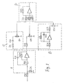
- the electronic circuit of Type I comprises a bandpass filter circuit A with its transfer function being an integral circuit B with its transfer function being a differential circuit C with its transfer function being and an additor circuit D.
- the filter circuit A is used to transfer the voltage deviation ⁇ V into the angular frequency deviation ⁇ ⁇ while the integral circuit B and the differential circuit C are used to transfer the angular frequency deviation ⁇ respectively into the power angle deviation ⁇ and the power deviation ⁇ p,
- the electronic circuit of Type II comprises a bandpass filter circuit A with its transfer function being which has an integral circuit B with its transfer function being , a seperate differential circuit C with its transfer function being , and a seperate additor circuit D.
- the filter circuit A is used to transfer the voltage deviation ⁇ V into the angular frequency deviation ⁇ , and meanwhile through its integral circuit B to get the deviation ⁇ .
- the differential circuit C is used to transfer ⁇ into the _power deviation A p. After their coefficients are respectively regulated by corresponding potentialmenters, the three deviations, ⁇ , ⁇ , and ⁇ are added by the additor circuit D.
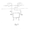
- Both Type I and II analogous circuits of simulating state variable stabilizers shown in line in Fig. 3 can be connected to every amplifier block of the original excitation system shown in dotted line in Fig. 3, thus being able to depress the low frequency oscillation of power systems. In this way, the adjustment of the original circuit can be maintained unchanged and the effect of the gain of ⁇ V can be considered in the coefficients of ⁇ , AS and ⁇ .
- the present device was put into a trial operation in a hydropower plant of a capacity of 965 MW.
- the present device Under the use of two 141.4 MVA generators having fast excitation control thyristor systems, two transformers of 150 MVA, and a transmission line of 220KV, the present device underwent an on-the-spot test by connecting the two generator- transformer sets to the system by the same bus through one transmission line. The test result was completely the same with that obtained in the dynamic analogous laboratory.
- the two generators generated 225MW, of which 190MW was sent to the system while 35MW was local load, the local load was cut off suddenly and the waves of power in the transmission line is recorded.
- the alternative components of power that periodical changes every second will diverge at a time constant of 14 seconds, yet, with the use of the present device, the alternative components will converge at a time constant of 2.8 seconds.
Landscapes
- Engineering & Computer Science (AREA)
- Power Engineering (AREA)
- Control Of Eletrric Generators (AREA)
- Supply And Distribution Of Alternating Current (AREA)
Applications Claiming Priority (2)
| Application Number | Priority Date | Filing Date | Title |
|---|---|---|---|
| CN85103037 | 1985-04-18 | ||
| CN85103037A CN85103037B (zh) | 1985-04-18 | 1985-04-18 | 仿真状态量最优控制电力系统稳定器 |
Publications (2)
| Publication Number | Publication Date |
|---|---|
| EP0199695A2 true EP0199695A2 (fr) | 1986-10-29 |
| EP0199695A3 EP0199695A3 (fr) | 1988-03-16 |
Family
ID=4792937
Family Applications (1)
| Application Number | Title | Priority Date | Filing Date |
|---|---|---|---|
| EP86850138A Withdrawn EP0199695A3 (fr) | 1985-04-18 | 1986-04-17 | Stabilisateur optimal de réseau utilisant des variables de simulation d'état |
Country Status (4)
| Country | Link |
|---|---|
| US (1) | US4701689A (fr) |
| EP (1) | EP0199695A3 (fr) |
| JP (1) | JPS61280715A (fr) |
| CN (1) | CN85103037B (fr) |
Cited By (2)
| Publication number | Priority date | Publication date | Assignee | Title |
|---|---|---|---|---|
| EP0456521A1 (fr) * | 1990-05-11 | 1991-11-13 | Kabushiki Kaisha Toshiba | Appareil de contrôle d'un système de puissance |
| EP0713287A1 (fr) * | 1994-11-15 | 1996-05-22 | Kabushiki Kaisha Toshiba | Stabilisateur de système d'alimentation pour générateur |
Families Citing this family (17)
| Publication number | Priority date | Publication date | Assignee | Title |
|---|---|---|---|---|
| JPH07108063B2 (ja) * | 1986-01-06 | 1995-11-15 | 中部電力株式会社 | 系統安定化装置 |
| EP0268160A1 (fr) * | 1986-11-17 | 1988-05-25 | GebràDer Sulzer Aktiengesellschaft | Méthode et appareil à réduire au moins un facteur de fréquence d'une pulsation périodique |
| US4855664A (en) * | 1988-06-10 | 1989-08-08 | General Electric Company | Method and apparatus for damping oscillations of an ac generator |
| US4999564A (en) * | 1989-10-12 | 1991-03-12 | General Electric Company | Power system stabilizer system having improved integrity checking scheme |
| US5216621A (en) * | 1991-02-28 | 1993-06-01 | Mehta Tech. Inc. | Line disturbance monitor and recorder system |
| US5227713A (en) * | 1991-08-08 | 1993-07-13 | Electric Power Research Institute | Vernier control system for subsynchronous resonance mitigation |
| US5483147A (en) * | 1992-07-10 | 1996-01-09 | Massachusetts Institute Of Technology | Decentralized excitation control for an electrical power utility system |
| US5440935A (en) * | 1993-03-18 | 1995-08-15 | Mts Systems Corporation | Apparatus for combining transducer output signals |
| US5703791A (en) * | 1994-02-17 | 1997-12-30 | Hitachi, Ltd. | Electric power system stabilization control apparatus and method thereof |
| JP4034397B2 (ja) * | 1998-01-13 | 2008-01-16 | 中部電力株式会社 | 系統安定化装置 |
| JP3558919B2 (ja) * | 1999-04-14 | 2004-08-25 | 三菱電機株式会社 | 励磁制御装置及び励磁制御方法 |
| JP4073776B2 (ja) * | 2002-12-19 | 2008-04-09 | 三菱電機株式会社 | 励磁制御装置 |
| US8340931B2 (en) * | 2009-10-05 | 2012-12-25 | Mehta Tech, Inc. | Power grid with comparison of differences in remote phasor changes |
| CN103051265A (zh) * | 2012-12-26 | 2013-04-17 | 浙江大学 | 一种电力系统故障情况下的发电机强励控制方法 |
| CN104951900B (zh) * | 2015-06-30 | 2018-08-31 | 贵州电力试验研究院 | 一种电力系统稳定器的性能评估装置 |
| CN110266047B (zh) * | 2019-07-04 | 2021-01-15 | 华中科技大学 | 一种基于自适应滤波器的风力发电装置稳定器及控制方法 |
| CN114943143A (zh) * | 2022-05-13 | 2022-08-26 | 云南电网有限责任公司 | 一种电力系统稳定器pss4b的实用化参数配置方法 |
Family Cites Families (9)
| Publication number | Priority date | Publication date | Assignee | Title |
|---|---|---|---|---|
| US1376400A (en) * | 1917-02-13 | 1921-05-03 | Westinghouse Electric & Mfg Co | Means for eliminating distorted harmonics from alternating-current generators |
| DE1214313B (de) * | 1962-07-31 | 1966-04-14 | Siemens Ag | Einrichtung zur Regelung von Synchronmaschinen, insbesondere von ueber Gleichrichtererregten Turbogeneratoren, mit einem PD- oder PID-Polradwinkelregler |
| US3916291A (en) * | 1973-08-30 | 1975-10-28 | Westinghouse Electric Corp | Power generating arrangement employing synchronous dynamoelectric machine having improved dynamic and transient stability |
| US4080559A (en) * | 1976-11-15 | 1978-03-21 | General Electric Company | Torsional protective device for power system stabilizer |
| JPS53103111A (en) * | 1977-02-18 | 1978-09-08 | Hitachi Ltd | Generator excitation controller |
| JPS5574400A (en) * | 1978-11-30 | 1980-06-04 | Toshiba Corp | System stabilizer |
| SE445004B (sv) * | 1979-06-06 | 1986-05-20 | Asea Ab | Anordning for dempning av mekaniska torsionssvengningar vid en elektrisk vexelstromsgenerator |
| DE3026360C2 (de) * | 1980-07-11 | 1985-01-17 | Siemens AG, 1000 Berlin und 8000 München | Schaltungsanordnung zur Bedämpfung von Leistungspendelungen von Synchrongeneratoren in Netzen |
| DE3265259D1 (en) * | 1981-11-03 | 1985-09-12 | Bbc Brown Boveri & Cie | Method and device for stabilizing the voltage control of electrical generators |
-
1985
- 1985-04-18 CN CN85103037A patent/CN85103037B/zh not_active Expired
-
1986
- 1986-04-04 US US06/848,715 patent/US4701689A/en not_active Expired - Fee Related
- 1986-04-17 JP JP61089169A patent/JPS61280715A/ja active Pending
- 1986-04-17 EP EP86850138A patent/EP0199695A3/fr not_active Withdrawn
Cited By (4)
| Publication number | Priority date | Publication date | Assignee | Title |
|---|---|---|---|---|
| EP0456521A1 (fr) * | 1990-05-11 | 1991-11-13 | Kabushiki Kaisha Toshiba | Appareil de contrôle d'un système de puissance |
| US5300876A (en) * | 1990-05-11 | 1994-04-05 | Kabushiki Kaisha Toshiba | Power system stabilizer estimating a power system impedance |
| EP0713287A1 (fr) * | 1994-11-15 | 1996-05-22 | Kabushiki Kaisha Toshiba | Stabilisateur de système d'alimentation pour générateur |
| US5698968A (en) * | 1994-11-15 | 1997-12-16 | Kabushiki Kaisha Toshiba | Power system stabilizer for generator |
Also Published As
| Publication number | Publication date |
|---|---|
| US4701689A (en) | 1987-10-20 |
| EP0199695A3 (fr) | 1988-03-16 |
| CN85103037B (zh) | 1987-04-22 |
| CN85103037A (zh) | 1985-12-20 |
| JPS61280715A (ja) | 1986-12-11 |
Similar Documents
| Publication | Publication Date | Title |
|---|---|---|
| EP0199695A2 (fr) | Stabilisateur optimal de réseau utilisant des variables de simulation d'état | |
| Kundur et al. | Application of power system stabilizers for enhancement of overall system stability | |
| Larsen et al. | Applying power system stabilizers part I: general concepts | |
| US7087332B2 (en) | Power slope targeting for DC generators | |
| US6429546B1 (en) | Systems and methods for preventing islanding of grid-connected electrical power systems | |
| Balanathan et al. | Undervoltage load shedding to avoid voltage instability | |
| CN102570498B (zh) | 用于电网连接的发电系统的控制的系统和方法 | |
| DE68909489T2 (de) | Verfahren und Schaltung zur Spannungsregelung für Gleichspannungsquellen, die einen Generator mit Erregerwicklung beinhalten. | |
| De Mello et al. | Voltage oscillatory instability caused by induction motor loads | |
| Kern et al. | Results of Sandia National Laboratories grid-tied inverter testing | |
| US4685044A (en) | Method and apparatus for suppressing resonance phenomena in the A-C network on the inverter side of a high voltage D-C transmission system | |
| CN111934347A (zh) | 提高多逆变器并联低压微电网功率、电压分配精度的方法 | |
| US4472674A (en) | Method of static reactive power compensation | |
| Choi et al. | Coordinated design of under-excitation limiters and power system stabilizers | |
| Dutta et al. | Adaptive control of grid forming inverters for system black start | |
| CN117728523A (zh) | 基于电压稳定性和小信号稳定性的并网逆变器判稳方法 | |
| Dandeno | General overview of steady-state (small signal) stability in bulk electricity systems: a North American perspective | |
| Machida et al. | A method of automatic frequency ratio control by a DC system | |
| CN114977917A (zh) | 一种变比例因子模糊pid励磁系统及其应用 | |
| CN114264874B (zh) | 功率分析仪的辅助装置 | |
| Bingen et al. | Dynamic stability tests on a 733 MVA generator at Kincaid station | |
| Shamseh et al. | Active anti-islanding technique using c-hil real time simulation | |
| RU2023337C1 (ru) | Способ автоматического ограничения перетока мощности межсистемной электропередачи | |
| SU1107216A1 (ru) | Способ автоматического управлени комплексной нагрузкой синхронного генератора при параллельной работе с сетью и устройство дл его осуществлени | |
| Elsedawi et al. | Effects of AVR systems on the performance of synchronous generators |
Legal Events
| Date | Code | Title | Description |
|---|---|---|---|
| PUAI | Public reference made under article 153(3) epc to a published international application that has entered the european phase |
Free format text: ORIGINAL CODE: 0009012 |
|
| AK | Designated contracting states |
Kind code of ref document: A2 Designated state(s): BE CH FR GB LI SE |
|
| PUAL | Search report despatched |
Free format text: ORIGINAL CODE: 0009013 |
|
| AK | Designated contracting states |
Kind code of ref document: A3 Designated state(s): BE CH FR GB LI SE |
|
| 17P | Request for examination filed |
Effective date: 19880810 |
|
| 17Q | First examination report despatched |
Effective date: 19900810 |
|
| STAA | Information on the status of an ep patent application or granted ep patent |
Free format text: STATUS: THE APPLICATION IS DEEMED TO BE WITHDRAWN |
|
| 18D | Application deemed to be withdrawn |
Effective date: 19901103 |
|
| RIN1 | Information on inventor provided before grant (corrected) |
Inventor name: FENG, YUANXI Inventor name: REN, YUANDEPARTMENT OF ELECTRIC POWER Inventor name: CHEN, XIANZHIDEPARTMENT OF ELECTRIC POWER Inventor name: HUANG, DAKE Inventor name: LI, GUOJIUDEPARTMENT OF ELECTRIC POWER Inventor name: SUN, QUANZHONG Inventor name: ZHANG, YONGLIDEPARTMENT OF ELECTRIC POWER |