EP0199772B1 - Hochdrucksensor - Google Patents
Hochdrucksensor Download PDFInfo
- Publication number
- EP0199772B1 EP0199772B1 EP85905392A EP85905392A EP0199772B1 EP 0199772 B1 EP0199772 B1 EP 0199772B1 EP 85905392 A EP85905392 A EP 85905392A EP 85905392 A EP85905392 A EP 85905392A EP 0199772 B1 EP0199772 B1 EP 0199772B1
- Authority
- EP
- European Patent Office
- Prior art keywords
- disc
- sensor
- pressure
- pressure space
- sensor according
- Prior art date
- Legal status (The legal status is an assumption and is not a legal conclusion. Google has not performed a legal analysis and makes no representation as to the accuracy of the status listed.)
- Expired
Links
- 239000004020 conductor Substances 0.000 claims abstract description 4
- 239000011521 glass Substances 0.000 claims abstract description 4
- 238000007789 sealing Methods 0.000 claims description 5
- 229910000831 Steel Inorganic materials 0.000 claims description 2
- 239000010959 steel Substances 0.000 claims description 2
- 239000012530 fluid Substances 0.000 claims 2
- 230000007274 generation of a signal involved in cell-cell signaling Effects 0.000 description 3
- 230000008878 coupling Effects 0.000 description 2
- 238000010168 coupling process Methods 0.000 description 2
- 238000005859 coupling reaction Methods 0.000 description 2
- 238000011161 development Methods 0.000 description 2
- 230000018109 developmental process Effects 0.000 description 2
- 238000011156 evaluation Methods 0.000 description 2
- 238000009434 installation Methods 0.000 description 2
- 230000007774 longterm Effects 0.000 description 2
- 238000004519 manufacturing process Methods 0.000 description 2
- 230000005540 biological transmission Effects 0.000 description 1
- 238000013016 damping Methods 0.000 description 1
- 230000001419 dependent effect Effects 0.000 description 1
- 230000007613 environmental effect Effects 0.000 description 1
Images
Classifications
-
- G—PHYSICS
- G01—MEASURING; TESTING
- G01L—MEASURING FORCE, STRESS, TORQUE, WORK, MECHANICAL POWER, MECHANICAL EFFICIENCY, OR FLUID PRESSURE
- G01L9/00—Measuring steady of quasi-steady pressure of fluid or fluent solid material by electric or magnetic pressure-sensitive elements; Transmitting or indicating the displacement of mechanical pressure-sensitive elements, used to measure the steady or quasi-steady pressure of a fluid or fluent solid material, by electric or magnetic means
- G01L9/0001—Transmitting or indicating the displacement of elastically deformable gauges by electric, electro-mechanical, magnetic or electro-magnetic means
- G01L9/0002—Transmitting or indicating the displacement of elastically deformable gauges by electric, electro-mechanical, magnetic or electro-magnetic means using variations in ohmic resistance
Definitions
- the high pressure sensor according to the invention according to claim 1 has the advantage that a piezoresistive sensor element is used which responds directly to changes in pressure of the pressure transmission medium.
- the signal generation can thus be separated from the mechanical coupling of the sensor element to the high-pressure chamber. This results in new degrees of freedom for the provision of sensor elements and for their constructive use, which can be handled very flexibly.
- the high-pressure sensor is easy to manufacture, has a long service life and is a flat-surface pane so that it can be easily installed.
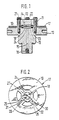
- FIG. 1 shows a longitudinal section through a high-pressure sensor
- FIG. 2 shows a sensor disk.
- the high-pressure sensor has a lower housing part 10, which is closed by a cover 11.
- a cylindrical space 12 or 13 is formed on the opposite end faces of the lower housing part 10 and cover 11, which results in a cylindrical pressure space 14 after the parts have been assembled. From this, a longitudinal bore 15 leads to the outside of the housing, in which a throttle 16 is arranged.
- a round sensor disk 17 which has an inner region 18, which lies in the pressure chamber 14, and a region 19, which lies outside the housing parts.
- FIG. 2 shows, a plurality of openings are formed in the sensor disk 17, through which webs of the cover, not shown, penetrate to the lower housing part, and also a plurality of fastening screws 21 with which the parts are held together.
- the inner area 18 of the sensor disk 17 is sealed off from the outside by sealing rings 22 and 23.
- the disc 17 has a through bore 24 in its center, which creates pressure equalization in the pressure chamber 14.
- the sensor disk 17 expediently consists of steel, on which — as FIG. 2 shows — one or more sensors 25, 26 in the form of piezoresistive sheet resistors are located in the inner region 18.
- the dash-dotted area 27 of the sensor disk represents the sealing area, i. H. the area in which the sealing rings 22, 23 are located.
- Layer conductor tracks 29, 30 lead from the sensors 25, 26 into the outer region 19, in which there are supplementary resistors 31, 32 as well as evaluation circuits and evaluation electronics, connecting plugs etc. for the sensors.
- the resistors and conductor tracks are all very flat and provided with cover layers, which mainly consist of glasses.
- the glasses protect the sensor resistors and the other circuit parts from all environmental influences and produce such a flat, smooth and pressure-resistant surface that a relatively simple and problem-free high-pressure seal is achieved by the sealing rings 22, 23.
- the sensors 25, 26 in the pressure chamber 14 are enclosed on all sides by the pressure medium and respond directly to its pressure changes. In contrast to strain gauges, primary deformation of the disk for signal generation is not necessary here.
- the pressure chamber 14 is acted upon via the bore 15, the throttle 16 serving as a damping throttle.
- the signal generation can be separated from the mechanical coupling of the sensor to the high-pressure chamber. This opens up new degrees of freedom for the development and application of sensor elements and for their constructive use.
- the manufacture of the sensor disk is relatively simple, inexpensive, very reliable and allows the installation of miniaturized sensors in a very small space with many possible installation geometries. It is also possible to easily produce multiple sensors in a confined space. The accuracy and reliability of such sensors can thus be increased even further.
Landscapes
- Physics & Mathematics (AREA)
- General Physics & Mathematics (AREA)
- Measuring Fluid Pressure (AREA)
Description
- Es gibt Sensoren, die nach dem Prinzip der Dehnungsmeßstreifen arbeiten. Bei Hochdrucksensoren führt dies aber zu vielen Problemen, die sich vor allem auf die Langzeitgenauigkeit und die Langzeitstabilität der Sensoren beziehen: Ermüdung der Unterlage, der Einspannung, der Grenzschicht zwischen Dehnungsmeßstreifen und Unterlagen, Ermüdung der elektrischen Kontakte und andere.
- Der erfindungsgemäße Hochdrucksensor nach dem Anspruch 1 hat demgegenüber den Vorteil, daß ein piezoresistives Sensorelement verwendet wird, das direkt auf Druckänderungen des Druckübertragungsmediums anspricht. Damit kann die Signalerzeugung von der mechanischen Ankoppelung des Sensorelements an den Hochdruckraum abgetrennt werden. Dadurch ergeben sich neue Freiheitsgrade für die Bereitstellung von Sensorelementen und für ihren konstruktiven Einsatz, der dadurch sehr flexibel gehandhabt werden kann. Der Hochdrucksensor ist einfach herzustellen, gewährt eine hohe Lebensdauer und stellt eine Scheibe mit ebener Oberfläche dar, so daß er problemlos einzubauen ist.
- Durch die in den abhängigen Ansprüchen aufgeführten Maßnahmen sind Weiterbildungen der im Anspruch 1 angegebenen Merkmale möglich.
- Ein Ausführungsbeispiel der Erfindung ist in der Zeichnung dargestellt und in der nachfolgenden Beschreibung näher erläutert. Es zeigen Figur 1 einen Längsschnitt durch einen Hochdrucksensor, Figur 2 eine Sensorscheibe.
- Der Hochdrucksensor weist ein Gehäuseunterteil 10 auf, das durch einen Deckel 11 verschlossen ist. An den einander gegenüberliegenden Stirnseiten von Gehäuseunterteil 10 und Deckel 11 ist jeweils ein zylindrischer Raum 12 bzw. 13 ausgebildet, wodurch sich nach Zusammenbau der Teile ein zylindrischer Druckraum 14 ergibt. Von diesem führt eine Längsbohrung 15 zum Äußeren des Gehäuses, in der eine Drossel 16 angeordnet ist.
- Zwischen Gehäuseunterteil 10 und Deckel 11 befindet sich eine runde Sensorscheibe 17, die einen inneren Bereich 18 aufweist, welcher im Druckraum 14 liegt, sowie einen Bereich 19, welcher außerhalb der Gehäuseteile liegt. Wie die Figur 2 zeigt, sind in der Sensorscheibe 17 mehrere Durchbrüche ausgebildet, durch welche weiter nicht dargestellte Stege des Deckels zum Gehäuseunterteil hindurchdringen, sowie mehrere Befestigungsschrauben 21, mit welcher die Teile zusammengehalten sind. Der innere Bereich 18 der Sensorscheibe 17 ist durch Dichtringe 22 und 23 nach außen hin abgedichtet. Die Scheibe 17 weist in ihrer Mitte eine durchgehende Bohrung 24 auf, wodurch Druckausgleich im Druckraum 14 geschaffen ist.
- Die Sensorscheibe 17 besteht zweckmäßigerweise aus Stahl, auf der sich - wie Figur 2 zeigt - im inneren Bereich 18 einer oder mehrere Meßfühler 25, 26 in Form piezoresistiver Schichtwiderstände befinden. Der strichpunktierte Bereich 27 der Sensorscheibe stellt den Dichtbereich dar, d. h. den Bereich, in dem die Dichtringe 22, 23 liegen. Von den Meßfühlern 25, 26 führen Schicht-Leiterbahnen 29, 30 in den äußeren Bereich 19, in dem sich Ergänzungswiderstände 31, 32 sowie Auswerteschaltungen und Auswerteelektronik, Anschlußstecker usw. für die Meßfühler befinden. Die Widerstände und Leiterbahnen sind alle sehr flach ausgebildet und mit Deckschichten versehen, die vorwiegend aus Gläsern bestehen. Die Gläser schützen die Sensorwiderstände und die übrigen Schaltungsteile vor allen Umgebungseinflüssen und erzeugen eine so ebene, glatte und druckfeste Oberfläche, daß eine relativ einfache und problemlose Hochdruckabdichtung durch die Dichtringe 22, 23 erzielt wird. Die Meßfühler 25, 26 im Druckraum 14 sind allseitig vom Druckmedium umschlossen und sprechen direkt auf dessen Druckänderungen an. Eine primäre Verformung der Scheibe zur Signalerzeugung ist hier im Gegensatz zu Dehnungsmeßstreifen nicht erforderlich. Der Druckraum 14 wird beaufschlagt über die Bohrung 15, wobei die Drosseln 16 als Dämpfdrossel dient.
- Mit der erfindungsgemäßen Ausbildung kann die Signalerzeugung von der mechanischen Ankopplung des Meßfühlers an den Hochdruckraum getrennt werden. Damit werden neue Freiheitsgrade für die Entwicklung und Anwendung von Sensorelementen und für ihren konstruktiven Einsatz eröffnet. Die Herstellung der Sensorscheibe ist relativ einfach, kostengünstig, sehr zuverlässig und erlaubt den Einbau miniaturisierter Sensoren auf sehr kleinem Raum mit vielen möglichen Einbaugeometrien. Es ist auch eine einfache Herstellung von Mehrfachsensoren auf engstem Raum möglich. Damit kann die Genauigkeit und Zuverlässigkeit solcher Sensoren noch weiter gesteigert werden.
Claims (5)
Applications Claiming Priority (2)
| Application Number | Priority Date | Filing Date | Title |
|---|---|---|---|
| DE19843440568 DE3440568A1 (de) | 1984-11-07 | 1984-11-07 | Hochdrucksensor |
| DE3440568 | 1984-11-07 |
Publications (2)
| Publication Number | Publication Date |
|---|---|
| EP0199772A1 EP0199772A1 (de) | 1986-11-05 |
| EP0199772B1 true EP0199772B1 (de) | 1988-09-21 |
Family
ID=6249652
Family Applications (1)
| Application Number | Title | Priority Date | Filing Date |
|---|---|---|---|
| EP85905392A Expired EP0199772B1 (de) | 1984-11-07 | 1985-10-28 | Hochdrucksensor |
Country Status (5)
| Country | Link |
|---|---|
| US (1) | US4722227A (de) |
| EP (1) | EP0199772B1 (de) |
| JP (1) | JPH0621831B2 (de) |
| DE (2) | DE3440568A1 (de) |
| WO (1) | WO1986002999A1 (de) |
Families Citing this family (16)
| Publication number | Priority date | Publication date | Assignee | Title |
|---|---|---|---|---|
| IT206925Z2 (it) * | 1986-03-10 | 1987-10-19 | Marelli Autronica | Sensore a filo spesso in particolare sensore di pressione |
| FR2601133B1 (fr) * | 1986-07-01 | 1990-05-11 | Beta Sa | Dispositif de mesure des pressions et notamment des hautes pressions |
| IT1223710B (it) * | 1988-07-21 | 1990-09-29 | Marelli Autronica | Trasduttore di altissima pressione in particolare per il rilevamento della pressione di un fluido idraulico |
| DE3843604A1 (de) * | 1988-12-23 | 1990-06-28 | Inst Fiz Vysokich Davlenij Im | Hochdruckzelle |
| US4939497A (en) * | 1989-04-18 | 1990-07-03 | Nippon Soken, Inc. | Pressure sensor |
| US5728942A (en) * | 1995-11-28 | 1998-03-17 | Boger; Henry W. | Fluid pressure measuring system for control valves |
| US5955677A (en) * | 1997-01-22 | 1999-09-21 | Geophysical Research Corporation | Metal seal for pressure transducer |
| NO308228B1 (no) * | 1997-11-26 | 2000-08-14 | Presens As | Dynamisk trykksensor |
| DE10034460A1 (de) * | 2000-07-15 | 2002-01-31 | Bosch Gmbh Robert | Hochdrucksensor, Verfahren und Werkzeug zu seiner Herstellung |
| DE10333438A1 (de) * | 2003-07-23 | 2005-02-17 | Robert Bosch Gmbh | Brennraumdrucksensor mit Metallmembran mit piezoresistiver Metalldünnschicht |
| DE102004025339B4 (de) * | 2004-05-19 | 2007-09-06 | Ifm Electronic Gmbh | Drucksensor |
| US7400042B2 (en) * | 2005-05-03 | 2008-07-15 | Rosemount Aerospace Inc. | Substrate with adhesive bonding metallization with diffusion barrier |
| US20070013014A1 (en) * | 2005-05-03 | 2007-01-18 | Shuwen Guo | High temperature resistant solid state pressure sensor |
| US7628309B1 (en) * | 2005-05-03 | 2009-12-08 | Rosemount Aerospace Inc. | Transient liquid phase eutectic bonding |
| US7538401B2 (en) | 2005-05-03 | 2009-05-26 | Rosemount Aerospace Inc. | Transducer for use in harsh environments |
| CN113658700B (zh) * | 2021-08-16 | 2023-10-27 | 复旦大学附属中山医院 | 一种基于机器学习的门脉高压无创评估方法及系统 |
Family Cites Families (10)
| Publication number | Priority date | Publication date | Assignee | Title |
|---|---|---|---|---|
| GB981793A (en) * | 1960-06-20 | 1965-01-27 | Coal Industry Patents Ltd | Improvements in or relating to means for ascertaining fluid pressure |
| GB966527A (en) * | 1960-06-28 | 1964-08-12 | Jack Sidney Dean | Electro-mechanical transducer |
| DE1932899A1 (de) * | 1969-06-28 | 1971-01-07 | Rohrbach Dr Christof | Messwertgeber zum Umwandeln von Kraeften,mechanischen Spannungen oder Druecken in elektrische Widerstandsaenderungen |
| DE2130390A1 (de) * | 1971-06-18 | 1972-12-21 | Siemens Ag | Druckmessgeraet |
| JPS5618984Y2 (de) * | 1972-07-28 | 1981-05-06 | ||
| JPS542143Y2 (de) * | 1972-07-28 | 1979-01-29 | ||
| US4068206A (en) * | 1976-06-25 | 1978-01-10 | Midland-Ross Corporation | Pressure-sensing semiconductor transducer |
| JPS581548B2 (ja) * | 1977-03-17 | 1983-01-11 | 株式会社横河電機製作所 | 薄膜ストレンゲ−ジ変換器 |
| DE3125640A1 (de) * | 1981-06-30 | 1983-01-13 | Robert Bosch Gmbh, 7000 Stuttgart | Sensor |
| US4586018A (en) * | 1983-09-19 | 1986-04-29 | Ford Motor Company | Combustion pressure sensor |
-
1984
- 1984-11-07 DE DE19843440568 patent/DE3440568A1/de not_active Withdrawn
-
1985
- 1985-10-28 JP JP60504849A patent/JPH0621831B2/ja not_active Expired - Lifetime
- 1985-10-28 EP EP85905392A patent/EP0199772B1/de not_active Expired
- 1985-10-28 WO PCT/DE1985/000418 patent/WO1986002999A1/de not_active Ceased
- 1985-10-28 DE DE8585905392T patent/DE3565179D1/de not_active Expired
- 1985-10-28 US US06/887,133 patent/US4722227A/en not_active Expired - Fee Related
Also Published As
| Publication number | Publication date |
|---|---|
| US4722227A (en) | 1988-02-02 |
| JPS62500737A (ja) | 1987-03-26 |
| DE3565179D1 (en) | 1988-10-27 |
| JPH0621831B2 (ja) | 1994-03-23 |
| DE3440568A1 (de) | 1986-05-15 |
| WO1986002999A1 (fr) | 1986-05-22 |
| EP0199772A1 (de) | 1986-11-05 |
Similar Documents
| Publication | Publication Date | Title |
|---|---|---|
| EP0199772B1 (de) | Hochdrucksensor | |
| DE69011551T2 (de) | Konsumdirektdrucksensoreinheit. | |
| DE3787651T2 (de) | Vom medium isolierte sensoren für druck. | |
| DE4335588C2 (de) | Drucksensor | |
| DE102007003446B4 (de) | Montagestruktur eines Drucksensorelements | |
| DE69422851T2 (de) | Membran-Druckwandler mit einer Stossschutzvorrichtung und Dichtemessgerät mit einem solchen Wandler | |
| DE102004041388A1 (de) | Drucksensorzelle und diese verwendende Drucksensorvorrichtung | |
| DE10252023B3 (de) | Drucksensor | |
| DE2755306A1 (de) | Druckwandler | |
| DE2848856A1 (de) | Kapazitiver druckwandler | |
| EP1269134A1 (de) | Sensoranordnung | |
| DE3713236C2 (de) | ||
| DE69006925T2 (de) | Hochdruckwandler. | |
| DE10130375B4 (de) | Differenzdrucksensor | |
| DE69410061T3 (de) | Flüssigkeitsmessvorrichtung | |
| DE102019131267A1 (de) | Dichtungsanordnung und Dichtelement | |
| DE4111118A1 (de) | Mikromechanischer kapazitiver druckwandler | |
| EP0115074B1 (de) | Druckdifferenz-Messeinrichtung | |
| DE3341353C2 (de) | ||
| DE102005020345A1 (de) | Dichtungsstruktur für einen Verbinder | |
| DE10130376B4 (de) | Differenzdrucksensor | |
| DE102004051219B4 (de) | Druckmessaufnehmer | |
| DE3610351A1 (de) | Drucksensor | |
| DE8908951U1 (de) | Drucksensor | |
| DE102019130571A1 (de) | Drucksensor zur Bestimmung des Drucks eines Prozessmediums |
Legal Events
| Date | Code | Title | Description |
|---|---|---|---|
| PUAI | Public reference made under article 153(3) epc to a published international application that has entered the european phase |
Free format text: ORIGINAL CODE: 0009012 |
|
| 17P | Request for examination filed |
Effective date: 19860605 |
|
| AK | Designated contracting states |
Kind code of ref document: A1 Designated state(s): DE FR GB IT SE |
|
| 17Q | First examination report despatched |
Effective date: 19871007 |
|
| GRAA | (expected) grant |
Free format text: ORIGINAL CODE: 0009210 |
|
| AK | Designated contracting states |
Kind code of ref document: B1 Designated state(s): DE FR GB IT SE |
|
| GBT | Gb: translation of ep patent filed (gb section 77(6)(a)/1977) | ||
| REF | Corresponds to: |
Ref document number: 3565179 Country of ref document: DE Date of ref document: 19881027 |
|
| ET | Fr: translation filed | ||
| ITF | It: translation for a ep patent filed | ||
| PLBE | No opposition filed within time limit |
Free format text: ORIGINAL CODE: 0009261 |
|
| STAA | Information on the status of an ep patent application or granted ep patent |
Free format text: STATUS: NO OPPOSITION FILED WITHIN TIME LIMIT |
|
| 26N | No opposition filed | ||
| REG | Reference to a national code |
Ref country code: GB Ref legal event code: 746 |
|
| ITTA | It: last paid annual fee | ||
| ITPR | It: changes in ownership of a european patent |
Owner name: OFFERTA DI LICENZA AL PUBBLICO |
|
| REG | Reference to a national code |
Ref country code: FR Ref legal event code: DL |
|
| PGFP | Annual fee paid to national office [announced via postgrant information from national office to epo] |
Ref country code: GB Payment date: 19941018 Year of fee payment: 10 |
|
| PGFP | Annual fee paid to national office [announced via postgrant information from national office to epo] |
Ref country code: SE Payment date: 19941021 Year of fee payment: 10 |
|
| PGFP | Annual fee paid to national office [announced via postgrant information from national office to epo] |
Ref country code: FR Payment date: 19941028 Year of fee payment: 10 |
|
| PGFP | Annual fee paid to national office [announced via postgrant information from national office to epo] |
Ref country code: DE Payment date: 19941222 Year of fee payment: 10 |
|
| EAL | Se: european patent in force in sweden |
Ref document number: 85905392.8 |
|
| PG25 | Lapsed in a contracting state [announced via postgrant information from national office to epo] |
Ref country code: GB Effective date: 19951028 |
|
| PG25 | Lapsed in a contracting state [announced via postgrant information from national office to epo] |
Ref country code: SE Effective date: 19951029 |
|
| GBPC | Gb: european patent ceased through non-payment of renewal fee |
Effective date: 19951028 |
|
| PG25 | Lapsed in a contracting state [announced via postgrant information from national office to epo] |
Ref country code: FR Effective date: 19960628 |
|
| EUG | Se: european patent has lapsed |
Ref document number: 85905392.8 |
|
| PG25 | Lapsed in a contracting state [announced via postgrant information from national office to epo] |
Ref country code: DE Effective date: 19960702 |
|
| REG | Reference to a national code |
Ref country code: FR Ref legal event code: ST |