EP0199850A2 - Dispositif pour le collage mutuel de particules ramollissant thermiquement pour former un corps plastique - Google Patents
Dispositif pour le collage mutuel de particules ramollissant thermiquement pour former un corps plastique Download PDFInfo
- Publication number
- EP0199850A2 EP0199850A2 EP85115974A EP85115974A EP0199850A2 EP 0199850 A2 EP0199850 A2 EP 0199850A2 EP 85115974 A EP85115974 A EP 85115974A EP 85115974 A EP85115974 A EP 85115974A EP 0199850 A2 EP0199850 A2 EP 0199850A2
- Authority
- EP
- European Patent Office
- Prior art keywords
- piston
- particles
- flow
- movement
- gas
- Prior art date
- Legal status (The legal status is an assumption and is not a legal conclusion. Google has not performed a legal analysis and makes no representation as to the accuracy of the status listed.)
- Granted
Links
Images
Classifications
-
- B—PERFORMING OPERATIONS; TRANSPORTING
- B29—WORKING OF PLASTICS; WORKING OF SUBSTANCES IN A PLASTIC STATE IN GENERAL
- B29C—SHAPING OR JOINING OF PLASTICS; SHAPING OF MATERIAL IN A PLASTIC STATE, NOT OTHERWISE PROVIDED FOR; AFTER-TREATMENT OF THE SHAPED PRODUCTS, e.g. REPAIRING
- B29C43/00—Compression moulding, i.e. applying external pressure to flow the moulding material; Apparatus therefor
- B29C43/32—Component parts, details or accessories; Auxiliary operations
- B29C43/52—Heating or cooling
-
- B—PERFORMING OPERATIONS; TRANSPORTING
- B29—WORKING OF PLASTICS; WORKING OF SUBSTANCES IN A PLASTIC STATE IN GENERAL
- B29C—SHAPING OR JOINING OF PLASTICS; SHAPING OF MATERIAL IN A PLASTIC STATE, NOT OTHERWISE PROVIDED FOR; AFTER-TREATMENT OF THE SHAPED PRODUCTS, e.g. REPAIRING
- B29C35/00—Heating, cooling or curing, e.g. crosslinking or vulcanising; Apparatus therefor
- B29C35/02—Heating or curing, e.g. crosslinking or vulcanizing during moulding, e.g. in a mould
- B29C35/04—Heating or curing, e.g. crosslinking or vulcanizing during moulding, e.g. in a mould using liquids, gas or steam
-
- B—PERFORMING OPERATIONS; TRANSPORTING
- B29—WORKING OF PLASTICS; WORKING OF SUBSTANCES IN A PLASTIC STATE IN GENERAL
- B29C—SHAPING OR JOINING OF PLASTICS; SHAPING OF MATERIAL IN A PLASTIC STATE, NOT OTHERWISE PROVIDED FOR; AFTER-TREATMENT OF THE SHAPED PRODUCTS, e.g. REPAIRING
- B29C43/00—Compression moulding, i.e. applying external pressure to flow the moulding material; Apparatus therefor
- B29C43/006—Pressing and sintering powders, granules or fibres
-
- B—PERFORMING OPERATIONS; TRANSPORTING
- B29—WORKING OF PLASTICS; WORKING OF SUBSTANCES IN A PLASTIC STATE IN GENERAL
- B29C—SHAPING OR JOINING OF PLASTICS; SHAPING OF MATERIAL IN A PLASTIC STATE, NOT OTHERWISE PROVIDED FOR; AFTER-TREATMENT OF THE SHAPED PRODUCTS, e.g. REPAIRING
- B29C67/00—Shaping techniques not covered by groups B29C39/00 - B29C65/00, B29C70/00 or B29C73/00
- B29C67/02—Moulding by agglomerating
- B29C67/04—Sintering
-
- B—PERFORMING OPERATIONS; TRANSPORTING
- B29—WORKING OF PLASTICS; WORKING OF SUBSTANCES IN A PLASTIC STATE IN GENERAL
- B29C—SHAPING OR JOINING OF PLASTICS; SHAPING OF MATERIAL IN A PLASTIC STATE, NOT OTHERWISE PROVIDED FOR; AFTER-TREATMENT OF THE SHAPED PRODUCTS, e.g. REPAIRING
- B29C33/00—Moulds or cores; Details thereof or accessories therefor
- B29C33/20—Opening, closing or clamping
-
- B—PERFORMING OPERATIONS; TRANSPORTING
- B29—WORKING OF PLASTICS; WORKING OF SUBSTANCES IN A PLASTIC STATE IN GENERAL
- B29C—SHAPING OR JOINING OF PLASTICS; SHAPING OF MATERIAL IN A PLASTIC STATE, NOT OTHERWISE PROVIDED FOR; AFTER-TREATMENT OF THE SHAPED PRODUCTS, e.g. REPAIRING
- B29C35/00—Heating, cooling or curing, e.g. crosslinking or vulcanising; Apparatus therefor
- B29C35/02—Heating or curing, e.g. crosslinking or vulcanizing during moulding, e.g. in a mould
- B29C35/04—Heating or curing, e.g. crosslinking or vulcanizing during moulding, e.g. in a mould using liquids, gas or steam
- B29C35/045—Heating or curing, e.g. crosslinking or vulcanizing during moulding, e.g. in a mould using liquids, gas or steam using gas or flames
-
- B—PERFORMING OPERATIONS; TRANSPORTING
- B29—WORKING OF PLASTICS; WORKING OF SUBSTANCES IN A PLASTIC STATE IN GENERAL
- B29K—INDEXING SCHEME ASSOCIATED WITH SUBCLASSES B29B, B29C OR B29D, RELATING TO MOULDING MATERIALS OR TO MATERIALS FOR MOULDS, REINFORCEMENTS, FILLERS OR PREFORMED PARTS, e.g. INSERTS
- B29K2105/00—Condition, form or state of moulded material or of the material to be shaped
- B29K2105/04—Condition, form or state of moulded material or of the material to be shaped cellular or porous
-
- B—PERFORMING OPERATIONS; TRANSPORTING
- B29—WORKING OF PLASTICS; WORKING OF SUBSTANCES IN A PLASTIC STATE IN GENERAL
- B29K—INDEXING SCHEME ASSOCIATED WITH SUBCLASSES B29B, B29C OR B29D, RELATING TO MOULDING MATERIALS OR TO MATERIALS FOR MOULDS, REINFORCEMENTS, FILLERS OR PREFORMED PARTS, e.g. INSERTS
- B29K2105/00—Condition, form or state of moulded material or of the material to be shaped
- B29K2105/25—Solid
- B29K2105/251—Particles, powder or granules
Definitions
- the invention relates to a device for the mutual bonding of thermally softenable particles to a plastic body, comprising a molding tool with gas-permeable walls into which the particles can be introduced in bulk, means for compressing the particles and means for producing a penetrating the molding tool and the bed contained therein Flow from a heated gas.
- GB-PS 1 578 045 refers to a device of the aforementioned type. It essentially consists of two sieve belts which are guided parallel to one another and compress a bed of thermally softenable particles to form a layer and are passed transversely through a nozzle dryer.
- the latter comprises a circular, self-contained wind tunnel in which the air volume contained is heated by heating elements and set in motion by fans.
- the molding tool formed from the two sieve belts is thereby always flowed through in the same direction, which leads to the fact that the thermally softenable particles contained in the formed part are sintered differently well in the region of both surfaces.
- the molded part not only has a different smoothness in the area of both surfaces, but also has an asymmetrical structure in its cross section. The use of a corresponding molded part as a construction element is therefore problematic.
- the invention has for its object to develop a device of the type mentioned in such a way that with reduced investment volume arbitrarily designed plastic body of improved quality can be obtained.
- the molding tool is designed as a piston, that the piston is stored in a closable space bounded by end walls and containing the gas, that the piston seals against the surrounding walls of the room and is movable back and forth between the end walls and that the means for generating the flow consist of moving means moving the pistons.
- the subclaims refer to advantageous embodiments.
- the heating of the particles to the sintering temperature takes place in the device according to the invention as well as in that according to the prior art by forcing a certain volume of heated gas through the spaces between the individual particles.
- the basis for this process is not an artificially generated movement of the gas, which remains at rest in the space enclosed by the end walls and the surrounding walls, but the reciprocating movement of the piston containing the molding tool between the end walls of the space.
- the device according to the invention can be designed to be significantly smaller and less expensive than the embodiment described at the outset.
- the molding tool contained in the piston in the device according to the invention is flowed through from both sides in the same way during the reciprocating movement of the piston.
- the sintering conditions are absolutely identical in the area of both sides, which makes it easier to use the molded part obtained as a structural element.
- the device shown is suitable for producing molded parts of any shape from thermally softenable plastic particles, but is particularly suitable for producing flat products, such as, for example, a headliner or interior trim for a motor vehicle. In this case, excellent values of great continuity can be achieved both statically and acoustically.
- the space in which the piston can be moved back and forth should be easily accessible in order to enable easy loading and unloading of the molding tool.
- the piston is expediently loaded in a position approximating the end wall mentioned.
- the special design of the mold cavity in the piston depends on the type of thermally softenable particles to be processed. These can consist, for example, of a non-foamed or a fully foamed, thermally softenable material, which requires the size of the mold cavity to be reduced following the thermal softening of at least the surfaces of the particles in order to achieve sufficient mutual compression.
- the mold cavity can be delimited in a region by a partial piston which can be advanced independently of the movement of the piston in the direction of the mold cavity.
- the drive means can be formed by simple spring bodies.
- the molded parts obtained are characterized by a particularly high surface quality. They can be varied in many ways from a design point of view.
- the piston can be moved back and forth by hand, since surprisingly neither a particularly large piston stroke nor a particularly high movement speed is required.
- the reciprocating movement is carried out with great uniformity both in terms of speed and in terms of stroke.
- the means for the reciprocating movement of the piston are driven by a motor. Good balancing of the movement means makes it easier to avoid unwanted vibrations.
- the sintering conditions of the particles can be varied particularly easily in an embodiment in which the partial spaces delimiting the pistons on both sides are connected by an overflow channel with a constricting flow cross-section.
- a change in the flow cross section in this case results in a change in the gas volume pressed through the spaces between the particles, which is possible regardless of the change in the speed of movement and / or the stroke of the piston.
- the overflow channel in such a way that the flow cross section is larger in one flow direction than in the other.
- the sintering conditions of the particles differ accordingly and give the finished molded part a targeted asymmetrical cross section.
- a corresponding profile design can, however, also be achieved with a device in which the piston can be moved faster in one direction of movement than in the other.
- the design is generally somewhat more complex than that described above. However, it works almost noiselessly, which is also remarkable.
- the piston of the device according to the invention is sealed off from the surrounding walls by a narrow gap or conventional piston sealant.
- a narrow gap or conventional piston sealant Various possibilities are known to the person skilled in the art in this regard, and it has proven expedient to separate the actual seal from the guide, in particular in the case of designs in which very large-sized workpieces have to be produced, such as, for example, an average headliner with an area of approximately 1. 8 m 2 .
- a gas can flow through the mold cavity contained in the piston. It accordingly consists of a sieve or perforated plate with an open area proportion of at least 40 S. To achieve the required stiffness, it has proven to be advantageous if the perforated plate or sieve designed according to the finished part is removed on a supporting structure, for example one honeycomb-like skeleton structure or a rib construction.
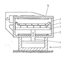
- the piston is sealed off from the surrounding walls of the room 2 by felt strips and is mounted on a transverse yoke 3, which in turn is connected to the piston rod 4 of the pneumatic drive 5.
- the subspaces adjacent to the pistons on the upper and lower sides each contain a heating device 6 in the form of an oil radiator.
- the air volume contained has an average temperature of 260 ° C 5 seconds after the upper end wall has been closed.
- the piston By actuating the drive 5, the piston is then set in a vertical reciprocating movement, the stroke being dimensioned such that the piston alternately almost reaches the two end walls of the space 2.
- the heated air flows through the spaces between the particles in an alternating direction, causing the particles to heat up quickly.
- the blowing agent still contained leads to a considerable increase in the volume of the particles and in this connection to a strong mutual compression with one another and with the inner wall of the mold cavity.
- the piston for removing the finished workpiece is raised as far as possible after removal of the upper end wall.
- the entire volume of heated air is in this case below the piston, while cold air can flow against the top of the piston. This accelerates the cooling of the finished workpiece. It can be further accelerated by introducing compressed air into the area between the lower piston part and the finished workpiece. Since the subspace adjoining the piston on the underside is closed on all sides, this air can only escape upwards. Appropriate supply of cold compressed air is therefore ideally suited to dissipating excess heat quickly and inexpensively.
Landscapes
- Engineering & Computer Science (AREA)
- Mechanical Engineering (AREA)
- Physics & Mathematics (AREA)
- Health & Medical Sciences (AREA)
- Oral & Maxillofacial Surgery (AREA)
- Thermal Sciences (AREA)
- Casting Or Compression Moulding Of Plastics Or The Like (AREA)
- Processing And Handling Of Plastics And Other Materials For Molding In General (AREA)
- Manufacture Of Porous Articles, And Recovery And Treatment Of Waste Products (AREA)
- Molding Of Porous Articles (AREA)
- Moulds For Moulding Plastics Or The Like (AREA)
Applications Claiming Priority (2)
| Application Number | Priority Date | Filing Date | Title |
|---|---|---|---|
| DE3514022A DE3514022C1 (de) | 1985-04-18 | 1985-04-18 | Vorrichtung zum gegenseitigen Verkleben thermisch erweichbarer Partikel zu einem Kunststoffkoerper |
| DE3514022 | 1985-04-18 |
Publications (3)
| Publication Number | Publication Date |
|---|---|
| EP0199850A2 true EP0199850A2 (fr) | 1986-11-05 |
| EP0199850A3 EP0199850A3 (en) | 1987-10-28 |
| EP0199850B1 EP0199850B1 (fr) | 1989-03-08 |
Family
ID=6268480
Family Applications (1)
| Application Number | Title | Priority Date | Filing Date |
|---|---|---|---|
| EP85115974A Expired EP0199850B1 (fr) | 1985-04-18 | 1985-12-14 | Dispositif pour le collage mutuel de particules ramollissant thermiquement pour former un corps plastique |
Country Status (4)
| Country | Link |
|---|---|
| US (1) | US4689004A (fr) |
| EP (1) | EP0199850B1 (fr) |
| JP (1) | JPS61244531A (fr) |
| DE (2) | DE3514022C1 (fr) |
Families Citing this family (14)
| Publication number | Priority date | Publication date | Assignee | Title |
|---|---|---|---|---|
| JPH049143Y2 (fr) * | 1986-04-11 | 1992-03-06 | ||
| DE3637905A1 (de) * | 1986-11-06 | 1988-05-19 | Werner Dipl Ing Dr Neu | Verfahren und vorrichtung zur herstellung von gegenstaenden aus thermoplastischem kunststoff |
| DE4019632C2 (de) * | 1990-06-20 | 1996-12-19 | Tetra Pak Gmbh | Vorrichtung zum Erhitzen von plattenförmigen Teilen aus tiefziehfähigem Kunststoff |
| US5391337A (en) * | 1991-06-24 | 1995-02-21 | Ford Motor Company | Method for making evaporative casting patterns |
| US5441675A (en) * | 1993-11-01 | 1995-08-15 | Davidson Textron, Inc. | Forming method and apparatus |
| US5741455A (en) * | 1995-12-08 | 1998-04-21 | Purdue Research Foundation | Inert gas heated compression molding process and apparatus |
| US7019819B2 (en) | 2002-11-13 | 2006-03-28 | Molecular Imprints, Inc. | Chucking system for modulating shapes of substrates |
| US7641840B2 (en) * | 2002-11-13 | 2010-01-05 | Molecular Imprints, Inc. | Method for expelling gas positioned between a substrate and a mold |
| US7090716B2 (en) * | 2003-10-02 | 2006-08-15 | Molecular Imprints, Inc. | Single phase fluid imprint lithography method |
| AU2006284541B2 (en) * | 2005-08-26 | 2011-02-17 | Quickstep Technologies Pty Ltd | Reticulation system for composite component production |
| US7316554B2 (en) * | 2005-09-21 | 2008-01-08 | Molecular Imprints, Inc. | System to control an atmosphere between a body and a substrate |
| CN101405087A (zh) * | 2006-04-03 | 2009-04-08 | 分子制模股份有限公司 | 光刻印刷系统 |
| US8215946B2 (en) | 2006-05-18 | 2012-07-10 | Molecular Imprints, Inc. | Imprint lithography system and method |
| US20100096764A1 (en) * | 2008-10-20 | 2010-04-22 | Molecular Imprints, Inc. | Gas Environment for Imprint Lithography |
Family Cites Families (6)
| Publication number | Priority date | Publication date | Assignee | Title |
|---|---|---|---|---|
| CH514415A (de) * | 1969-08-15 | 1971-10-31 | Polygest Ag | Verfahren zur homogenen Verteilung eines Pulvers und nachfolgender Verformung sowie Vorrichtung zur Ausführung des Verfahrens |
| DE2119358A1 (en) * | 1971-04-21 | 1972-11-02 | Müller, Othmar, 6209 Aarbergen | Thermally insulating building structures - by filling cavities with foam polystyrene at site |
| FR2225270A1 (en) * | 1973-04-12 | 1974-11-08 | Ducruez Raymond | Moulding deep containers from expanded polystyrene - using a coaxial thrust plate to consolidate the beads |
| DE7631952U1 (de) * | 1976-10-13 | 1977-04-07 | Fa. Carl Freudenberg, 6940 Weinheim | Drainageplatte |
| JPS5947976B2 (ja) * | 1979-02-15 | 1984-11-22 | 積水化成品工業株式会社 | 発泡成形型 |
| US4492663A (en) * | 1982-01-11 | 1985-01-08 | Reinfeld Nyles V | Method and adjustable length mold for manufacturing a foamed packaging assembly |
-
1985
- 1985-04-18 DE DE3514022A patent/DE3514022C1/de not_active Expired
- 1985-12-14 DE DE8585115974T patent/DE3568548D1/de not_active Expired
- 1985-12-14 EP EP85115974A patent/EP0199850B1/fr not_active Expired
-
1986
- 1986-03-14 US US06/840,401 patent/US4689004A/en not_active Expired - Fee Related
- 1986-04-16 JP JP61087845A patent/JPS61244531A/ja active Granted
Also Published As
| Publication number | Publication date |
|---|---|
| DE3568548D1 (en) | 1989-04-13 |
| JPS61244531A (ja) | 1986-10-30 |
| US4689004A (en) | 1987-08-25 |
| EP0199850B1 (fr) | 1989-03-08 |
| JPH0450895B2 (fr) | 1992-08-17 |
| DE3514022C1 (de) | 1986-07-10 |
| EP0199850A3 (en) | 1987-10-28 |
Similar Documents
| Publication | Publication Date | Title |
|---|---|---|
| EP0199850B1 (fr) | Dispositif pour le collage mutuel de particules ramollissant thermiquement pour former un corps plastique | |
| DE3708006A1 (de) | Verfahren zum herstellen von hohlkoerpern aus thermoplastischem kunststoff mit einer mehrschichtigen wandung | |
| EP0575771A1 (fr) | Panneau en matière cellulaire, en particulier pièce façonnée d'une ou plusieurs plaques en matière cellulaire | |
| DE3040694C2 (fr) | ||
| DE2600144A1 (de) | Verfahren und vorrichtung zum kontinuierlichen formen von gegenstaenden mit dreidimensionalen mustern und oberflaechenstrukturen aus thermoplastischen polymeren werkstoffen | |
| DE1289983B (de) | Verfahren und Vorrichtung zum Herstellen hohler Gegenstaende aus thermoplastischem Kunststoff | |
| EP0412931A1 (fr) | Procédé de fabrication d'un corps céramique poreux | |
| EP0559097A2 (fr) | Procédé pour la préparation d'une mousse métallique | |
| DE1704313A1 (de) | Verfahren und Vorrichtung zum Formen hohler Erzeugnisse | |
| DE2256078A1 (de) | Verfahren und vorrichtung zum ausformen einer nahrungsmittelmasse | |
| DE3343210C1 (de) | Verfahren und Vorrichtung zur Herstellung verdichteter Formkoerper | |
| DE1901828A1 (de) | Verfahren und Vorrichtungen zum Herstellen von Schaumstoff-Verbundkoerpern | |
| DE2341139A1 (de) | Verfahren und vorrichtung zur herstellung von gegenstaenden | |
| DE19744300B4 (de) | Verfahren zur Herstellung von Poren aufweisenden Formkörpern bzw. Werkstücken auf Basis von (Leicht-)Metallen, deren Herstellung und deren Verwendung | |
| DE2236585A1 (de) | Verfahren und vorrichtung zur herstellung eines heissgepressten teiles | |
| DE202006009569U1 (de) | Vorrichtung zur Herstellung von Formteilen aus Schaumstoff-Partikeln | |
| DE102016225124A1 (de) | Vorrichtung zur dreidimensionalen Formgebung, Steuerungsverfahren für eine Vorrichtung zur dreidimensionalen Formgebung, Herstellungsverfahren für dreidimensional geformte Objekte, Programm und Speichermedium | |
| DE3429141C2 (de) | Verfahren zur Herstellung eines Hohlkörpers | |
| EP0251989A2 (fr) | Cadre de fixation desserrable pour le blocage d'une feuille | |
| EP0600240A1 (fr) | Méthode pour améliorer l'isolation de menuiserie en profilés en écarteurs isolant | |
| DE4115609C1 (fr) | ||
| DE3633919C1 (en) | Process and mould for producing upholsteries provided with foam-backed coverings, in particular upholsteries for car seats | |
| DE2423503C3 (de) | Vorrichtung zum Herstellen von Hohlkörpern aus thermoplastischem Kunststoff | |
| DE2415594A1 (de) | Schneidemaschine, insbesondere formschneidemaschine fuer schaumstoffe | |
| EP0477590A2 (fr) | Procédé et dispositif pour la fabrication d'articles en forme de colonne |
Legal Events
| Date | Code | Title | Description |
|---|---|---|---|
| PUAI | Public reference made under article 153(3) epc to a published international application that has entered the european phase |
Free format text: ORIGINAL CODE: 0009012 |
|
| AK | Designated contracting states |
Kind code of ref document: A2 Designated state(s): DE FR GB SE |
|
| PUAL | Search report despatched |
Free format text: ORIGINAL CODE: 0009013 |
|
| AK | Designated contracting states |
Kind code of ref document: A3 Designated state(s): DE FR GB SE |
|
| 17P | Request for examination filed |
Effective date: 19870911 |
|
| 17Q | First examination report despatched |
Effective date: 19880125 |
|
| GRAA | (expected) grant |
Free format text: ORIGINAL CODE: 0009210 |
|
| AK | Designated contracting states |
Kind code of ref document: B1 Designated state(s): DE FR GB SE |
|
| REF | Corresponds to: |
Ref document number: 3568548 Country of ref document: DE Date of ref document: 19890413 |
|
| ET | Fr: translation filed | ||
| GBT | Gb: translation of ep patent filed (gb section 77(6)(a)/1977) | ||
| PLBE | No opposition filed within time limit |
Free format text: ORIGINAL CODE: 0009261 |
|
| STAA | Information on the status of an ep patent application or granted ep patent |
Free format text: STATUS: NO OPPOSITION FILED WITHIN TIME LIMIT |
|
| 26N | No opposition filed | ||
| EAL | Se: european patent in force in sweden |
Ref document number: 85115974.9 |
|
| PGFP | Annual fee paid to national office [announced via postgrant information from national office to epo] |
Ref country code: SE Payment date: 19961125 Year of fee payment: 12 |
|
| PGFP | Annual fee paid to national office [announced via postgrant information from national office to epo] |
Ref country code: GB Payment date: 19961129 Year of fee payment: 12 |
|
| PGFP | Annual fee paid to national office [announced via postgrant information from national office to epo] |
Ref country code: FR Payment date: 19961203 Year of fee payment: 12 |
|
| PGFP | Annual fee paid to national office [announced via postgrant information from national office to epo] |
Ref country code: DE Payment date: 19961205 Year of fee payment: 12 |
|
| PG25 | Lapsed in a contracting state [announced via postgrant information from national office to epo] |
Ref country code: DE Effective date: 19971031 |
|
| PG25 | Lapsed in a contracting state [announced via postgrant information from national office to epo] |
Ref country code: GB Free format text: LAPSE BECAUSE OF NON-PAYMENT OF DUE FEES Effective date: 19971214 |
|
| PG25 | Lapsed in a contracting state [announced via postgrant information from national office to epo] |
Ref country code: SE Free format text: LAPSE BECAUSE OF NON-PAYMENT OF DUE FEES Effective date: 19971215 |
|
| PG25 | Lapsed in a contracting state [announced via postgrant information from national office to epo] |
Ref country code: FR Free format text: THE PATENT HAS BEEN ANNULLED BY A DECISION OF A NATIONAL AUTHORITY Effective date: 19971231 |
|
| GBPC | Gb: european patent ceased through non-payment of renewal fee |
Effective date: 19971214 |
|
| EUG | Se: european patent has lapsed |
Ref document number: 85115974.9 |
|
| REG | Reference to a national code |
Ref country code: FR Ref legal event code: ST |