EP0200010A1 - Zündanlage - Google Patents
Zündanlage Download PDFInfo
- Publication number
- EP0200010A1 EP0200010A1 EP86104406A EP86104406A EP0200010A1 EP 0200010 A1 EP0200010 A1 EP 0200010A1 EP 86104406 A EP86104406 A EP 86104406A EP 86104406 A EP86104406 A EP 86104406A EP 0200010 A1 EP0200010 A1 EP 0200010A1
- Authority
- EP
- European Patent Office
- Prior art keywords
- voltage
- ignition
- spark gap
- medium
- storage capacitor
- Prior art date
- Legal status (The legal status is an assumption and is not a legal conclusion. Google has not performed a legal analysis and makes no representation as to the accuracy of the status listed.)
- Granted
Links
- 239000003990 capacitor Substances 0.000 claims abstract description 40
- 230000000903 blocking effect Effects 0.000 claims description 9
- 238000011084 recovery Methods 0.000 claims 1
- 230000008054 signal transmission Effects 0.000 claims 1
- 230000015556 catabolic process Effects 0.000 abstract description 4
- 239000007789 gas Substances 0.000 description 5
- 239000000203 mixture Substances 0.000 description 4
- LFQSCWFLJHTTHZ-UHFFFAOYSA-N Ethanol Chemical compound CCO LFQSCWFLJHTTHZ-UHFFFAOYSA-N 0.000 description 3
- 230000003197 catalytic effect Effects 0.000 description 3
- 238000010586 diagram Methods 0.000 description 3
- 238000004146 energy storage Methods 0.000 description 3
- 239000000446 fuel Substances 0.000 description 3
- ATUOYWHBWRKTHZ-UHFFFAOYSA-N Propane Chemical compound CCC ATUOYWHBWRKTHZ-UHFFFAOYSA-N 0.000 description 2
- 239000011162 core material Substances 0.000 description 2
- 239000001257 hydrogen Substances 0.000 description 2
- 229910052739 hydrogen Inorganic materials 0.000 description 2
- 239000012212 insulator Substances 0.000 description 2
- VNWKTOKETHGBQD-UHFFFAOYSA-N methane Chemical compound C VNWKTOKETHGBQD-UHFFFAOYSA-N 0.000 description 2
- 238000000034 method Methods 0.000 description 2
- 238000004804 winding Methods 0.000 description 2
- 241001136792 Alle Species 0.000 description 1
- UFHFLCQGNIYNRP-UHFFFAOYSA-N Hydrogen Chemical compound [H][H] UFHFLCQGNIYNRP-UHFFFAOYSA-N 0.000 description 1
- 230000003321 amplification Effects 0.000 description 1
- 230000005540 biological transmission Effects 0.000 description 1
- 239000003985 ceramic capacitor Substances 0.000 description 1
- 238000006243 chemical reaction Methods 0.000 description 1
- 239000011248 coating agent Substances 0.000 description 1
- 238000000576 coating method Methods 0.000 description 1
- 238000002485 combustion reaction Methods 0.000 description 1
- 238000010276 construction Methods 0.000 description 1
- 230000008878 coupling Effects 0.000 description 1
- 238000010168 coupling process Methods 0.000 description 1
- 238000005859 coupling reaction Methods 0.000 description 1
- 238000001514 detection method Methods 0.000 description 1
- LTMHDMANZUZIPE-PUGKRICDSA-N digoxin Chemical compound C1[C@H](O)[C@H](O)[C@@H](C)O[C@H]1O[C@@H]1[C@@H](C)O[C@@H](O[C@@H]2[C@H](O[C@@H](O[C@@H]3C[C@@H]4[C@]([C@@H]5[C@H]([C@]6(CC[C@@H]([C@@]6(C)[C@H](O)C5)C=5COC(=O)C=5)O)CC4)(C)CC3)C[C@@H]2O)C)C[C@@H]1O LTMHDMANZUZIPE-PUGKRICDSA-N 0.000 description 1
- 230000009977 dual effect Effects 0.000 description 1
- 230000002349 favourable effect Effects 0.000 description 1
- 238000010304 firing Methods 0.000 description 1
- 238000010438 heat treatment Methods 0.000 description 1
- 150000002431 hydrogen Chemical class 0.000 description 1
- 239000003345 natural gas Substances 0.000 description 1
- 238000003199 nucleic acid amplification method Methods 0.000 description 1
- 230000010355 oscillation Effects 0.000 description 1
- 238000002360 preparation method Methods 0.000 description 1
- 239000001294 propane Substances 0.000 description 1
- 230000003014 reinforcing effect Effects 0.000 description 1
- 238000000926 separation method Methods 0.000 description 1
- 229910000859 α-Fe Inorganic materials 0.000 description 1
Images

Classifications
-
- F—MECHANICAL ENGINEERING; LIGHTING; HEATING; WEAPONS; BLASTING
- F02—COMBUSTION ENGINES; HOT-GAS OR COMBUSTION-PRODUCT ENGINE PLANTS
- F02P—IGNITION, OTHER THAN COMPRESSION IGNITION, FOR INTERNAL-COMBUSTION ENGINES; TESTING OF IGNITION TIMING IN COMPRESSION-IGNITION ENGINES
- F02P7/00—Arrangements of distributors, circuit-makers or -breakers, e.g. of distributor and circuit-breaker combinations or pick-up devices
- F02P7/02—Arrangements of distributors, circuit-makers or -breakers, e.g. of distributor and circuit-breaker combinations or pick-up devices of distributors
- F02P7/03—Arrangements of distributors, circuit-makers or -breakers, e.g. of distributor and circuit-breaker combinations or pick-up devices of distributors with electrical means
- F02P7/035—Arrangements of distributors, circuit-makers or -breakers, e.g. of distributor and circuit-breaker combinations or pick-up devices of distributors with electrical means without mechanical switching means
-
- F—MECHANICAL ENGINEERING; LIGHTING; HEATING; WEAPONS; BLASTING
- F02—COMBUSTION ENGINES; HOT-GAS OR COMBUSTION-PRODUCT ENGINE PLANTS
- F02P—IGNITION, OTHER THAN COMPRESSION IGNITION, FOR INTERNAL-COMBUSTION ENGINES; TESTING OF IGNITION TIMING IN COMPRESSION-IGNITION ENGINES
- F02P3/00—Other installations
- F02P3/06—Other installations having capacitive energy storage
- F02P3/08—Layout of circuits
- F02P3/0876—Layout of circuits the storage capacitor being charged by means of an energy converter (DC-DC converter) or of an intermediate storage inductance
- F02P3/0884—Closing the discharge circuit of the storage capacitor with semiconductor devices
-
- F—MECHANICAL ENGINEERING; LIGHTING; HEATING; WEAPONS; BLASTING
- F02—COMBUSTION ENGINES; HOT-GAS OR COMBUSTION-PRODUCT ENGINE PLANTS
- F02P—IGNITION, OTHER THAN COMPRESSION IGNITION, FOR INTERNAL-COMBUSTION ENGINES; TESTING OF IGNITION TIMING IN COMPRESSION-IGNITION ENGINES
- F02P9/00—Electric spark ignition control, not otherwise provided for
- F02P9/002—Control of spark intensity, intensifying, lengthening, suppression
- F02P9/007—Control of spark intensity, intensifying, lengthening, suppression by supplementary electrical discharge in the pre-ionised electrode interspace of the sparking plug, e.g. plasma jet ignition
Definitions
- the invention relates to an ignition system according to the preamble of patent claim 1.
- the basic goal is to achieve sparks with the highest possible ignitability.
- the aspect of high ignitability is gaining in importance in connection with the lean burn engines that are currently being developed to save fuel, which use fuel-air mixtures (Lambda) 1.4, which are unwilling to react and react sluggishly, and with the use of exhaust gas catalytic converters that only misfire tolerated to a limited extent, because unburned fuel entering the catalytic converter can burn the catalytic converter.
- a high-capacitance capacitor has the ignition voltage to be charged to substantially, with such an arrangement in the form of the storage capacitor which with conventional Transistorzündsystemen because of their poor efficiency, or even at Hochhausdensatorzündsystemen with per se good efficiency but lower performance at a reasonable Bela- s t un g the primary energy source (battery, alternator) is practically impossible. This is mainly due to losses in the ignition coil and in the high-voltage distributor, through which the secondary side of the ignition coil is switched to the respective ignition branch.
- an object of the invention to provide an ignition system which, without amplification or additional load on the primary energy source, is able to reliably deliver the required ignition voltage with a high-energy ignition spark.
- the use of low-inductance high-voltage transformer in the multiplicity of the Z ündstrlinde and the associated absence of a high-voltage side distributor contributes in that the energy loss and extremely rapidly from the medium-voltage storage capacitor, works on the primary power source through the medium-voltage converter, in the high-voltage Storage capacitor is recharged.
- the capacity of the high-voltage storage capacitor can be chosen so high without loss of charging security that even after the spark gap has broken through, i.e. if storage capacity and spark plug capacity are in parallel, the voltage at the spark plug gap is still so high that it is suitable for all operating states Spark plug spark gap is sufficient.
- Typical with a spark plug capacitance of approx. 20 pF are values of the order of 300 pF for the high-voltage storage capacitor.
- the spark gap represents a switch that suddenly changes to low resistance when the breakdown voltage is reached, with low inductance and low resistance of the entire ignition circuit, including the voltage converter generating the high voltage, ensuring that voltage rises on the spark gap of the order of 100 kV / ⁇ s can be achieved. As a result, the majority of the energy converted in the spark plug spark gap goes into the plasma structure and thus into the mixture to be ignited.
- the low resistance and low inductance required for the individual ignition strands include the switching elements which switch the medium-voltage storage capacitor to the individual ignition strands.
- thyristors are preferably used, which can be easily opened at the correct time and which can be quickly blocked by themselves.
- a blocking oscillator is preferably provided for the medium-voltage converter on which the primary low-DC voltage source operates. It is short-circuit proof, relatively loss-free buildable, can be optimally adjusted in performance and has a sufficiently rapid voltage rise.
- the medium voltage storage capacitor on which the voltage converter works is preferably charged to a voltage of the order of 700 V and has a capacitance of the order of magnitude of 1.5 ⁇ F.
- the high-voltage storage capacitor can thus be charged to voltage values of approximately 30 kV with a capacitance of the order of 300 pF.
- Such a loss-free transmission has been found with conventional Z ündspulen high inductance and an ignition distribution on the high-voltage side to be impossible.
- a voltage converter 2 in the form of a blocking oscillator is acted upon by a voltage typical for these voltage sources, for example 12 V or less, via a isolating element in the form of a switch.
- the blocking oscillator 2 charges a medium-voltage energy store 1 in the form of a film capacitor with a capacity of approximately 1.5 9F to a voltage of approximately 700 V.
- controllable isolators preferably fast thyristors, 3a, 3b, 3c, 3d, ... are parallel in the multiplicity of the ignition strings provided.
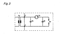
- FIG. 3 A preferred construction of an ignition line 4x to 8x is shown in FIG. 3.
- Transformer 4x To the high voltage output of the High voltage storage capacitor 5x is connected to transformer 4x.
- spark gap 6x In parallel is the series connection of spark gap 6x and spark plug capacity 7x with spark gap 8x.
- the spark plug capacitance is typically approx. 20 pF.
- the capacitance of this spark gap In order for the voltage generated by the transformer 4x to actually drop substantially across the spark gap 6x before the spark gap 6x breaks down, the capacitance of this spark gap must be chosen to be small compared to the spark plug capacitance 7x, so it is preferably of the order of 2 pF.
- the storage capacitor 5x in turn must be so high with its capacitance that after switching through the spark gap, that is if the capacitance of the storage capacitor 5x and the spark plug capacitance 7x are in parallel, the total capacitance is still essentially determined by the capacitance of the storage capacitor 5x.
- the desired value for this voltage is of the order of 30 kV.
- the generation of a voltage of the order of 30 kV at a capacity of the order of a few hundred pF without additional load on the primary energy source, i.e. battery or alternator, is achieved by using the low-loss and low-inductance high-voltage transformers 4x in connection with the absence of an ignition distribution on the High-voltage side and their replacement by the isolators 3x on the low-voltage side of the transformers 4x achieved in the multiplicity of these transformers.
- Particularly suitable values for the high-voltage transformer are of the order of 150 ⁇ H inductance, 350 m ⁇ resistance on the primary side in connection with 350 mH inductance, 180 ⁇ resistance on the secondary side.
- a ferrite core material ensures low core losses.
- the low inductance of the high voltage transformer 4x leads to extremely rapid recharging processes from the medium-voltage storage capacitor into the high-voltage storage capacitor 5x that has just been connected, which, in conjunction with the rapid breakdown of the spark gap which is thereby promoted, provides 6x voltage increases of the order of magnitude 100 kV / us on the spark plug spark gap.
- This favors the energy conversion in the spark gap 8x in the head of the spark, i.e. in the nanosecond range, and contributes to the fact that in the time available about possible shunts, such as could be caused by sooting the insulator body of the spark plug, only negligible energy can drain off.
- the low inductance of the high-voltage transformer 4x makes its combination with the high-voltage storage capacitor 5x or the medium-voltage storage capacitor 1 very rapidly oscillating resonant circuits, so that the energy which is not converted in the nanosecond range can be returned to the medium-voltage storage capacitor.
- a diode can be provided antiparallel to the switching path of the thyristor 3x, which is already blocking at this time.
- the requirements for the isolating element 3x located between the medium-voltage energy store 1 and the high-voltage converter 4x consist primarily in the fact that it can be controlled in a defined time, switches very quickly and is very low-resistance in the switched-through state in order to avoid losses here as well. These requirements are met to a particularly high degree by a fast thyristor, as is available today.
- the separation elements 3x can be actuated in any suitable manner.
- a map computer that can be controlled via signal transmitters 10 (sensors), so that the ignition timing can be adjusted in accordance with engine requirements, load conditions, etc., can be used as the signal converter 9 that controls the isolating elements 3x.
- the signal converter 9 can also be a converted mechanical high-voltage ignition distributor without a high-voltage function, which contains the sensors for negative pressure adjustment, centrifugal force adjustment, cylinder detection, etc.
- a blocking oscillator is preferred as medium-voltage converter 2 because it can be built with relatively little loss, can be optimally adapted in terms of performance, is short-circuit proof and offers a sufficiently rapid voltage rise in the millisecond range. In addition, it can be built small.
- the blocking oscillator principle it is also possible to full charge starting from a primary voltage of 3 V (extreme cold start) the medium-voltage energy storage device 1 having sufficient for 'engine start pulse repetition of about 10 Hz.
- a plurality of medium-voltage energy storage devices 1 act on each ignition branch, with the provision of corresponding additional isolating elements 3x. This means that several high-energy sparks can be processed one after the other per ignition process and spark plug. Since the ignition system sunk follow the battery or alternator draws proportional to the F energy are up to half the maximum spark sequence dual spark triple spark possible for a third of the maximum firing sequence without major load on the battery or dynamo than the maximum spark sequence.
- Temporally consecutive multiple sparks can be realized also in such a way that the energy available to the medium-voltage energy storage device 1 in relaxation oscillations, each voltage sener with the energy content of the high g ie Albanys 5x is converted.
- FIG. 2 shows part of the circuit of Figure 1 in greater detail.
- the signal converter 9 for example a map computer, outputs its output control signals to the light-emitting diodes 20a, 20b, 20c, 20d, ... from optocouplers with which the power section is galvanically isolated from the control elements to suppress crosstalk from one ignition circuit to the other.
- the phototransistors 21a, 21b, 21c, 21d, ... of the optocouplers give their signals to the control electrodes of the thyristors 3a, 3b, 3c, 3d, ..., which are in series with the primary windings of the high-voltage converters 4a, 4b, 4c, 4d , ... lie.
- the voltage of the medium-voltage capacitor 1 charged via the blocking oscillator 2 from the alternator or battery is at a voltage of the order of magnitude 1.
- the Thyristor controlled by signal converter 9, switched through, current flows - because of the low inductance and low resistance of the high-voltage converter 4x and the speed of the thyristor 3x with a short rise time and high peak currents.
- the high-voltage converter transforms the voltage on the primary side high and the high-voltage storage capacitor 5x, which is no longer shown in FIG. 2, is charged with high efficiency in the nanosecond range to the desired voltage of the order of magnitude of 30 kV.
- the decoupling diodes 22x are omitted and diodes connected antiparallel to the thyristors are provided.
- the response voltage of the spark gaps was then increased to 27 kV and the capacitance of the storage capacitors increased to 330 pF.
- the application of the ignition system described is not limited to single and multi-cylinder reciprocating piston engines, but can also be used with rotary piston engines, gas turbines etc. with a wide variety of fuels diesel, gasoline, alcohol, ethanol, hydrogen, hydrogen gasoline, biogas, natural gas, propane etc. with more or less good mixture preparation, more or less emaciated.
Landscapes
- Engineering & Computer Science (AREA)
- Chemical & Material Sciences (AREA)
- Combustion & Propulsion (AREA)
- Mechanical Engineering (AREA)
- General Engineering & Computer Science (AREA)
- Physics & Mathematics (AREA)
- Plasma & Fusion (AREA)
- Ignition Installations For Internal Combustion Engines (AREA)
- Magnetic Heads (AREA)
- Generation Of Surge Voltage And Current (AREA)
Abstract
Description
- Die Erfindung bezieht sich auf eine Zündanlage gemäß Oberbegriff des Patentanspruchs 1.
- Bei der Konzipierung einer Zündanlage ist es Grundziel, Funken mit möglichst hoher Zündfähigkeit zu erreichen. Der Gesichtspunkt hoher Zündfähigkeit gewinnt vor allem an Bedeutung im Zusammenhang mit den heute zur Kraftstoffeinsparung in Entwicklung befindlichen Magerbetriebsmotoren, die zündunwillige und recht träge reagierende Kraftstoff-Luftgemische (Lambda)1,4) verwenden, und mit dem Einsatz von Abgaskatalysatoren, die Zündaussetzer nur in beschränktem Umfang vertragen, weil in den Katalysator gelangender unverbrannter Kraftstoff zu einem Verbrennen des Katalysators führen kann.
- Bei Verwendung eines Hochspannungsspeicherkondensators und einer Vorfunkenstrecke in Verbindung mit der eigentlichen Zündkerzenfunkenstrecke (DE-QS 28 10 159) hat sich eine Möglichkeit zu energiereichen Zündfunken geöffnet, die darüber hinaus den wesentlichen Teil ihrer Energie, was günstig ist; im sogenannten Funkenkopf, also in der Durchbruchsphase, umsetzen. Allerdings muß bei einer solchen Anordnung in Form des Speicherkondensators ein Kondensator hoher Kapazität auf im wesentlichen die Zündspannung aufgeladen werden, was mit herkömmlichen Transistorzündsystemen aufgrund ihres schlechten Wirkungsgrades oder auch bei Hochspannungskondensatorzündsystemen mit an sich gutem Wirkungsgrad aber geringer Leistung bei vertretbarer Bela- stung der primären Energiequelle (Batterie, Lichtmaschine) praktisch nicht möglich ist. Dies liegt vor allem an Verlusten in der Zündspule und im Hochspannungszündverteiler, durch den die Sekundärseite der Zündspule auf den jeweiligen Zündstrang geschaltet wird.
- Vor diesem Hintergrund ist es Aufgabe der Erfindung, eine Zündanlage zu schaffen, welche ohne Verstärkung bzw. zusätzliche Belastung der primären Energiequelle in.der Lage ist, zuverlässig die geforderte Zündspannung bei gleichzeitig energiereichem Zündfunken zu liefern.
- Diese Aufgabe wird erfindungsgemäß gelöst durch eine Zündanlage, wie sie in Anspruch 1 gekennzeichnet ist.
- Die Verwendung des induktivitätsarmen Hochspannungswandlers in der Vielfachheit der Zündstränge und der damit verbundene Verzicht auf einen hochspannungsseitigen Zündverteiler trägt entscheidend dazu bei, daß die Energie verlustarm und äußerst rasch aus dem Mittelspannungsspeicherkondensator, auf den die primäre Energiequelle über den Mittelspannungswandler arbeitet, in den Hochspannungs-Speicherkondensator umgeladen wird. Die Kapazität des Hochspannungs-Speicherkondensators kann dabei ohne Verlust an Aufladesicherheit so hoch gewählt werden, daß auch nach dem Durchschlagen der Vorfunkenstrecke, wenn also Speicherkapazität und Zündkerzenkapazität parallel liegen, die Spannung an der Zündkerzenfunkenstrecke noch so hoch ist, daß sie für alle Betriebszustände an der Zündkerzenfunkenstrecke ausreicht.. Typisch sind bei einer Zündkerzeneigenkapazität von ca. 20 pF Werte der Größenordnung 300 pF für den Hochspannungsspeicherkondensator.
- Die Vorfunkenstrecke stellt einen Schalter dar, der mit Erreichen der Durchbruchsspannung schlagartig ins Niederohmige übergeht, wobei Induktivitätsarmut und Niederohmigkeit des gesamten Zündstranges einschließlich des die hohe Spannung erzeugenden Spannungswandlers dafür sorgen, daß sich Spannungsanstiege and der Zündfunkenstrecke von der Größenordnung 100 kV/µs erreichen lassen. Dadurch geht der größte Teil der in der Zündkerzenfunkenstrecke umgesetzten Energie in den Plasmaaufbau und damit in das zu zündende Gemisch.
- Die für die einzelnen Zündstränge geforderte Niederohmigkeit und Induktivitätsarmut schließt die Schaltelemente, welche den Mittelspannungsspeicherkondensator auf die einzelnen Zündstränge schalten, mit ein. Vorzugsweise werden hierfür Thyristoren eingesetzt, die sich leicht zeitrichtig aufsteuern lassen und von selbst rasch wieder sperren. Für den Mittelspannungswandler, auf den die primäre Niedergleichspannungsquelle arbeitet ist vorzugsweise ein Sperrschwinger vorgesehen. Er ist kurzschlußfest, relativ verlustfrei baubar, läßt sich optimal in der Leistung anpassen und hat einen ausreichend schnellen Spannungsanstieg. Der Mittelspannungsspeicherkondensator,auf den der Spannungswandler arbeitet wird vorzugsweise auf eine Spannung der Größenordnung von 700 V aufgeladen und hat eine Kapazität der Größenordnung von 1,5 µF. Damit läßt sich der hochspannungsseitige Speicherkondensator bei einer Kapazität der Größenordnung von 300 pF auf Spannungswerte von etwa 30 kV aufladen. Eine derart verlustfreie Übertragung hat sich mit herkömmlichen Zündspulen hoher Induktivität und mit einer Zündverteilung auf der Hochspannungsseite als unmöglich erwiesen.
- Im folgenden wird die Erfindung anhand der Zeichnung im einzelnen beschrieben. Auf dieser zeigt
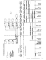
- Fig. 1 ein Blockschaltbild einer Zündanlage eines mehrzylindrigen Verbrennungsmotors,
- Fig. 2 das Schaltbild wesentlicher Teile der Fig. 1 im einzelnen, und
- Fig. 3 das Schaltbild auf der Sekundärseite des Hochspannungswandlers.
- Gemäß Fig. 1 wird ausgehend von einer Spannungsquelle in Form einer Lichtmaschine 12 oder einer Batterie 11 über ein Trennglied in Form eines Schalters ein Spannungswandler 2 in Form eines Sperrschwingers mit einer für diese Spannungsquellen typischen Spannung, also zum Beispiel 12 V oder weniger, beaufschlagt. Der Sperrschwinger 2 lädt einen Mittelspannungsenergiespeicher 1 in Form etwa eines Folienkondensators etwa einer Kapazität von 1,5 9F auf eine Spannung etwa von 700 V auf. Hinter diesem Mittelspannungsen- ergiespeicher 1 verzweigt sich die Schaltung in parallele untereinander gleich aufgebaute Zweige entsprechend der Vielfachheit der zu zündenden Einheiten, d.h. Zündkerzen bzw. Zylinder. Am Ausgang des Mittelspannungsenergiespeichers 1 liegen ansteuerbare Trennglieder, vorzugsweise schnelle Thyristoren, 3a, 3b, 3c, 3d, ... in der Vielfachheit der vorgesehenen Zündstränge parallel. Ein jeder solcher Zündstrang besteht aus einem Hochspannungswandler 4x (x = a, b, c, ...) in Form eines möglichst induktivitätsarmen und ohmsch, dielektrisch und magnetisch besonders verlustarmen Transformators mit hohem Kopplungsfaktor, einem Hochspannunqsenergiespeicher 5x in Form etwa eines Keramikkondensators etwa einer Kapazität der Größenordnung zwischen 200 und 400 pF, einem Trennglied 6x in Form einer druckgasgefüllten Funkenstrecke und einem Energiespeicher 7x mit Energiewandler 8x in Form der Zündkerzeneigenkapazität bzw. der Zündkerzenfunkenstrecke.
- Ein bevorzugter Aufbau eines Zündstranges 4x bis 8x ist in Fig. 3 dargestellt. An den Hochspannungsausgang des Transformators 4x ist der Hochspannungsspeicherkondensator 5x angeschlossen. Ihm parallel liegt die Reihenschaltung aus Vorfunkenstrecke 6x und Zündkerzenkapazität 7x mit Zündfunkenstrecke 8x. Die Zündkerzenkapazität beträgt typischerweise ca. 20 pF. Damit vor dem Durchschlagen der Vorfunkenstrecke 6x die vom Transformator 4x erzeugt Spannung im wesentlichen wirklich an der Vorfunkenstrecke 6x abfällt, muß die Kapazität dieser Vorfunkenstrecke klein gegen die Zündkerzenkapazität 7x gewählt werden, sie ist vorzugsweise also von der Größenordnung 2 pF. Der Speicherkondensator 5x wiederum muß mit seiner Kapazität so hoch liegen, daß nach dem Durchschalten der Vorfunkenstrecke, wenn also die Kapazität des Speicherkondensators 5x und die Zündkerzenkapazität 7x parallel liegen, die Gesamtkapazität weiterhin im wesentlichen durch die Kapazität des Speicherkondensators 5x bestimmt wird. Daraus resultieren Kapazitätswerte für den Speicherkondensator der Größenordnung 100 pF, d.h. 200 bis 400 pF. Dadurch läßt sich erreichen, daß die Spannung an der Zündkerzenfunkenstrecke 8x nach dem Durchschalten der Vorfunkenstrecke 6x nicht wesentlich unter die Spannung absinkt, auf die der Speicherkondensator 5x aufgeladen worden ist. Der angestrebte Wert für diese Spannung ist von der Größenordnung 30 kV.
- Die Erzeugung einer Spannung der Größenordnung von 30 kV an einer Kapazität von der Größenordnung einiger hundert pF ohne zusätzliche Belastung der primären Energiequelle also Batterie bzw. Lichtmaschine, wird durch die Verwendung derverlust-und induktivitätsarmen Hochspannungstransformatoren 4x in Verbindung mit dem Verzicht auf eine Zündverteilung auf der Hochspannungsseite und deren Ersatz durch die Trennglieder 3x auf der Niederspannungsseite der Transformatoren 4x in der Vielfachheit dieser Transformatoren erreicht.
- Besonders geeignete Werte für den Hochspannungstransformator sind von der Größenordnung 150 µH Induktivität, 350 mΩ Widerstand primärseitig in Verbindung mit 350 mH Induktivität, 180 Ω Widerstand sekundärseitig. Für geringe Kernverluste sorgt ein Ferritkernmaterial.
- Die Induktivitätsarmut des Hochspannungstransformators 4x führt zu äußerst raschen Umladevorgängen aus dem Mittelspannungsspeicherkondensator in den gerade aufgeschalteten Hochspannungsspeicherkondensator 5x, was in Verbindung mit dem dadurch begünstigten raschen Durchschlagen der Vorfunkenstrecke 6x Spannungsanstiege von der Größenordnung 100 kV/us an der Zündkerzenfunkenstrecke liefert. Dies begünstigt den Energieumsatz in der Zündfunkenstrecke 8x im Kopf des Zündfunkens, also im Nanosekundenbereich, und trägt dazu bei, daß in der zur Verfügung stehenden Zeit über eventuelle Nebenschlüsse, wie sie beispielsweise durch Verrußungen des Isolatorkörpers der Zündkerze gegeben sein könnten, nur vernachläßigbar wenig Energie abfließen kann.
- Die Induktivitätsarmut des Hochspannungstransformators 4x macht seine Kombination mit dem Hochspannungsspeicherkondensator 5x bzw. dem Mittelspannungspeicherkondensator 1 zu sehr schnell schwingenden Schwingkreisen, so daß die nicht im Nanosekundenbereich umgesetzte Energie in den Mittelspannungsspeicherkondensator zurückgeführt werden kann. Um dies zu ermöglichen, kann antiparallel zur Schaltstrecke des zu diesem Zeitpunkt schon sperrenden Thyristors 3x eine Diode vorgesehen sein.
- Die Anforderungen an das zwischen Mittelspannungsenergiespeicher 1 und Hochspannungswandler 4x liegende Trennglied 3x bestehen vor allem darin, daß es zeitlich definiert ansteuerbar ist, sehr schnell schaltet und im durchgeschalteten Zustand sehr niederohmig ist, um auch hier Verluste zu vermeiden. Diese Anforderungen werden durch einen schnellen Thyristor, wie er heute verfügbar ist, in besonders hohem Maße erfüllt.
- Die Ansteuerung der Trennglieder 3x kann auf beliebige geeignete Weise erfolgen. Als die Trennglieder 3x ansteuernder Signalwandler 9 kommt beispielsweise ein Kennfeldrechner in Frage, der über Signalgeber 10 (Sensoren) angesteuert wird, so daß der Zündzeitpunkt entsprechend den Motorerfordernissen, Lastzuständen usw. verstellt werden kann. Der Signalwandler 9 kann auch ein umgebauter mechanischer Hochspannungszündverteiler ohne Hochspannungsfunktion sein, der die Sensoren für Unterdruckverstellung, Fliehkraftverstellung, Zylindererkennung usw. beinhaltet.
- Als Mittelspannungswandler 2 wird ein Sperrschwinger bevorzugt, da er relativ verlustarm gebaut werden kann, sich optimal in der Leistung anpassen läßt, kurzschlußfest ist und einen ausreichend schnellen Spannungsanstieg im Millisekundenbereich bietet. Darüber hinaus läßt er sich klein bauen. Durch Anwendung des Sperrschwingerprinzips ist es überdies möglich, bereits ab einer Primärspannung von 3 V (extremer Kaltstart) den Mittelspannungsenergiespeicher 1 mit einer für 'Motorstarts ausreichenden Impulsfolge von etwa 10 Hz voll aufzuladen.
- In Weiterbildung des beschriebenen Prinzips kann vorgesehen sein, daß jeweils mehrere Mittelspannungsenergiespeicher 1 unter Vorsehung entsprechender zusätzlicher Trennglieder 3x auf jeden Zündstrang einwirken. Damit lassen sich pro Zündvorgang und Zündkerze jeweils mehrere energiereiche Funken nacheinander abwickeln. Da die Zündanlage proportional der Funkenfolge der Batterie bzw. Lichtmaschine Energie entnimmt, sind bis zur halben maximalen Funkenfolge Zweifachfunken, bei einem Drittel der maximalen Zündfolge Dreifachfunken ohne größere Belastung der Batterie oder Lichmaschine als bei der maximalen Funkenfolge möglich.
- Zeitlich aufeinanderfolgende Mehrfachfunken lassen sich auch in der Weise realisieren, daß die zur Verfügung stehende Energie des Mittelspannungsenergiespeichers 1 in Kippschwingungen, jeweils mit dem Energieinhalt des Hoch- spannungsenergiespeichers 5x umgewandelt wird.
- Um die Niederohmigkeit der Zündanlage zu gewährleisten, ist es zweckmäßig die Anlage kompakt und mit kurzen Leitungswegen auszubilden. Fig. 1 zeigt mehrere mögliche Schnittstellen in der Gesamtkette mit der sich dadurch ergebenden möglichen Zusammenfassung von Teilkomponenten in bestimmten Baueinheiten.
- Fig. 2 zeigt einen Teil der Schaltung von Fig. 1 in größeren Einzelheiten. Der Signalwandler 9, etwa ein Kennfeldrechner gibt seine Ausgangssteuersignale auf die Leuchtdioden 20a, 20b, 20c, 20d, ... von Optokopplern aus, mit denen zur Unterdrückung eines Ubersprechens von einem Zündstrang auf den anderen'der Leistungsteil von den Steuerelementen galvanisch getrennt ist. Die Phototransistoren 21a, 21b, 21c, 21d, ... der Optokoppler geben ihre Signale auf die Steuerelektroden der Thyristoren 3a, 3b, 3c, 3d, ..., die in Reihe mit den Primärwicklungen der Hochspannungswandler 4a, 4b, 4c, 4d, ... liegen. An der Reihenschaltung aus Primärwicklung des Hochspannungstransformators 4x und dem Thyristor 3x, in der auch noch eine Entkopplungsdiode 22x vorhanden ist, liegt die Spannung des über den Sperrschwinger 2 aus der Lichtmaschine oder Batterie auf eine Spannung der Größenordnung einige 100 V aufgeladenen Mittelspannungskondensators 1. Sobald der Thyristor,vom Signalwandler 9 angesteuert, durchschaltet, fließt Strom - wegen der Induktivitätsarmut und Niederohmigkeit des Hochspannungswandlers 4x und der Schnelligkeit des Thyristors 3x mit kurzer Anstiegszeit und hohen Spitzenstromstärken. Der Hochspannungswandler transformiert die primärseitige Spannung dabei hoch und der in Fig. 2 nicht mehr gezeigte Hochspannungsspeicherkondensator 5x wird mit hohem Wirkungsgrad im Nanosekundenberich auf die gewünschte Spannung der Größenordnung von 30 kV aufgeladen.
- Ist eine Rückspeisung der nicht im Nanosekundenbereich umgesetzten Energie in den Mittelspannungsspeicherkondensator gewünscht, so entfallen die Entkopplungs-Dioden 22x und es sind antiparallel zu den Thyristoren verschaltete Dioden vorgesehen.
- Zur Belegung der Wirksamkeit der beschriebenen Zündanlage wurde folgender Versuch unternommen:
- Ein Sechszylindermotor wurde zunächst mit einer herkömmlichen Transistorzündung mit mechanischem Hochspannungsverteiler, ergänzt um Vorfunkenstecker mit 100 pF und Vorfunkenstrecken von 20 kV,betrieben. Dabei ergaben sich folgende Mängel:
- a) Das Gemisch im Motor ist nur bedingt abmagerungsfähig, die ans Gas abgegebene Energie von 20 mJ ist nicht ausreichend für alle Betriebszustände. Die primärseitige Leistungsaufnahme betrug 96 W.
- b) Da beim Kaltstart bis 23 kV an der Zündkerze auftreten, wird zwar durch die Vorfunkenstrecke bis 20 kV abgesperrt, darüber steigt die Spannung an der Zündkerze aber mit normaler Geschwindigkeit von ca. 400 V/gs an. Bei leitfähigem Belag fließt oft zuviel Energie über den Isolatorfuß der Zündkerze ab, so daß es zu Zündaussetzern kommt.
- c) Zumindest bei kaltem, innen betautem mechanischen Verteiler kommt.:es hier zuHochspannungsüberschlägen bereits bei ca. 17 kV und damit zu Zündaussetzern.
- Die Ansprechspannung der Funkenstrecken wurde dann auf 27 kV erhöht und die Kapazitäten der Speicherkondensatoren auf 330 pF angehoben.
- Mit keiner handelsüblichen, bekannten Zündung konnte diese Kombination zum Durchschalten gebracht werden. Die Beibehaltung des Konstruktionsprinzips hätte zu einer Leistungsaufnahme an der Batterie bzw. Lichtmaschine von 360 W geführt, was ohne Verstärkung von Batterie bzw. Lichtmaschine nicht möglich gewesen wäre. Die Zündspule als Energiezwischenspeicher wurde nun durch einen über einen Sperrschwinger auf 700 V aufzuladenden Kondensator einer Kapazität von 1,5 µF ersetzt und dieser über in der Vielfachheit der Zündkerzen niederspannungsseitig vorhandene Thyristoren und verlust- sowie induktivitätsarme Transformatoren in die 330 pF-Hochspannungsspeicherkondensatoren umgeladen.
- Damit war es dann möglich, die Kombination aus 330 pF Speicherkondensator und 27 kV Vorfunkenstrecke durchzuschalten und für jeden Motorbetriebspunkt die mindestens 23 kV an der Zündkerze als Nadelimpuls mit einer Anstiegszeit von 100 kV/µs anzubieten.
- Die Anwendung der beschriebenen Zündanlage beschränkt sich nicht auf Ein- und Mehrzylinderhubkolbenmotore, sondern kann auch bei Rotationskolbenmotoren, Gasturbinen usw. mit den verschiedensten Kraftstoffen Diesel, Benzin,Alkohol, Äthanol, Wasserstoff, Wasserstoff-Benzin, Biogas, Erdgas, Propan usw. bei mehr oder weniger guter Gemischaufbereitung, mehr oder weniger abgemagert, verwendet werden.
- Die günstige Energieausnützung bei der beschriebenen Zündung ermöglicht es, sie bei reduzierter Zündenergie etwa auch für Zusatzheizungen für Kraftfahrzeuge zu verwenden. Als primäre Energiequellen sind wegen des hohen Wirkungsgrads der Zündanlage auch Solarzellen oder handbetriebene Dynamos vorstellbar, ebenso für Kurzzeitbetrieb leistungsfähige Batterien, die einen Stoßstrom von z.B. 2 A bringen.
Claims (6)
Priority Applications (1)
| Application Number | Priority Date | Filing Date | Title |
|---|---|---|---|
| AT86104406T ATE70598T1 (de) | 1985-04-15 | 1986-04-01 | Zuendanlage. |
Applications Claiming Priority (2)
| Application Number | Priority Date | Filing Date | Title |
|---|---|---|---|
| DE3513422 | 1985-04-15 | ||
| DE3513422A DE3513422C2 (de) | 1985-04-15 | 1985-04-15 | Zündanlage für Brennkraftmaschinen |
Publications (2)
| Publication Number | Publication Date |
|---|---|
| EP0200010A1 true EP0200010A1 (de) | 1986-11-05 |
| EP0200010B1 EP0200010B1 (de) | 1991-12-18 |
Family
ID=6268042
Family Applications (1)
| Application Number | Title | Priority Date | Filing Date |
|---|---|---|---|
| EP86104406A Expired - Lifetime EP0200010B1 (de) | 1985-04-15 | 1986-04-01 | Zündanlage |
Country Status (9)
| Country | Link |
|---|---|
| US (1) | US4727891A (de) |
| EP (1) | EP0200010B1 (de) |
| JP (1) | JPS61241465A (de) |
| AT (1) | ATE70598T1 (de) |
| BR (1) | BR8601692A (de) |
| DD (1) | DD245702A5 (de) |
| DE (1) | DE3513422C2 (de) |
| ES (1) | ES8706903A1 (de) |
| IN (1) | IN166150B (de) |
Cited By (2)
| Publication number | Priority date | Publication date | Assignee | Title |
|---|---|---|---|---|
| EP0242839A3 (en) * | 1986-04-24 | 1988-03-30 | Elena Spa | Electronically-controlled plasma ignition device for internal combustion engines |
| WO1992021875A1 (de) * | 1991-05-31 | 1992-12-10 | Robert Bosch Gmbh | Zündanlagen für brennkraftmaschinen mit hochspannungsschalter |
Families Citing this family (12)
| Publication number | Priority date | Publication date | Assignee | Title |
|---|---|---|---|---|
| DE3731393A1 (de) * | 1987-09-18 | 1989-04-06 | Bosch Gmbh Robert | Hochspannungsschalter |
| JPH04349386A (ja) * | 1991-05-27 | 1992-12-03 | West Electric Co Ltd | 内燃機関点火装置用の定電圧放電管 |
| US6559376B2 (en) | 1996-09-30 | 2003-05-06 | Nology Engineering, Inc. | Combustion initiation device and method for tuning a combustion initiation device |
| AU5621400A (en) * | 1999-09-15 | 2001-04-17 | Knite, Inc. | Electronic circuits for plasma-generating devices |
| DE10048053A1 (de) * | 2000-09-28 | 2002-06-06 | Christoph Koerber | Plasmastrahl-Zündsystem |
| US6374816B1 (en) | 2001-04-23 | 2002-04-23 | Omnitek Engineering Corporation | Apparatus and method for combustion initiation |
| US6679235B1 (en) * | 2003-02-21 | 2004-01-20 | Delphi Technologies, Inc. | High power ignition system having high impedance to protect the transformer |
| GB0720939D0 (en) * | 2007-10-24 | 2007-12-05 | Powell Jude A | Coolign device |
| AT507748A1 (de) * | 2008-12-16 | 2010-07-15 | Ge Jenbacher Gmbh & Co Ohg | Zündeinrichtung |
| EP2663767A2 (de) | 2011-01-13 | 2013-11-20 | Federal-Mogul Ignition Company | Koronarzündungssystem mit selektiver lichtbogenbildung |
| FR3032232B1 (fr) * | 2015-01-30 | 2017-03-10 | Meggitt (France) | Generateur d'allumage a haute energie notamment pour turbine a gaz |
| DE102015002104B4 (de) | 2015-02-23 | 2024-08-01 | Spectro Analytical Instruments Gmbh | Energieeffizienter und immanent sicherer Anregungsgenerator |
Citations (5)
| Publication number | Priority date | Publication date | Assignee | Title |
|---|---|---|---|---|
| US3361932A (en) * | 1963-05-01 | 1968-01-02 | Rotax Ltd | A.c. operated spark ignition apparatus with compensation for changes in the frequency of the a.c. source |
| GB2099917A (en) * | 1981-04-07 | 1982-12-15 | Nissan Motor | Plasma ignition systems for internal combustion engines |
| EP0066749A1 (de) * | 1981-06-01 | 1982-12-15 | Aisin Seiki Kabushiki Kaisha | Zündsystem für Brennkraftmaschinen mit innerer Verbrennung |
| DE3236092A1 (de) * | 1981-10-05 | 1983-04-21 | Nissan Motor Co., Ltd., Yokohama, Kanagawa | Plasma-zuendsystem fuer eine brennkraftmaschine |
| WO1985003980A1 (en) * | 1984-02-27 | 1985-09-12 | Pate Ronald C | Combustion initiation system employing hard discharge ignition |
Family Cites Families (16)
| Publication number | Priority date | Publication date | Assignee | Title |
|---|---|---|---|---|
| US2950419A (en) * | 1956-12-07 | 1960-08-23 | Bendix Corp | Ignition apparatus |
| US3331034A (en) * | 1964-09-10 | 1967-07-11 | Gen Motors Corp | Converter stabilizing circuit |
| DE1439995C3 (de) * | 1964-11-27 | 1974-02-07 | Beru-Werk Albert Ruprecht, 7140 Ludwigsburg | Funkentstörtes Kondensatorzündgerät |
| US3575153A (en) * | 1968-11-18 | 1971-04-20 | Eltra Corp | Regulated voltage converter |
| US3629651A (en) * | 1969-09-25 | 1971-12-21 | Bendix Corp | Pulse-generating apparatus |
| GB1371042A (en) * | 1970-10-20 | 1974-10-23 | Plessey Co Ltd | Spark generating systems for internal combustion engines |
| GB1473325A (en) * | 1973-06-29 | 1977-05-11 | Lucas Industries Ltd | Spark ignition systems for internal combustion engines |
| US4027198A (en) * | 1975-08-14 | 1977-05-31 | The Bendix Corporation | Capacitor discharge ignition system |
| GB1571884A (en) * | 1975-12-03 | 1980-07-23 | Lucas Industries Ltd | Spark ignition systems for gas turbine engines |
| DE2810159C3 (de) * | 1978-03-09 | 1984-11-08 | Bloss, Werner H., Prof. Dr.-Ing., 7065 Winterbach | Einrichtung zur Zündung brennfähiger Gemische |
| JPS57203867A (en) * | 1981-06-09 | 1982-12-14 | Nissan Motor Co Ltd | Plasma ignition apparatus |
| US4391236A (en) * | 1981-07-24 | 1983-07-05 | Outboard Marine Corporation | CD Ignition with automatic spark retard |
| SE437286B (sv) * | 1982-07-09 | 1985-02-18 | Saab Scania Ab | Tendsystem for flercylindrig fyrtaktmotor |
| US4479467A (en) * | 1982-12-20 | 1984-10-30 | Outboard Marine Corporation | Multiple spark CD ignition system |
| US4487192A (en) * | 1983-04-18 | 1984-12-11 | Ford Motor Co | Plasma jet ignition system |
| US4562823A (en) * | 1983-07-15 | 1986-01-07 | Nippon Soken, Inc. | Ignition device for internal combustion engine |
-
1985
- 1985-04-15 DE DE3513422A patent/DE3513422C2/de not_active Expired - Fee Related
-
1986
- 1986-04-01 AT AT86104406T patent/ATE70598T1/de not_active IP Right Cessation
- 1986-04-01 EP EP86104406A patent/EP0200010B1/de not_active Expired - Lifetime
- 1986-04-02 IN IN304/DEL/86A patent/IN166150B/en unknown
- 1986-04-11 DD DD86289028A patent/DD245702A5/de unknown
- 1986-04-15 BR BR8601692A patent/BR8601692A/pt not_active IP Right Cessation
- 1986-04-15 JP JP61085192A patent/JPS61241465A/ja active Pending
- 1986-04-15 ES ES553995A patent/ES8706903A1/es not_active Expired
- 1986-04-15 US US06/852,285 patent/US4727891A/en not_active Expired - Fee Related
Patent Citations (5)
| Publication number | Priority date | Publication date | Assignee | Title |
|---|---|---|---|---|
| US3361932A (en) * | 1963-05-01 | 1968-01-02 | Rotax Ltd | A.c. operated spark ignition apparatus with compensation for changes in the frequency of the a.c. source |
| GB2099917A (en) * | 1981-04-07 | 1982-12-15 | Nissan Motor | Plasma ignition systems for internal combustion engines |
| EP0066749A1 (de) * | 1981-06-01 | 1982-12-15 | Aisin Seiki Kabushiki Kaisha | Zündsystem für Brennkraftmaschinen mit innerer Verbrennung |
| DE3236092A1 (de) * | 1981-10-05 | 1983-04-21 | Nissan Motor Co., Ltd., Yokohama, Kanagawa | Plasma-zuendsystem fuer eine brennkraftmaschine |
| WO1985003980A1 (en) * | 1984-02-27 | 1985-09-12 | Pate Ronald C | Combustion initiation system employing hard discharge ignition |
Cited By (3)
| Publication number | Priority date | Publication date | Assignee | Title |
|---|---|---|---|---|
| EP0242839A3 (en) * | 1986-04-24 | 1988-03-30 | Elena Spa | Electronically-controlled plasma ignition device for internal combustion engines |
| WO1992021875A1 (de) * | 1991-05-31 | 1992-12-10 | Robert Bosch Gmbh | Zündanlagen für brennkraftmaschinen mit hochspannungsschalter |
| US5379745A (en) * | 1991-05-31 | 1995-01-10 | Robert Bosch Gmbh | Ignition system for internal combustion engines with high-tension switches |
Also Published As
| Publication number | Publication date |
|---|---|
| US4727891A (en) | 1988-03-01 |
| JPS61241465A (ja) | 1986-10-27 |
| ATE70598T1 (de) | 1992-01-15 |
| EP0200010B1 (de) | 1991-12-18 |
| ES8706903A1 (es) | 1987-07-01 |
| DE3513422A1 (de) | 1986-12-18 |
| BR8601692A (pt) | 1986-12-16 |
| ES553995A0 (es) | 1987-07-01 |
| DD245702A5 (de) | 1987-05-13 |
| IN166150B (de) | 1990-03-17 |
| DE3513422C2 (de) | 1993-10-28 |
Similar Documents
| Publication | Publication Date | Title |
|---|---|---|
| DE3586682T2 (de) | Pulsiertes plasmazuendungsystem. | |
| EP0200010B1 (de) | Zündanlage | |
| DE3221885C2 (de) | Plasma-Zündsystem für eine mehrere Zylinder aufweisende Brennkraftmaschine | |
| DE69029649T2 (de) | Plasma-Zündanlage | |
| DE3221990C2 (de) | Plasmazündanlage für eine mehrzylindrige Brennkraftmaschine | |
| DE3137239C2 (de) | Plasmazündvorrichtung für eine Brennkraftmaschine | |
| DE2340865A1 (de) | Zuendvorrichtung fuer brennkraftmaschinen | |
| DE2702021C2 (de) | Zündanlage für einen mehrzylindrigen Verbrennungsmotor | |
| WO2012130649A1 (de) | Verfahren und vorrichtung zur verlängerung der brenndauer eines von einer zündkerze gezündeten funkens in einem verbrennungsmotor | |
| DE69123395T2 (de) | Gleichstrom-Zündungssystem | |
| EP0228840A2 (de) | Impuls-Erzeuger-Schaltung für Zündsysteme | |
| DE19625422A1 (de) | Hybridzündschaltung für einen Verbrennungsmotor | |
| DE102011089966A1 (de) | Verfahren zum Betreiben einer Zündvorrichtung für eine Verbrennungskraftmaschine | |
| EP1620946B1 (de) | Trigger-/zündeinrichtung in einem aus n stufenkondensatoren bestehenden marx-generator | |
| DE2814779A1 (de) | Zuendsystem | |
| DE1414588B2 (de) | Zuendeinrichtung fuer brennkraftmaschinen | |
| DE2363804A1 (de) | Kondensatorzuendkerze | |
| EP0484357A1 (de) | Vollelektronische zündeinrichtung für eine brennkraftmaschine | |
| DE3302198A1 (de) | Zuendsystem fuer einen motor mit innerer verbrennung | |
| DE60012073T2 (de) | Zündsystem für eine fahrzeugantreibende Brennkraftmaschine | |
| DE2531278C3 (de) | Zündeinrichtung für Brennkraftmaschinen | |
| DE3404245A1 (de) | Hochspannungs-generatorschaltung fuer ein kraftfahrzeugzuendsystem | |
| DE2237837A1 (de) | Zuendeinrichtung fuer einen verbrennungskraftmotor | |
| DE3505988A1 (de) | Fuer eine brennkraftmaschine bestimmte zuendeinrichtung | |
| DE2531302B2 (de) | Zuendeinrichtung fuer brennkraftmaschinen |
Legal Events
| Date | Code | Title | Description |
|---|---|---|---|
| PUAI | Public reference made under article 153(3) epc to a published international application that has entered the european phase |
Free format text: ORIGINAL CODE: 0009012 |
|
| AK | Designated contracting states |
Kind code of ref document: A1 Designated state(s): AT BE FR GB IT NL SE |
|
| 17P | Request for examination filed |
Effective date: 19870410 |
|
| 17Q | First examination report despatched |
Effective date: 19890126 |
|
| GRAA | (expected) grant |
Free format text: ORIGINAL CODE: 0009210 |
|
| AK | Designated contracting states |
Kind code of ref document: B1 Designated state(s): AT BE FR GB IT NL SE |
|
| REF | Corresponds to: |
Ref document number: 70598 Country of ref document: AT Date of ref document: 19920115 Kind code of ref document: T |
|
| GBT | Gb: translation of ep patent filed (gb section 77(6)(a)/1977) | ||
| ET | Fr: translation filed | ||
| ITF | It: translation for a ep patent filed | ||
| PGFP | Annual fee paid to national office [announced via postgrant information from national office to epo] |
Ref country code: GB Payment date: 19920327 Year of fee payment: 7 |
|
| PGFP | Annual fee paid to national office [announced via postgrant information from national office to epo] |
Ref country code: SE Payment date: 19920429 Year of fee payment: 7 Ref country code: AT Payment date: 19920429 Year of fee payment: 7 |
|
| PGFP | Annual fee paid to national office [announced via postgrant information from national office to epo] |
Ref country code: FR Payment date: 19920430 Year of fee payment: 7 Ref country code: BE Payment date: 19920430 Year of fee payment: 7 |
|
| PLBE | No opposition filed within time limit |
Free format text: ORIGINAL CODE: 0009261 |
|
| STAA | Information on the status of an ep patent application or granted ep patent |
Free format text: STATUS: NO OPPOSITION FILED WITHIN TIME LIMIT |
|
| 26N | No opposition filed | ||
| PG25 | Lapsed in a contracting state [announced via postgrant information from national office to epo] |
Ref country code: GB Effective date: 19930401 Ref country code: AT Effective date: 19930401 |
|
| PG25 | Lapsed in a contracting state [announced via postgrant information from national office to epo] |
Ref country code: SE Effective date: 19930402 |
|
| PG25 | Lapsed in a contracting state [announced via postgrant information from national office to epo] |
Ref country code: BE Effective date: 19930430 |
|
| PGFP | Annual fee paid to national office [announced via postgrant information from national office to epo] |
Ref country code: NL Payment date: 19930430 Year of fee payment: 8 |
|
| BERE | Be: lapsed |
Owner name: BERU RUPRECHT G.M.B.H. & CO. K.G. Effective date: 19930430 |
|
| GBPC | Gb: european patent ceased through non-payment of renewal fee |
Effective date: 19930401 |
|
| PG25 | Lapsed in a contracting state [announced via postgrant information from national office to epo] |
Ref country code: FR Effective date: 19931229 |
|
| REG | Reference to a national code |
Ref country code: FR Ref legal event code: ST |
|
| PG25 | Lapsed in a contracting state [announced via postgrant information from national office to epo] |
Ref country code: NL Effective date: 19941101 |
|
| NLV4 | Nl: lapsed or anulled due to non-payment of the annual fee | ||
| EUG | Se: european patent has lapsed |
Ref document number: 86104406.3 Effective date: 19931110 |
|
| PG25 | Lapsed in a contracting state [announced via postgrant information from national office to epo] |
Ref country code: IT Free format text: LAPSE BECAUSE OF NON-PAYMENT OF DUE FEES;WARNING: LAPSES OF ITALIAN PATENTS WITH EFFECTIVE DATE BEFORE 2007 MAY HAVE OCCURRED AT ANY TIME BEFORE 2007. THE CORRECT EFFECTIVE DATE MAY BE DIFFERENT FROM THE ONE RECORDED. Effective date: 20050401 |