EP0200034A2 - Dispositif pour fabriquer des récipients en plastique - Google Patents
Dispositif pour fabriquer des récipients en plastique Download PDFInfo
- Publication number
- EP0200034A2 EP0200034A2 EP86104758A EP86104758A EP0200034A2 EP 0200034 A2 EP0200034 A2 EP 0200034A2 EP 86104758 A EP86104758 A EP 86104758A EP 86104758 A EP86104758 A EP 86104758A EP 0200034 A2 EP0200034 A2 EP 0200034A2
- Authority
- EP
- European Patent Office
- Prior art keywords
- mold
- mold halves
- starting position
- extrusion press
- halves
- Prior art date
- Legal status (The legal status is an assumption and is not a legal conclusion. Google has not performed a legal analysis and makes no representation as to the accuracy of the status listed.)
- Granted
Links
Images
Classifications
-
- B—PERFORMING OPERATIONS; TRANSPORTING
- B29—WORKING OF PLASTICS; WORKING OF SUBSTANCES IN A PLASTIC STATE IN GENERAL
- B29C—SHAPING OR JOINING OF PLASTICS; SHAPING OF MATERIAL IN A PLASTIC STATE, NOT OTHERWISE PROVIDED FOR; AFTER-TREATMENT OF THE SHAPED PRODUCTS, e.g. REPAIRING
- B29C49/00—Blow-moulding, i.e. blowing a preform or parison to a desired shape within a mould; Apparatus therefor
- B29C49/28—Blow-moulding apparatus
- B29C49/30—Blow-moulding apparatus having movable moulds or mould parts
- B29C49/32—Blow-moulding apparatus having movable moulds or mould parts moving "to and fro"
-
- B—PERFORMING OPERATIONS; TRANSPORTING
- B29—WORKING OF PLASTICS; WORKING OF SUBSTANCES IN A PLASTIC STATE IN GENERAL
- B29C—SHAPING OR JOINING OF PLASTICS; SHAPING OF MATERIAL IN A PLASTIC STATE, NOT OTHERWISE PROVIDED FOR; AFTER-TREATMENT OF THE SHAPED PRODUCTS, e.g. REPAIRING
- B29C49/00—Blow-moulding, i.e. blowing a preform or parison to a desired shape within a mould; Apparatus therefor
- B29C49/02—Combined blow-moulding and manufacture of the preform or the parison
- B29C49/06905—Using combined techniques for making the preform
- B29C49/0691—Using combined techniques for making the preform using sheet like material, e.g. sheet blow-moulding from joined sheets
-
- B—PERFORMING OPERATIONS; TRANSPORTING
- B29—WORKING OF PLASTICS; WORKING OF SUBSTANCES IN A PLASTIC STATE IN GENERAL
- B29C—SHAPING OR JOINING OF PLASTICS; SHAPING OF MATERIAL IN A PLASTIC STATE, NOT OTHERWISE PROVIDED FOR; AFTER-TREATMENT OF THE SHAPED PRODUCTS, e.g. REPAIRING
- B29C51/00—Shaping by thermoforming, i.e. shaping sheets or sheet like preforms after heating, e.g. shaping sheets in matched moulds or by deep-drawing; Apparatus therefor
- B29C51/18—Thermoforming apparatus
- B29C51/20—Thermoforming apparatus having movable moulds or mould parts
-
- B—PERFORMING OPERATIONS; TRANSPORTING
- B29—WORKING OF PLASTICS; WORKING OF SUBSTANCES IN A PLASTIC STATE IN GENERAL
- B29C—SHAPING OR JOINING OF PLASTICS; SHAPING OF MATERIAL IN A PLASTIC STATE, NOT OTHERWISE PROVIDED FOR; AFTER-TREATMENT OF THE SHAPED PRODUCTS, e.g. REPAIRING
- B29C2791/00—Shaping characteristics in general
- B29C2791/004—Shaping under special conditions
- B29C2791/006—Using vacuum
Definitions
- the present invention relates to a device for producing plastic containers according to the preamble of claim 1.
- the object on which the present invention is based is best for carin to provide a device of the generic type for a continuous production process for plastic waste containers, in which the mold halves are returned to the starting position with a significantly higher return speed compared to the speed at which the film strips are ejected, in order to largely reduce the downtime due to the process , and at which the speed difference between the ejection and return speed is compensated energetically by means of a defined force.
- These power means are preferably formed by coil springs or by gas pressure springs.
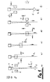
- an extruder 1 which ejects molten plastic material via a double muno piece in the form of two separate film strips 3, 4.
- the two openings of the double piece are arranged at a distance from one another, so that the film strips are pressed out at a distance from one another.
- the film banks 3, 4 are then removed at a suitable distance from the extrusion press 1 along their longitudinal edges by means of a pulling mechanism (not shown).
- the finished plastic containers 5 are then separated from the plague foil strips here.
- the extrusion press 1 is the extrusion press 1 with the two film strips 3, 4 ejected in parallel, as well as the fact that these film strips 3, 4 are ejected continuously from the extrusion press 1 and from a pull-off mechanism deducted continuously, together.
- the discharge direction is marked with X, the material speed with V 1 .
- the actual functional element of the device for carrying out the method is a mold consisting of two mold halves 6, 7, in which the plastic container 5 is formed.
- the mold halves 6, 7 each have a dashed cavity, to which vacuum is applied from the outside, so that the part of the film strip 3 or 4 that comes to lie just in front of the cavity of the corresponding mold half 6, 7 into the cavity is drawn in and is deformed to a half of the age.
- the still plastic material of the foil clips 3, 4 is then welded to one another along an edge around the cavities.
- the mold consisting of the mold halves 6, 7 also migrates away from the extrusion press 1 together with the clamped film strips 3, 4 at an ejection speed V.
- the mold After the aforementioned cooling time has expired, the mold has reached its position in which the container 5 is finished and can be removed. In this position, the mold halves 6, 7 are moved apart (arrow d) ... Fig. 1 d.
- Fig. 1 e is already indicated by the file Y that the mold halves 6, 7 are now moved back to their starting position. It has been shown, as will be explained with reference to the device according to FIG. 2, that the mold halves can be moved from the end position to the starting position back to K considerably faster than it corresponds to the ejection speed V 1 ; these Return speed is marked with V 2 .
- Fig. 1 f again shows the starting position. The mold halves 6, 7 are opened again; they are closed with the next working cycle in order to form a next container 5.
- the extrusion press 1 can continuously eject the film strips 3, 4 without the risk that film material builds up over the mold halves and without the film strips 3, 4 with the containers 5 must be deducted via an intermittently operated extraction mechanism.
- the mold moves continuously with the film strips 3, 4 away from the extrusion press 1 and only opens when the container 5 has cooled (and is therefore rigid). From this open position, the mold is then treated with a respect to the discharge speed V 1 is preferably substantially larger returning speed V 2 returned to the initial position.
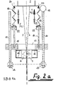
- the device for carrying out the method is explained with reference to FIG. 2. Attention is drawn in particular to the force means which are integrated into the device for accelerated return of the mold halves to their starting position.
- FIG. 2 a shows the device in the working position, in which the shape consisting of the two mold halves 6, 7 has the necessary distance from the extrusion press 1, which is predetermined in relation to the thermoplastic material.
- the mold halves 6, 7 are still closed; the container 5 is welded in this position and cooled so that it can be removed.
- the mold halves 6, 7 have been shared with the clamped foil bands 3, 4 with the ejected G eschwindig- velocity v 1 of the extruder 1 is moved away (arrow X).
- This availability is mediated via threaded spindles 1 0, 11, over a Motot 12 and two gear units 13, 14 are positively coupled.
- the threaded spindles 1 0 , 11 are in turn positively and non-positively connected to a holding plate 15 which can be raised and lowered relative to the extrusion press 1 via the threaded spindles 1 0 , 11.
- the holding plate 15 in turn carries the mold halves 6, 7 which can be displaced relative to one another on the holding plate 15 in a plane perpendicular to the direction of movement (X, Y) (cf. b, d in FIGS. 1 and 2 b).
- This displacement option is also realized via threaded spindles 16, which are coupled in terms of force and are driven by an electric motor (not shown).
- the holding plate 15 has a through opening, through which the film strips 3, 4 are pulled and are pulled off via the pull-off mechanism mentioned at the beginning.
- the shape is arranged on the side of the holding plate 15 facing away from the extruder 1.
- the inventive design of this device described so far consists in that the holding plate 15 are suspended via a type of spring accumulator, generally via force means, which are charged to a certain extent when the mold is occupied in the direction X, i. H. is enriched with Enerdie.
- force means which are charged to a certain extent when the mold is occupied in the direction X, i. H. is enriched with Enerdie.
- the balanced dimensioning of the springs relative to the weight of the moving holding plate 15 ensures that the springs are relieved relatively when the F latte is occupied beyond the zero point, thereby creating a force component (in the X direction) downwards. In this way, the same result is achieved in the upper reversal point as in the lower reversal point; the additional energy required for acceleration is required by the storage unit and not by the drive motor.
- the spring accumulator mentioned is formed in the example of FIG. 2 by tension springs 18 which are connected on the one hand via tie rods 19 to the holding plate 15 and on the other hand to a fixed point located in the area of the extruder 1.
- spring accumulator can be implemented as a hydropneumatic or pneumatic accumulator or as a pressure spring accumulator.
- connection between the tie rod 10 and the tension spring 18 has a stop 21, can be limited via the beg of the holding plate 15 and thus the mold halves 6, 7.
- a guide ring 22 is provided which is fixed relative to the extrusion press 1. If the stop 21 - as shown in FIG. 2a - has reached the guide ring 22, the end position of the holding plate 15 or the shape has been reached; the tension springs 18 are maximally elongated and thus have a maximum of spring energy stored.
- the mold In the working position shown in FIG. 2a, the mold is now opened in terms of time; the container is released and pulled off the pull-off mechanism. Overlapping in time, the return of the holding plate 15 with the mold halves 6, 7 is initiated.
- This recirculation is energetically supported by the data stored in the tension springs 18 energy, in particular in so far particularly positive influence on the G e-complete system has erheblicn than the return speed V 2, in particular ten times, may be greater than the discharge speed V1.
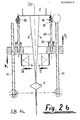
- F ig. 2b shows the mold halves 6, 7 in the starting position closest to the extruder 1.
- the mold halves 6, 7 are opened in accordance with file d.
- the holding plate 15 has been moved into this starting position via the threaded spindle 10, 11, using the energy stored in the tension springs 18 with the relatively high return speed V 2. Mechanically, this starting position is defined in that the holding plate 15 rests on the guide ring 22 .
- the tension springs 16 are relaxed in this starting position; the last manufactured container 5 is pulled down.
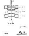
- the time relation between the travel time from item 5 to item 1 and the travel time between F os. 1 and Fos. 5 depending on the design of the drive unit about 5 ... 1 0 ; that is, the mold is moved back to its upper closing position at a high return speed V 2 relative to the ejection speed V 1 , which ultimately enables a very favorable cycle time to be achieved.
- the shape or the use of the spring energy requires only relatively little additional energy to be supplied from the outside.
- the motor is practically only for the path between the Fos. o and Fos. 1 required, d. H. turn on.
- the motor is only required as an additional drive on the way from the central position to item 5, in which the mold halves 6, 7 are opened again. Approximately half of the total cycle time thus runs without additional motor power, so that the present invention also provides a considerable advantage in terms of energy, namely energy saving.
Landscapes
- Engineering & Computer Science (AREA)
- Mechanical Engineering (AREA)
- Manufacturing & Machinery (AREA)
- Blow-Moulding Or Thermoforming Of Plastics Or The Like (AREA)
- Extrusion Moulding Of Plastics Or The Like (AREA)
- Processing And Handling Of Plastics And Other Materials For Molding In General (AREA)
Priority Applications (1)
| Application Number | Priority Date | Filing Date | Title |
|---|---|---|---|
| AT86104758T ATE48968T1 (de) | 1985-04-15 | 1986-04-08 | Vorrichtung zur herstellung von kunststoffbeh|ltern. |
Applications Claiming Priority (2)
| Application Number | Priority Date | Filing Date | Title |
|---|---|---|---|
| DE19853513399 DE3513399A1 (de) | 1985-04-15 | 1985-04-15 | Verfahren und vorrichtung zur herstellung von kunststoff-behaeltern |
| DE3513399 | 1985-04-15 |
Publications (3)
| Publication Number | Publication Date |
|---|---|
| EP0200034A2 true EP0200034A2 (fr) | 1986-11-05 |
| EP0200034A3 EP0200034A3 (en) | 1987-01-21 |
| EP0200034B1 EP0200034B1 (fr) | 1989-12-27 |
Family
ID=6268025
Family Applications (1)
| Application Number | Title | Priority Date | Filing Date |
|---|---|---|---|
| EP86104758A Expired EP0200034B1 (fr) | 1985-04-15 | 1986-04-08 | Dispositif pour fabriquer des récipients en plastique |
Country Status (5)
| Country | Link |
|---|---|
| US (1) | US4720367A (fr) |
| EP (1) | EP0200034B1 (fr) |
| JP (1) | JPS61274926A (fr) |
| AT (1) | ATE48968T1 (fr) |
| DE (1) | DE3513399A1 (fr) |
Families Citing this family (3)
| Publication number | Priority date | Publication date | Assignee | Title |
|---|---|---|---|---|
| JP2931715B2 (ja) * | 1992-05-12 | 1999-08-09 | 三菱電機株式会社 | 樹脂封止方法、樹脂封止装置、及びガススプリング |
| AUPN843596A0 (en) * | 1996-03-04 | 1996-03-28 | Pacific Dunlop Limited | Cable componentry |
| CA2699318C (fr) * | 2007-10-01 | 2016-06-28 | Inventio Ag | Dispositif d'emboutissage |
Family Cites Families (16)
| Publication number | Priority date | Publication date | Assignee | Title |
|---|---|---|---|---|
| GB747434A (en) * | 1953-11-02 | 1956-04-04 | Alfonso Amigo | Improvements in or relating to the production of hollow bodies from organic plastic materials |
| US3235638A (en) * | 1961-09-07 | 1966-02-15 | Hedwin Corp | Method for forming plastic containers |
| FR71716E (fr) * | 1957-06-06 | 1960-01-19 | Procédé de fabrication de corps creux en matière thermoplastique | |
| US3003187A (en) * | 1958-10-16 | 1961-10-10 | Owens Illinois Glass Co | Method and apparatus for forming and trimming hollow plastic articles |
| US3238565A (en) * | 1961-09-22 | 1966-03-08 | Sun Chemical Corp | Continuous hot forming apparatus |
| US3256565A (en) * | 1962-12-31 | 1966-06-21 | Formex Mfg Inc | Vacuum forming apparatus |
| US3196513A (en) * | 1963-02-11 | 1965-07-27 | Parma Domenico | Machine for making precast concrete products |
| US3454693A (en) * | 1963-10-23 | 1969-07-08 | Helene M Crenshaw | Process for forming plastic objects |
| GB1194821A (en) * | 1966-04-22 | 1970-06-10 | Calmec Extruform Ltd | Improvements in or relating to the Moulding of Articles from Thermoplastics Material |
| GB1138435A (en) * | 1967-02-22 | 1969-01-01 | Rolls Royce | Improvements relating to moulding |
| US3552545A (en) * | 1969-02-27 | 1971-01-05 | Byron King Hartman | Vibratory hopper and trough coupled as a two-mass tuned vibratory system |
| US3699199A (en) * | 1970-12-30 | 1972-10-17 | Hercules Inc | Continuous blow molding process with reduction of length compensation |
| DE2150903A1 (de) * | 1971-10-13 | 1973-04-19 | Dserschinskij Sawod Plastitsch | Anlage zum herstellen von ampullen mit rueckschlagventil |
| NO130629C (fr) * | 1972-12-11 | 1975-01-15 | Dyno Industrier As | |
| US4025250A (en) * | 1975-11-25 | 1977-05-24 | Macmillan Mold Co., Inc. | Segmented matrix with guide means and retaining pins |
| DE3027045A1 (de) * | 1980-07-17 | 1982-02-11 | Hegler, Wilhelm, 8730 Bad Kissingen | Flach-hohlkoerper, insbesondere lueftungs- und drainage- bzw. absorber-platte |
-
1985
- 1985-04-15 DE DE19853513399 patent/DE3513399A1/de active Granted
-
1986
- 1986-04-08 AT AT86104758T patent/ATE48968T1/de not_active IP Right Cessation
- 1986-04-08 EP EP86104758A patent/EP0200034B1/fr not_active Expired
- 1986-04-15 US US06/852,284 patent/US4720367A/en not_active Expired - Lifetime
- 1986-04-15 JP JP61085214A patent/JPS61274926A/ja active Granted
Also Published As
| Publication number | Publication date |
|---|---|
| ATE48968T1 (de) | 1990-01-15 |
| JPS61274926A (ja) | 1986-12-05 |
| EP0200034B1 (fr) | 1989-12-27 |
| US4720367A (en) | 1988-01-19 |
| JPH0579017B2 (fr) | 1993-11-01 |
| DE3513399C2 (fr) | 1988-03-03 |
| EP0200034A3 (en) | 1987-01-21 |
| DE3513399A1 (de) | 1986-10-16 |
Similar Documents
| Publication | Publication Date | Title |
|---|---|---|
| DE69217870T2 (de) | Verfahren und Vorrichtung zum Giessen von Kunststoffverbundmaterial | |
| DE3620175C2 (fr) | ||
| EP0361187A1 (fr) | Procédé et dispositif de fabrication de corps creux en matière thermoplastique | |
| DE3513388A1 (de) | Vorrichtung zur herstellung von kunststoff-formteilen insbesondere von kunststoff-hohlkoerpern | |
| DE1479336A1 (de) | Vorrichtung zum Herstellen von Behaeltern | |
| EP0612605B1 (fr) | Machine de moulage par soufflage | |
| DE1299406B (de) | Verfahren und Vorrichtung zum Herstellen von Flaschen u. dgl. Hohl-koerpern aus warmformbaren Kunststoffen | |
| DE2906858A1 (de) | Pressgussvorrichtung | |
| EP0074473B1 (fr) | Procédé et dispositif pour la fabrication de pièces de forme ou des objets en matière plastique | |
| DE1479571A1 (de) | Behaelter aus thermoplastischem Kunststoff,Verfahren zur Herstellung desselben und Vorrichtung zur Durchfuehrung des Verfahrens | |
| EP0402645B1 (fr) | Dispositif pour surmouler une pièce en matière thermoplastique | |
| DE1038750B (de) | Verfahren und Vorrichtung zur Herstellung von Flaschen oder aehnlichen Hohlkoerpern aus organischen thermoplastischen Kunststoffen | |
| EP0200034B1 (fr) | Dispositif pour fabriquer des récipients en plastique | |
| DE2544171C3 (de) | Vorrichtung zum Steuern der Bewegung der Blasform und der Teile derselben beim Herstellen von Hohlkörpern aus thermoplastischem Kunststoff | |
| DE2155114A1 (de) | Vorrichtung zum Antrieb von Wagen längs einer geschlossenen Bahn | |
| EP0595203B1 (fr) | Dispositif de moulage par injection | |
| DE1137854B (de) | Maschine zur kontinuierlichen Herstellung von Hohlkoerpern aus einem thermo-plastischen Kunststoffschlauch | |
| DE2427246A1 (de) | Vorrichtung zur herstellung eines aus einem rohteil und einem angeformten spritzgussteil zusammengesetzten gegenstandes | |
| DE3929664A1 (de) | Verfahren und vorrichtung zur herstellung von behaeltern mit einem anschlusselement, wie zum beispiel einem fuell- und/oder entnahmestutzen | |
| AT265625B (de) | Vorrichtung zur Herstellung eines Hohlkörpers aus einem stranggepreßten Schlauch aus Kunststoff | |
| DE2855200C2 (de) | Spritzvorrichtung zum Herstellen von Gegenständen aus thermoplastischem Kunststoff | |
| DE1479714C3 (de) | Rotierend kontinuierlich arbeitende Anlage zum Vakuumformen von Hohlkörpern aus Kunststoff | |
| DE1813367C3 (de) | Vorrichtung zum Herstellen von Hohl korpern, insbesondere Flaschen, Dosen od dgl aus thermoplastischem Kunststoff im B las verfahren | |
| DE2556350B2 (de) | Verfahren zum Transportieren einer thermoplastisch verformbaren Kunststoff-Folie zwischen einem Extruder und einer Thermoformmaschine und Maschine zur Durchführung des Verfahrens | |
| DE1479176C (de) | Vorrichtung zum Aussondern des von den Fertigteilen abgetrennten Abfalls, der beim Herstellen von Hohlkörpern aus warmformbarem Kunststoff im Blas verfahren entsteht |
Legal Events
| Date | Code | Title | Description |
|---|---|---|---|
| PUAI | Public reference made under article 153(3) epc to a published international application that has entered the european phase |
Free format text: ORIGINAL CODE: 0009012 |
|
| AK | Designated contracting states |
Kind code of ref document: A2 Designated state(s): AT CH FR GB IT LI |
|
| PUAL | Search report despatched |
Free format text: ORIGINAL CODE: 0009013 |
|
| AK | Designated contracting states |
Kind code of ref document: A3 Designated state(s): AT CH FR GB IT LI |
|
| 17P | Request for examination filed |
Effective date: 19870713 |
|
| 17Q | First examination report despatched |
Effective date: 19880415 |
|
| GRAA | (expected) grant |
Free format text: ORIGINAL CODE: 0009210 |
|
| AK | Designated contracting states |
Kind code of ref document: B1 Designated state(s): AT CH FR GB IT LI |
|
| REF | Corresponds to: |
Ref document number: 48968 Country of ref document: AT Date of ref document: 19900115 Kind code of ref document: T |
|
| ITF | It: translation for a ep patent filed | ||
| GBT | Gb: translation of ep patent filed (gb section 77(6)(a)/1977) | ||
| ET | Fr: translation filed | ||
| PLBE | No opposition filed within time limit |
Free format text: ORIGINAL CODE: 0009261 |
|
| STAA | Information on the status of an ep patent application or granted ep patent |
Free format text: STATUS: NO OPPOSITION FILED WITHIN TIME LIMIT |
|
| 26N | No opposition filed | ||
| ITTA | It: last paid annual fee | ||
| PGFP | Annual fee paid to national office [announced via postgrant information from national office to epo] |
Ref country code: FR Payment date: 20000324 Year of fee payment: 15 |
|
| PGFP | Annual fee paid to national office [announced via postgrant information from national office to epo] |
Ref country code: GB Payment date: 20000405 Year of fee payment: 15 |
|
| PGFP | Annual fee paid to national office [announced via postgrant information from national office to epo] |
Ref country code: AT Payment date: 20000428 Year of fee payment: 15 |
|
| PGFP | Annual fee paid to national office [announced via postgrant information from national office to epo] |
Ref country code: CH Payment date: 20000712 Year of fee payment: 15 |
|
| PG25 | Lapsed in a contracting state [announced via postgrant information from national office to epo] |
Ref country code: GB Free format text: LAPSE BECAUSE OF NON-PAYMENT OF DUE FEES Effective date: 20010408 Ref country code: AT Free format text: LAPSE BECAUSE OF NON-PAYMENT OF DUE FEES Effective date: 20010408 |
|
| PG25 | Lapsed in a contracting state [announced via postgrant information from national office to epo] |
Ref country code: FR Free format text: THE PATENT HAS BEEN ANNULLED BY A DECISION OF A NATIONAL AUTHORITY Effective date: 20010430 |
|
| PG25 | Lapsed in a contracting state [announced via postgrant information from national office to epo] |
Ref country code: LI Free format text: LAPSE BECAUSE OF NON-PAYMENT OF DUE FEES Effective date: 20010507 Ref country code: CH Free format text: LAPSE BECAUSE OF NON-PAYMENT OF DUE FEES Effective date: 20010507 |
|
| GBPC | Gb: european patent ceased through non-payment of renewal fee |
Effective date: 20010408 |
|
| REG | Reference to a national code |
Ref country code: CH Ref legal event code: PL |
|
| REG | Reference to a national code |
Ref country code: FR Ref legal event code: ST |
|
| PG25 | Lapsed in a contracting state [announced via postgrant information from national office to epo] |
Ref country code: IT Free format text: LAPSE BECAUSE OF NON-PAYMENT OF DUE FEES;WARNING: LAPSES OF ITALIAN PATENTS WITH EFFECTIVE DATE BEFORE 2007 MAY HAVE OCCURRED AT ANY TIME BEFORE 2007. THE CORRECT EFFECTIVE DATE MAY BE DIFFERENT FROM THE ONE RECORDED. Effective date: 20050408 |