EP0200151A2 - Process for obtaining solid cyanuric chloride - Google Patents
Process for obtaining solid cyanuric chloride Download PDFInfo
- Publication number
- EP0200151A2 EP0200151A2 EP86105613A EP86105613A EP0200151A2 EP 0200151 A2 EP0200151 A2 EP 0200151A2 EP 86105613 A EP86105613 A EP 86105613A EP 86105613 A EP86105613 A EP 86105613A EP 0200151 A2 EP0200151 A2 EP 0200151A2
- Authority
- EP
- European Patent Office
- Prior art keywords
- cyanuric chloride
- inert gas
- separator
- chloride
- vapor
- Prior art date
- Legal status (The legal status is an assumption and is not a legal conclusion. Google has not performed a legal analysis and makes no representation as to the accuracy of the status listed.)
- Granted
Links
- MGNCLNQXLYJVJD-UHFFFAOYSA-N cyanuric chloride Chemical compound ClC1=NC(Cl)=NC(Cl)=N1 MGNCLNQXLYJVJD-UHFFFAOYSA-N 0.000 title claims abstract description 52
- 238000000034 method Methods 0.000 title claims abstract description 22
- 239000007787 solid Substances 0.000 title claims abstract description 9
- 239000011261 inert gas Substances 0.000 claims abstract description 39
- QPJDMGCKMHUXFD-UHFFFAOYSA-N cyanogen chloride Chemical compound ClC#N QPJDMGCKMHUXFD-UHFFFAOYSA-N 0.000 claims abstract description 9
- 238000005829 trimerization reaction Methods 0.000 claims abstract description 8
- 238000004519 manufacturing process Methods 0.000 claims description 2
- 239000003380 propellant Substances 0.000 claims description 2
- 238000011084 recovery Methods 0.000 abstract description 5
- 238000009833 condensation Methods 0.000 abstract description 3
- 230000005494 condensation Effects 0.000 abstract description 3
- 238000000926 separation method Methods 0.000 description 7
- 239000007789 gas Substances 0.000 description 5
- 239000002245 particle Substances 0.000 description 5
- 230000008021 deposition Effects 0.000 description 4
- ZAMOUSCENKQFHK-UHFFFAOYSA-N Chlorine atom Chemical compound [Cl] ZAMOUSCENKQFHK-UHFFFAOYSA-N 0.000 description 3
- YMWUJEATGCHHMB-UHFFFAOYSA-N Dichloromethane Chemical compound ClCCl YMWUJEATGCHHMB-UHFFFAOYSA-N 0.000 description 3
- 239000000460 chlorine Substances 0.000 description 3
- 229910052801 chlorine Inorganic materials 0.000 description 3
- 239000010419 fine particle Substances 0.000 description 3
- IJGRMHOSHXDMSA-UHFFFAOYSA-N Atomic nitrogen Chemical compound N#N IJGRMHOSHXDMSA-UHFFFAOYSA-N 0.000 description 2
- HEDRZPFGACZZDS-UHFFFAOYSA-N Chloroform Chemical compound ClC(Cl)Cl HEDRZPFGACZZDS-UHFFFAOYSA-N 0.000 description 2
- 239000000110 cooling liquid Substances 0.000 description 2
- 239000013078 crystal Substances 0.000 description 2
- 239000011541 reaction mixture Substances 0.000 description 2
- 238000001228 spectrum Methods 0.000 description 2
- 230000015572 biosynthetic process Effects 0.000 description 1
- 230000003197 catalytic effect Effects 0.000 description 1
- 239000000356 contaminant Substances 0.000 description 1
- 238000001816 cooling Methods 0.000 description 1
- 238000002425 crystallisation Methods 0.000 description 1
- 230000008025 crystallization Effects 0.000 description 1
- 238000009826 distribution Methods 0.000 description 1
- 239000003814 drug Substances 0.000 description 1
- 239000000975 dye Substances 0.000 description 1
- 230000000694 effects Effects 0.000 description 1
- 238000001704 evaporation Methods 0.000 description 1
- 238000002474 experimental method Methods 0.000 description 1
- 230000002349 favourable effect Effects 0.000 description 1
- 230000005484 gravity Effects 0.000 description 1
- 239000012535 impurity Substances 0.000 description 1
- 239000000203 mixture Substances 0.000 description 1
- 229910052757 nitrogen Inorganic materials 0.000 description 1
- 239000011814 protection agent Substances 0.000 description 1
- 230000000171 quenching effect Effects 0.000 description 1
- 239000012495 reaction gas Substances 0.000 description 1
- 230000000630 rising effect Effects 0.000 description 1
- 239000005060 rubber Substances 0.000 description 1
- 238000010079 rubber tapping Methods 0.000 description 1
- 238000007711 solidification Methods 0.000 description 1
- 230000008023 solidification Effects 0.000 description 1
- 239000007921 spray Substances 0.000 description 1
- 239000004753 textile Substances 0.000 description 1
Images

Classifications
-
- C—CHEMISTRY; METALLURGY
- C07—ORGANIC CHEMISTRY
- C07D—HETEROCYCLIC COMPOUNDS
- C07D251/00—Heterocyclic compounds containing 1,3,5-triazine rings
- C07D251/02—Heterocyclic compounds containing 1,3,5-triazine rings not condensed with other rings
- C07D251/12—Heterocyclic compounds containing 1,3,5-triazine rings not condensed with other rings having three double bonds between ring members or between ring members and non-ring members
- C07D251/26—Heterocyclic compounds containing 1,3,5-triazine rings not condensed with other rings having three double bonds between ring members or between ring members and non-ring members with only hetero atoms directly attached to ring carbon atoms
- C07D251/28—Only halogen atoms, e.g. cyanuric chloride
Definitions
- the present invention relates to a process for the recovery of solid cyanuric chloride from the cyanuric chloride vapor obtained in the trimerization of cyanogen chloride.
- Cyanuric chloride is of considerable importance as a technical intermediate for the production of dyes, crop protection agents, pharmaceuticals and textile and rubber auxiliaries and is obtained after the catalytic trimerization of cyanogen chloride as a gas together with unreacted cyanogen chloride and chlorine.
- This gas mixture is usually passed into separation chambers and the cyanuric chloride is deposited on the cooled walls.
- a disadvantage of this type of desublimation is the fact that the cyanuric chloride in the form of coarse crystals adheres to the walls and discharge devices and thus has a negative effect on the heat transfer. Regular tapping of the caking from the walls only leads to a brief improvement in the heat transfer. Furthermore, due to the increasing damage to the separator and noise pollution, this method is by no means satisfactory, not to mention the poor quality of the product obtained in this way.
- the present invention was therefore based on the object of developing a process for the recovery of solid cyanuric chloride from the cyanuric chloride vapor obtained in the trimerization of cyanogen chloride, which does not have the disadvantages mentioned in the prior art and which enables a fine-grained cyanuric chloride with a narrow Produce grain spectrum with technically simple means.
- This object was achieved according to the invention by a process for the recovery of solid cyanuric chloride from the trimerization of Ch.
- the cyanuric chloride vapor obtained from lorcyan is dissolved, which is characterized in that the cyanuric chloride vapor in the lower part of the separator is introduced into the center of many individual, cold, ring-shaped, inert gas streams and the solid cyanuric chloride accumulating at the bottom of the separator is discharged, while the heated inert gas is drawn off to the side.
- the reaction mixture obtained in the trimerization of cyanogen chloride is introduced into the lower part of a separation chamber in such a way that it is in the center of many individual inert gas streams which move from bottom to top. This prevents the cyanuric chloride vapor from coming into contact with the walls of the separator and from the formation of coarse crystals or agglomerates.
- the inert gas stream can be split into individual partial streams using the customary nozzles which are arranged concentrically around the cyanuric chloride feed line.
- the cyanuric chloride vapor and the inert gas streams are circulated using a propulsion jet.
- the inert gas streams are supplied with the aid of an annular nozzle which consists of a tubular ring with a corresponding number of holes and which is referred to as a jet ring.
- a jet ring Through this jetting ring, the inert gas partial flows flow down at high speed separation chamber. Due to the high speed of the inert gas flows, a negative pressure is created in the center of the jet ring, which causes gas circulation. The rising gas. which entrains the condensed cyanuric chloride particles is deflected at the top of the separator and then sucked down on the walls and cooled there. - At the height of the ring nozzle, the inert gas flows undergo a change of direction again and are directed upwards again.
- the inert gas streams are preferably introduced into the separation chamber at a very high speed, in particular at more than 80 m / s. Inert gas streams are particularly preferably introduced into the separation chamber at the speed of sound. Due to this high speed, the cyanuric chloride and the inert gas are circulated as a propellant jet in the deposition chamber, the cyanuric chloride vapor being rapidly mixed with the inert gas.
- the inert gas streams expediently have a temperature of from -80 ° C. to +100 ° C., preferably from 0 ° C. to +40 ° C. In this temperature range, the quenching effect is sufficient in any case so that the cyanuric chloride particles are obtained in the desired finely divided form .
- the mass flow ratio of cyanuric chloride vapor to inert gas is not critical and can be varied within wide limits.
- the excess, heated inert gas which still contains small amounts of very fine particles and impurities in cyanogen chloride and chlorine, is preferably drawn off laterally in the lower part of the separator. After cooling and removal of the contaminants by known methods, the inert gas can be returned to the separator.
- Figure 1 shows a preferred embodiment of the method according to the invention.
- the cooled inert gas enters the separation chamber 2 through line 1 and is broken down into many partial streams of high speed with the help of the jet ring.
- the cyanuric chloride vapor is fed to the separator via line 3.
- the excess, heated inert gas is drawn off via line 4 and the deposited cyanuric chloride is discharged at the bottom of the separator via line 5.
Landscapes
- Chemical & Material Sciences (AREA)
- Organic Chemistry (AREA)
- Organic Low-Molecular-Weight Compounds And Preparation Thereof (AREA)
- Vaporization, Distillation, Condensation, Sublimation, And Cold Traps (AREA)
Abstract
0 Es wird ein Verfahren zur Gewinnung von festem Cyanurchlorid aus dem bei der Trimerisierung von Chlorcyan anfalllenden Cyanurchloriddampf beschrieben, wobei man den Cyanurchloriddampf im unteren Teil des Abscheiders in das Zentrum vieler einzelner, kalter, ringförmig angeordneter Inertgasströme einleitet und das am Boden des Abscheiders anfallende feste Cyanurchlorid austrägt, während das erwärmte Inertgas seitlich abgezogen wird. Die Vorteile des erfindungsgemäßen Verfahrens sind hohe Kondensationsdurchsätze, geringe Probleme bezüglich von Anbackungen sowie gute Produktqualität des anfallenden Cyanurchlorids.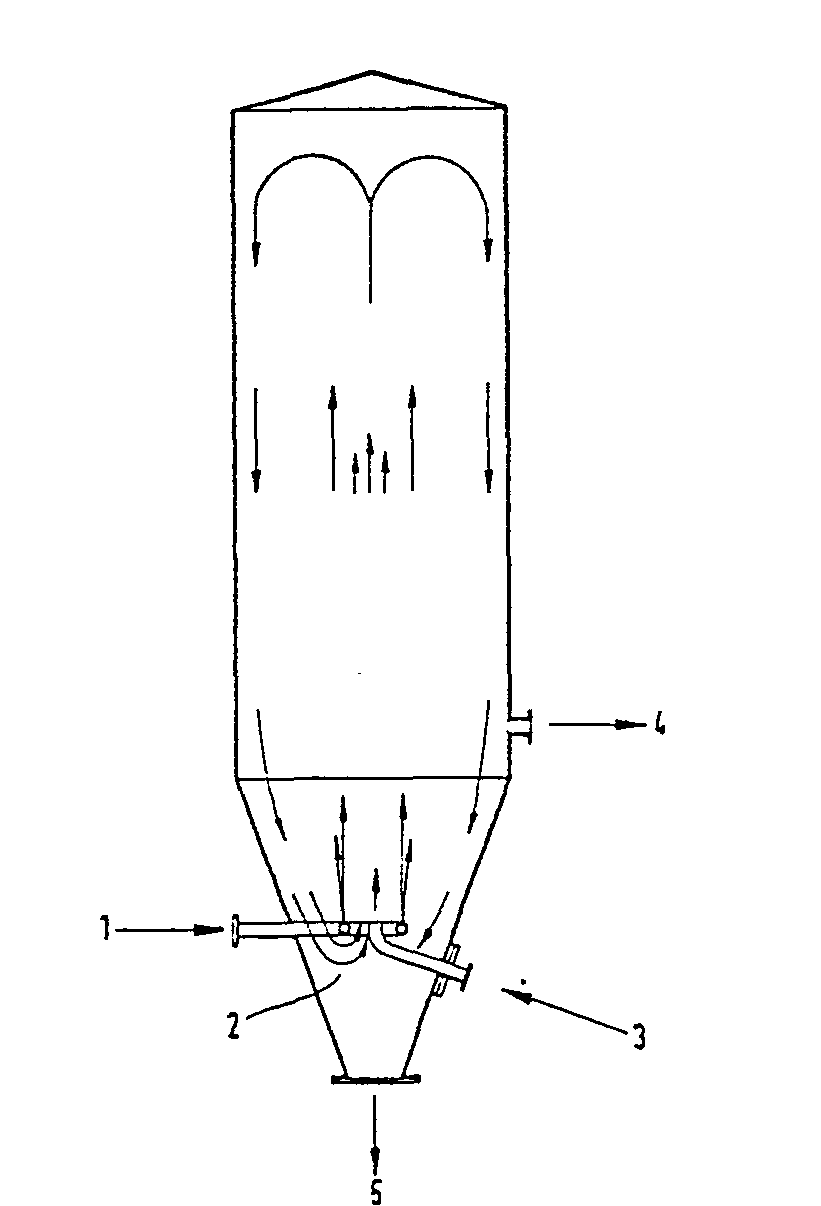
Description
Gegenstand der vorliegenden Erfindung ist ein Verfahren zur Gewinnung von festem Cyanurchlorid aus dem bei der Trimerisierung von Chlorcyan anfallenden Cyanurchloriddampf.The present invention relates to a process for the recovery of solid cyanuric chloride from the cyanuric chloride vapor obtained in the trimerization of cyanogen chloride.
Cyanurchlorid besitzt als technisches Zwischenprodukt für die Herstellung von Farbstoffen, Pflanzenschutzmitteln, Pharmazeutika sowie Textil-und Kautschukhilfsmitteln erhebliche Bedeutung und fällt nach der katalytischen Trimerisierung von Chlorcyan als Gas zusammen mit unumgesetzten Chlorcyan und Chlor an. Dieses Gasgemisch wird üblicherweise in Abscheidekammern geleitet und das Cyanurchlorid an den gekühlten Wänden abgeschieden. Nachteilig bei dieser Art der Desublimation ist der Umstand, daß sich das Cyanurchlorid in Form grober Kristalle an den Wänden und Austragsvorrichtungen festsetzt und somit den Wärmeübergang negativ beeinflußt. Das regelmäßige Abklopfen der Anbackungen von den Wänden führt lediglich zu einer kurzzeitigen Verbesserung des Wärmeübergangs. Darüber hinaus ist diese Methode wegen der zunehmenden Beschädigung des Abscheiders und Lärmbelästigung keineswegs befriedigend, ganz abgesehen von der schlechten Qualität des auf diese Weise erhaltenen Produkts.Cyanuric chloride is of considerable importance as a technical intermediate for the production of dyes, crop protection agents, pharmaceuticals and textile and rubber auxiliaries and is obtained after the catalytic trimerization of cyanogen chloride as a gas together with unreacted cyanogen chloride and chlorine. This gas mixture is usually passed into separation chambers and the cyanuric chloride is deposited on the cooled walls. A disadvantage of this type of desublimation is the fact that the cyanuric chloride in the form of coarse crystals adheres to the walls and discharge devices and thus has a negative effect on the heat transfer. Regular tapping of the caking from the walls only leads to a brief improvement in the heat transfer. Furthermore, due to the increasing damage to the separator and noise pollution, this method is by no means satisfactory, not to mention the poor quality of the product obtained in this way.
Gemäß der DE-AS 12 66 308 hat man versucht, dieses Problem dadurch zu lösen, daß man das Cyanurchlorid zusammen mit einer leicht verdampfenden Kühlflüssigkeit wie z.B. Methylenchlorid oder Chloroform versprühte. Man erhält auf diese Weise zwar ein feinverteiltes Cyanurchlorid, doch ist die Rückgewinnung der Kühlflüssigkeit technisch sehr aufwendig. Darüber hinaus kommt es sehr leicht zu Verstopfungen der Düse.According to DE-AS 12 66 308, attempts have been made to solve this problem by combining the cyanuric chloride with a readily evaporating cooling liquid such as e.g. Sprayed methylene chloride or chloroform. A finely divided cyanuric chloride is obtained in this way, but the recovery of the cooling liquid is technically very complex. In addition, the nozzle becomes clogged very easily.
Anstelle der direkten Abscheidung des Cyanurchloriddampfes wurde z. B. gemäß der DE-PS 25 37 673 und DE-PS 23 32 636 vorgeschlagen, das im Reaktionsgas enthaltene Cyanurchlorid vor der Verfestigung zu verflüssigen und anschließend zu versprühen, wobei die Abführung der Desublimationswärme geringere Probleme aufwirft und Chlor sowie Chlorcyan vor der Abscheidung entfernt werden können. Dieses zweistufige Verfahren ist technisch ziemlich aufwendig. Diesen Nachteil weisen auch die Verfahren gemäß der deutschen Auslegeschriften 28 43 381 und 28 43 382 auf, bei denen man das nach der Trimerisierung von Cyanurchlorid anfallende Reaktionsgemisch in eine Apparatekombination, bestehend aus Abtriebskolonne und Kondensator, einleitet und durch Temperaturregelung am Austritt des Kondensators das Cyanurchlorid in der Kolonne teilweise kondensiert, während der gasförmige Anteil, der am Kolonnenkopf austritt, in den üblichen Abscheidekammem desublimiert wird. Dieses Verfahren verursacht jedoch hohe Betriebs-und Investitionskosten.Instead of the direct deposition of the cyanuric chloride vapor z. B. proposed according to DE-PS 25 37 673 and DE-PS 23 32 636 to liquefy the cyanuric chloride contained in the reaction gas before solidification and then to spray it, the removal of the heat of desublimation raising fewer problems and removing chlorine and cyanogen chloride before the deposition can be. This two-step process is technically quite complex. This disadvantage also has the processes according to German designations 28 43 381 and 28 43 382, in which the reaction mixture obtained after the trimerization of cyanuric chloride is introduced into an apparatus combination consisting of stripping column and condenser, and the temperature of the cyanuric chloride at the outlet of the condenser partially condensed in the column, while the gaseous fraction that emerges at the top of the column is desublimated in the usual separating chambers. However, this method causes high operating and investment costs.
Der vorliegenden Erfindung lag daher die Aufgabe zugrunde, ein Verfahren zur Gewinnung von festem Cyanurchlorid aus dem bei der Trimerisierung von Chlorcyan anfallenden Cyanurchloriddampf zu entwickeln, das die genannten Nachteile des Standes der Technik nicht aufweist, und das es ermöglicht, ein feinkörniges Cyanurchlorid mit einem engen Kornspektrum mit technisch einfachen Mitteln herzustellen.The present invention was therefore based on the object of developing a process for the recovery of solid cyanuric chloride from the cyanuric chloride vapor obtained in the trimerization of cyanogen chloride, which does not have the disadvantages mentioned in the prior art and which enables a fine-grained cyanuric chloride with a narrow Produce grain spectrum with technically simple means.
Diese Aufgabe wurde erfindungsgemäß durch ein Verfahren zur Gewinnung von festem Cyanurchlorid aus dem bei der Trimerisierung von Ch-.' lorcyan anfallenden Cyanurchloriddampf gelöst, das dadurch gekennzeichnet ist, daß man den Cyanurchloriddampf im unteren Teil des Abscheiders in das Zentrum vieler einzelner kalter, ringförmig angeordneter, Inertgasströme einleitet und das am Boden des Abscheiders anfallende feste Cyanurchlorid austrägt, während das erwärmte Inertgas seitlich abgezogen wird.This object was achieved according to the invention by a process for the recovery of solid cyanuric chloride from the trimerization of Ch. The cyanuric chloride vapor obtained from lorcyan is dissolved, which is characterized in that the cyanuric chloride vapor in the lower part of the separator is introduced into the center of many individual, cold, ring-shaped, inert gas streams and the solid cyanuric chloride accumulating at the bottom of the separator is discharged, while the heated inert gas is drawn off to the side.
Es hat sich nämlich überraschenderweise gezeigt, daß sich mit Hilfe des erfindungsgemäßen Verfahrens ein sehr reines Cyanurchlorid, mit einem wesentlich höheren Durchsatz, als es mit bekannten Verfahren möglich ist, gewinnen läßt. Das so erhaltene Cyanurchlorid ist feinteilig und hat eine günstige Verteilung der Korngrößen.Surprisingly, it has been shown that a very pure cyanuric chloride can be obtained with the aid of the process according to the invention, with a significantly higher throughput than is possible with known processes. The cyanuric chloride thus obtained is finely divided and has a favorable distribution of the grain sizes.
Gemäß der vorliegenden Erfindung wird das bei der Trimerisierung von Chlorcyan anfallende Reaktionsgemisch so in den unteren Teil einer Abscheidekammer eingeleitet, daß es sich im Zentrum vieler einzelner Inertgasströme befindet, die sich von unten nach oben bewegen. Auf diese Weise wird verhindert, daß der Cyanurchloriddampf mit den Wänden des Abscheiders in Berührung kommt und daß sich hierbei grobe Kristalle oder Agglomerate bilden. Die Aufspaltung des Inertgasstromes in einzelne Teilströme kann mit den üblichen Düsen erfolgen, die konzentrisch um die Cyanurchloridzuleitung angeordnet sind.According to the present invention, the reaction mixture obtained in the trimerization of cyanogen chloride is introduced into the lower part of a separation chamber in such a way that it is in the center of many individual inert gas streams which move from bottom to top. This prevents the cyanuric chloride vapor from coming into contact with the walls of the separator and from the formation of coarse crystals or agglomerates. The inert gas stream can be split into individual partial streams using the customary nozzles which are arranged concentrically around the cyanuric chloride feed line.
In einer bevorzugten Ausführungsform werden der Cyanurchloriddampf und die Inertgasströme mit Hilfe eines Treibstrahls umgewälzt.In a preferred embodiment, the cyanuric chloride vapor and the inert gas streams are circulated using a propulsion jet.
In einer besonders bevorzugten Ausführungsform erfolgt die Zufuhr der Inertgasströme mit Hilfe einer Ringdüse, die aus einem Rohrring mit einer entsprechenden Anzahl von Löchern besteht und die als Jetring bezeichnet wird. Durch diesen Jetring treten die Inertgasteilströme mit hoher Geschwindigkeit in die Abscheidekammer ein. Durch die hohe Geschwindigkeit der Inertgasströme entsteht im Zentrum des Jetrings ein Unterdruck, der eine Gaszirkulation bewirkt. Das aufsteigende Gas. welches die kondensierten Cyanurchloridteilchen mitreißt, wird nämlich am Kopf des Abscheiders umgelenkt und anschließend an den Wänden nach unten gesogen und dort gekühlt. - In der Höhe der Ringdüse erfahren die Inertgasströme erneut einen Richtungswechsel und werden wieder nach oben gelenkt. An;djeser Stelle erfolgt die Trennung der Cyanurchloridpartikel vom Inertgas. Durch die dort wirksame Zentrifugal-bzw. Schwerkraft werden die größeren Partikel auf den Boden des Abscheiders geschleudert und können dort problemlos mit Hilfe der üblichen Austragsvorrichtungen ausgeschleust werden. Die kleineren Cyanurchlorid-Teilchen werden noch einmal angesaugt und werden zusammen mit der Zirkulationsströmung nach oben befördert. Dabei dienen diese Feinpartikel als Kristallisationskeime, welche die Kondensation des neu eintretenden Cyanurchloriddampfes beschleunigen. Auf diese Weise entsteht ein sehr enges Korngrößenspektrum, welches sowohl durch die Temperatur als auch durch den Massenstrom des Inertgases exakt gesteuert werden kann.In a particularly preferred embodiment, the inert gas streams are supplied with the aid of an annular nozzle which consists of a tubular ring with a corresponding number of holes and which is referred to as a jet ring. Through this jetting ring, the inert gas partial flows flow down at high speed separation chamber. Due to the high speed of the inert gas flows, a negative pressure is created in the center of the jet ring, which causes gas circulation. The rising gas. which entrains the condensed cyanuric chloride particles is deflected at the top of the separator and then sucked down on the walls and cooled there. - At the height of the ring nozzle, the inert gas flows undergo a change of direction again and are directed upwards again. This is where the cyanuric chloride particles are separated from the inert gas. Due to the centrifugal or. The larger particles are thrown by gravity at the bottom of the separator and can be easily removed there using the usual discharge devices. The smaller cyanuric chloride particles are sucked in again and are transported upwards together with the circulation flow. These fine particles serve as crystallization nuclei, which accelerate the condensation of the newly entering cyanuric chloride vapor. In this way, a very narrow grain size spectrum is created, which can be precisely controlled both by the temperature and by the mass flow of the inert gas.
Die Inertgasströme werden bevorzugt mit sehr hoher Geschwindigkeit, insbesondere mit mehr als 80m/s, in die Abscheidekammer eingeleitet. Besonders bevorzugt werden Inertgasströme mit Schallgeschwindigkeit in die Abscheidekammer eingeleitet. Durch diese hohe Geschwindigkeit wird das Cyanurchlorid und das Inertgas als Treibstrahl in der Abscheidekammer umgewälzt, wobei eine rasche Durchmischung des Cyanurchloriddampfes mit dem Inertgas erfolgt.The inert gas streams are preferably introduced into the separation chamber at a very high speed, in particular at more than 80 m / s. Inert gas streams are particularly preferably introduced into the separation chamber at the speed of sound. Due to this high speed, the cyanuric chloride and the inert gas are circulated as a propellant jet in the deposition chamber, the cyanuric chloride vapor being rapidly mixed with the inert gas.
Die Inertgasströme haben zweckmäßigerweise eine Tempera tur von -80°C bis +100°C, vorzugsweise von 0°C bis +40°C. In diesem Temperaturbereich ist der Abschreckeffekt in jedem Fall ausreichend, so daß die Cyanurchloridteilchen in der gewünschten feinteiligen Form anfallen.The inert gas streams expediently have a temperature of from -80 ° C. to +100 ° C., preferably from 0 ° C. to +40 ° C. In this temperature range, the quenching effect is sufficient in any case so that the cyanuric chloride particles are obtained in the desired finely divided form .
Das Massenstrom-Verhältnis von Cyanurchloriddampf zu Inertgas ist nicht kritisch und kann in weiten Grenzen variiert werden. Bevorzugt wird ein Massenstromverhältnis von Cyanurchloriddampf zu Inertgas von 0,5 bis 5, insbesondere 1,5 bis 3, eingestellt.The mass flow ratio of cyanuric chloride vapor to inert gas is not critical and can be varied within wide limits. A mass flow ratio of cyanuric chloride vapor to inert gas of 0.5 to 5, in particular 1.5 to 3, is preferably set.
Als Inertgas können alle Gase.eingesetzt werden, die mit dem Cyanurchloriddampf bei den entsprechenden Temperaturen keine Reaktion eingehen. Aus wirtschaftlichen Gründen werden bevorzugt trockene Luft oder Stickstoff eingesetzt.All gases that do not react with the cyanuric chloride vapor at the corresponding temperatures can be used as the inert gas. Dry air or nitrogen are preferred for economic reasons.
Das überschüssige, erwärmte Inertgas, welches noch geringe Anteile an Feinstpartikeln sowie Verunreinigungen an Chlorcyan und Chlor enthält, wird bevorzugt im unteren Teil des Abscheiders seitlich abgezogen. Nach Abkühlung und Entfernung der Verunreinigungen nach bekannten Methoden kann das Inertgas dem Abscheider wieder zugeführt werden.The excess, heated inert gas, which still contains small amounts of very fine particles and impurities in cyanogen chloride and chlorine, is preferably drawn off laterally in the lower part of the separator. After cooling and removal of the contaminants by known methods, the inert gas can be returned to the separator.
Mit Hilfe des erfindungsgemäßgne Verfahrens lassen sich hohe Abscheidegeschwindigkeiten bzw. Kondensationsdurchsätze erzielen, ohne daß es zu nennenswerten Anbackungen kommt. Gleichzeitig kann ein sehr feinteiliges Cyanurchlorid erhalten werden, dessen Schüttgewicht unter 800 kg/m' liegt.With the aid of the method according to the invention, high separation rates or condensation throughputs can be achieved without significant caking occurring. At the same time, a very fine-particle cyanuric chloride can be obtained, the bulk density of which is below 800 kg / m '.
Figur 1 zeigt eine bevorzugte Ausführungsform des erfindungsgemäßen Verfahrens.Figure 1 shows a preferred embodiment of the method according to the invention.
Gemäß Figur 1 tritt das gekühlte Inertgas durch Leitung 1 in die Abscheidekammer 2 ein und wird mit Hilfe des Jetrings in viele Teilströme hoher Geschindigkeit zerlegt. In das Zentrum dieser Teilströme wird über Leitung 3 der Cyanurchloriddampf dem Abscheider zugeführt. Nach der Abscheidung des Cyanurchlorids wird das überschüssige, erwärmte Inertgas über Leitung 4 abgezogen und das abgeschiedene Cyanurchlorid am Boden des Abscheiders über Leitung 5 ausgeschleust.According to FIG. 1, the cooled inert gas enters the
Das nachfolgende Beispiel erläutert die Erfindung, ohne sie zu beschränken:The following example explains the invention without restricting it:
Gemäß Figurl wurde ein Versuch durchgeführt, bei dem Cyanurchlorid unter folgenden Bedingungen abgeschieden wurde:
- Massenstrom an Cyanurchlorid: 100 Gew.-teile/h
- Massenstrom an Inertgas: 50 Gew.-teile /h
- Temperatur des eintretenden Inertgases: 20°C
- Geschwindigkeit des eintretenden Inertgases: 330m/sec.
- Mass flow of cyanuric chloride: 100 parts by weight / h
- Mass flow of inert gas: 50 parts by weight / h
- Inert gas temperature: 20 ° C
- Inert gas velocity: 330m / sec.
Es wurde Cyanurchlorid mit einem Schüttgewicht von 760 kg/m' erhalten.Cyanuric chloride with a bulk density of 760 kg / m 'was obtained.
Claims (7)
Applications Claiming Priority (2)
| Application Number | Priority Date | Filing Date | Title |
|---|---|---|---|
| DE3514840 | 1985-04-24 | ||
| DE19853514840 DE3514840A1 (en) | 1985-04-24 | 1985-04-24 | METHOD FOR PRODUCING SOLID CYANURCHLORIDE |
Publications (3)
| Publication Number | Publication Date |
|---|---|
| EP0200151A2 true EP0200151A2 (en) | 1986-11-05 |
| EP0200151A3 EP0200151A3 (en) | 1987-10-14 |
| EP0200151B1 EP0200151B1 (en) | 1991-06-19 |
Family
ID=6269023
Family Applications (1)
| Application Number | Title | Priority Date | Filing Date |
|---|---|---|---|
| EP86105613A Expired - Lifetime EP0200151B1 (en) | 1985-04-24 | 1986-04-23 | Process for obtaining solid cyanuric chloride |
Country Status (4)
| Country | Link |
|---|---|
| US (1) | US4788286A (en) |
| EP (1) | EP0200151B1 (en) |
| JP (1) | JPH0678324B2 (en) |
| DE (2) | DE3514840A1 (en) |
Cited By (1)
| Publication number | Priority date | Publication date | Assignee | Title |
|---|---|---|---|---|
| EP0589208A3 (en) * | 1992-09-25 | 1994-04-27 | Degussa |
Family Cites Families (7)
| Publication number | Priority date | Publication date | Assignee | Title |
|---|---|---|---|---|
| US3179662A (en) * | 1965-04-20 | Purification of cyanuric chloride | ||
| DE1544129B2 (en) * | 1965-09-30 | 1976-09-23 | METHOD AND DEVICE FOR DESUBLIMATION OF STEAM SUBSTANCES CONTAINED IN A CARRIER GAS | |
| DE2843382C3 (en) * | 1978-10-05 | 1988-05-26 | Degussa Ag, 6000 Frankfurt | Process for the production of cyanuric chloride in solid or liquid form |
| DE2843379C3 (en) * | 1978-10-05 | 1985-08-01 | Degussa Ag, 6000 Frankfurt | Process for the recovery of solid cyanuric chloride |
| DE3336994A1 (en) * | 1983-10-11 | 1985-04-25 | Skw Trostberg Ag, 8223 Trostberg | METHOD FOR OBTAINING CYANURCHLORIDE |
| DE3336993A1 (en) * | 1983-10-11 | 1985-04-25 | Skw Trostberg Ag, 8223 Trostberg | METHOD FOR PRODUCING SOLID CYANURCHLORIDE |
| DE3414097A1 (en) * | 1984-04-13 | 1985-10-17 | Skw Trostberg Ag, 8223 Trostberg | METHOD FOR PRODUCING SOLID CYANURCHLORIDE |
-
1985
- 1985-04-24 DE DE19853514840 patent/DE3514840A1/en active Granted
-
1986
- 1986-04-22 JP JP61091433A patent/JPH0678324B2/en not_active Expired - Fee Related
- 1986-04-23 DE DE8686105613T patent/DE3679857D1/en not_active Expired - Lifetime
- 1986-04-23 EP EP86105613A patent/EP0200151B1/en not_active Expired - Lifetime
-
1987
- 1987-10-21 US US07/111,129 patent/US4788286A/en not_active Expired - Lifetime
Cited By (1)
| Publication number | Priority date | Publication date | Assignee | Title |
|---|---|---|---|---|
| EP0589208A3 (en) * | 1992-09-25 | 1994-04-27 | Degussa |
Also Published As
| Publication number | Publication date |
|---|---|
| JPS61251673A (en) | 1986-11-08 |
| DE3679857D1 (en) | 1991-07-25 |
| DE3514840A1 (en) | 1986-10-30 |
| US4788286A (en) | 1988-11-29 |
| EP0200151A3 (en) | 1987-10-14 |
| EP0200151B1 (en) | 1991-06-19 |
| DE3514840C2 (en) | 1987-12-17 |
| JPH0678324B2 (en) | 1994-10-05 |
Similar Documents
| Publication | Publication Date | Title |
|---|---|---|
| EP0799212B1 (en) | Process for producing high-purity melamine | |
| DE2843379C3 (en) | Process for the recovery of solid cyanuric chloride | |
| DE2746975A1 (en) | METHOD FOR SEPARATING DRY PARTICULAR MASS FROM A HOT GAS | |
| DE69101022T2 (en) | Process for concentrating urea solutions under vacuum. | |
| EP1444214A1 (en) | Method for producing melem-free melamine and quenching agents | |
| EP0200151B1 (en) | Process for obtaining solid cyanuric chloride | |
| EP0064311A1 (en) | Prilling process for fusible materials using a cooling liquid | |
| EP0158362B1 (en) | Method for the production of solid cyanuric chloride | |
| DE60001495T2 (en) | METHOD FOR PRODUCING MELAMINE | |
| EP0141312B1 (en) | Method for the preparation of solid cyanuric chloride | |
| EP0137505B1 (en) | Method of recovering cyanuric chloride | |
| DE2843378C3 (en) | Process for the recovery of solid cyanuric chloride | |
| WO1999038852A1 (en) | Method for cooling melamine | |
| DE2843382C3 (en) | Process for the production of cyanuric chloride in solid or liquid form | |
| DE2440315A1 (en) | PROCESS FOR SEPARATION OF LIQUID DROPS FROM A GAS FLOW | |
| DE3212415A1 (en) | METHOD FOR SEPARATING LIQUID DROPS FROM EXHAUST GASES | |
| DE2246920A1 (en) | METHOD FOR PURIFYING HIGH-MELTING ISOCYANATES | |
| AT204575B (en) | Method for concentrating urea solutions | |
| DE102005023042B4 (en) | Process for the preparation of melamine | |
| DE2332938C3 (en) | Process for the production of ammonium perchlorate of defined grain shape and size | |
| DD292213A5 (en) | PROCESS FOR PREPARING PHOSPHOR (III) OXIDE | |
| DE1943606A1 (en) | Production of diazocylopropane derivatives and hydrazine | |
| DD146183A5 (en) | PROCESS FOR OBTAINING CYANOURCHLORIDE (II) | |
| DE2843380A1 (en) | METHOD FOR OBTAINING CYANURCHLORIDE (III) | |
| DE1807946A1 (en) | Continuous recovery of dicyano benzene in solid form - from a gaseous mixture |
Legal Events
| Date | Code | Title | Description |
|---|---|---|---|
| PUAI | Public reference made under article 153(3) epc to a published international application that has entered the european phase |
Free format text: ORIGINAL CODE: 0009012 |
|
| AK | Designated contracting states |
Kind code of ref document: A2 Designated state(s): BE DE GB IT NL |
|
| PUAB | Information related to the publication of an a document modified or deleted |
Free format text: ORIGINAL CODE: 0009199EPPU |
|
| RA1 | Application published (corrected) |
Date of ref document: 19861210 Kind code of ref document: A2 |
|
| PUAL | Search report despatched |
Free format text: ORIGINAL CODE: 0009013 |
|
| AK | Designated contracting states |
Kind code of ref document: A3 Designated state(s): BE DE GB IT NL |
|
| 17P | Request for examination filed |
Effective date: 19871203 |
|
| 17Q | First examination report despatched |
Effective date: 19900316 |
|
| GRAA | (expected) grant |
Free format text: ORIGINAL CODE: 0009210 |
|
| AK | Designated contracting states |
Kind code of ref document: B1 Designated state(s): BE DE GB IT NL |
|
| ITF | It: translation for a ep patent filed | ||
| REF | Corresponds to: |
Ref document number: 3679857 Country of ref document: DE Date of ref document: 19910725 |
|
| GBT | Gb: translation of ep patent filed (gb section 77(6)(a)/1977) | ||
| PLBE | No opposition filed within time limit |
Free format text: ORIGINAL CODE: 0009261 |
|
| STAA | Information on the status of an ep patent application or granted ep patent |
Free format text: STATUS: NO OPPOSITION FILED WITHIN TIME LIMIT |
|
| 26N | No opposition filed | ||
| REG | Reference to a national code |
Ref country code: GB Ref legal event code: IF02 |
|
| PGFP | Annual fee paid to national office [announced via postgrant information from national office to epo] |
Ref country code: NL Payment date: 20020328 Year of fee payment: 17 |
|
| PGFP | Annual fee paid to national office [announced via postgrant information from national office to epo] |
Ref country code: GB Payment date: 20020402 Year of fee payment: 17 |
|
| NLS | Nl: assignments of ep-patents |
Owner name: DEGUSSA AG |
|
| BECA | Be: change of holder's address |
Free format text: 20020710 *DEGUSSA A.G.:STANDORT TROSTBERG, DR. ALBERT-FRANK-STRASSE 32, D-83308 TROSTBERG |
|
| REG | Reference to a national code |
Ref country code: GB Ref legal event code: 732E |
|
| PG25 | Lapsed in a contracting state [announced via postgrant information from national office to epo] |
Ref country code: GB Free format text: LAPSE BECAUSE OF NON-PAYMENT OF DUE FEES Effective date: 20030423 |
|
| PG25 | Lapsed in a contracting state [announced via postgrant information from national office to epo] |
Ref country code: NL Free format text: LAPSE BECAUSE OF NON-PAYMENT OF DUE FEES Effective date: 20031101 |
|
| NLV4 | Nl: lapsed or anulled due to non-payment of the annual fee |
Effective date: 20031101 |
|
| GBPC | Gb: european patent ceased through non-payment of renewal fee |
Effective date: 20030423 |
|
| PGFP | Annual fee paid to national office [announced via postgrant information from national office to epo] |
Ref country code: DE Payment date: 20040408 Year of fee payment: 19 |
|
| PGFP | Annual fee paid to national office [announced via postgrant information from national office to epo] |
Ref country code: BE Payment date: 20040527 Year of fee payment: 19 |
|
| PG25 | Lapsed in a contracting state [announced via postgrant information from national office to epo] |
Ref country code: IT Free format text: LAPSE BECAUSE OF NON-PAYMENT OF DUE FEES;WARNING: LAPSES OF ITALIAN PATENTS WITH EFFECTIVE DATE BEFORE 2007 MAY HAVE OCCURRED AT ANY TIME BEFORE 2007. THE CORRECT EFFECTIVE DATE MAY BE DIFFERENT FROM THE ONE RECORDED. Effective date: 20050423 |
|
| PG25 | Lapsed in a contracting state [announced via postgrant information from national office to epo] |
Ref country code: BE Free format text: LAPSE BECAUSE OF NON-PAYMENT OF DUE FEES Effective date: 20050430 |
|
| BERE | Be: lapsed |
Owner name: *DEGUSSA A.G. Effective date: 20050430 |
|
| PG25 | Lapsed in a contracting state [announced via postgrant information from national office to epo] |
Ref country code: DE Free format text: LAPSE BECAUSE OF NON-PAYMENT OF DUE FEES Effective date: 20051101 |
|
| BERE | Be: lapsed |
Owner name: *DEGUSSA A.G. Effective date: 20050430 |