EP0200160A2 - Valve - Google Patents
Valve Download PDFInfo
- Publication number
- EP0200160A2 EP0200160A2 EP86105658A EP86105658A EP0200160A2 EP 0200160 A2 EP0200160 A2 EP 0200160A2 EP 86105658 A EP86105658 A EP 86105658A EP 86105658 A EP86105658 A EP 86105658A EP 0200160 A2 EP0200160 A2 EP 0200160A2
- Authority
- EP
- European Patent Office
- Prior art keywords
- valve
- clutch
- sleeve
- slide
- bore
- Prior art date
- Legal status (The legal status is an assumption and is not a legal conclusion. Google has not performed a legal analysis and makes no representation as to the accuracy of the status listed.)
- Granted
Links
Images
Classifications
-
- F—MECHANICAL ENGINEERING; LIGHTING; HEATING; WEAPONS; BLASTING
- F16—ENGINEERING ELEMENTS AND UNITS; GENERAL MEASURES FOR PRODUCING AND MAINTAINING EFFECTIVE FUNCTIONING OF MACHINES OR INSTALLATIONS; THERMAL INSULATION IN GENERAL
- F16D—COUPLINGS FOR TRANSMITTING ROTATION; CLUTCHES; BRAKES
- F16D25/00—Fluid-actuated clutches
- F16D25/12—Details not specific to one of the before-mentioned types
- F16D25/126—Details not specific to one of the before-mentioned types adjustment for wear or play
-
- F—MECHANICAL ENGINEERING; LIGHTING; HEATING; WEAPONS; BLASTING
- F16—ENGINEERING ELEMENTS AND UNITS; GENERAL MEASURES FOR PRODUCING AND MAINTAINING EFFECTIVE FUNCTIONING OF MACHINES OR INSTALLATIONS; THERMAL INSULATION IN GENERAL
- F16D—COUPLINGS FOR TRANSMITTING ROTATION; CLUTCHES; BRAKES
- F16D25/00—Fluid-actuated clutches
- F16D25/12—Details not specific to one of the before-mentioned types
- F16D25/14—Fluid pressure control
-
- F—MECHANICAL ENGINEERING; LIGHTING; HEATING; WEAPONS; BLASTING
- F16—ENGINEERING ELEMENTS AND UNITS; GENERAL MEASURES FOR PRODUCING AND MAINTAINING EFFECTIVE FUNCTIONING OF MACHINES OR INSTALLATIONS; THERMAL INSULATION IN GENERAL
- F16D—COUPLINGS FOR TRANSMITTING ROTATION; CLUTCHES; BRAKES
- F16D48/00—External control of clutches
- F16D48/02—Control by fluid pressure
- F16D48/04—Control by fluid pressure providing power assistance
-
- F—MECHANICAL ENGINEERING; LIGHTING; HEATING; WEAPONS; BLASTING
- F16—ENGINEERING ELEMENTS AND UNITS; GENERAL MEASURES FOR PRODUCING AND MAINTAINING EFFECTIVE FUNCTIONING OF MACHINES OR INSTALLATIONS; THERMAL INSULATION IN GENERAL
- F16D—COUPLINGS FOR TRANSMITTING ROTATION; CLUTCHES; BRAKES
- F16D48/00—External control of clutches
- F16D48/02—Control by fluid pressure
- F16D2048/0209—Control by fluid pressure characterised by fluid valves having control pistons, e.g. spools
Definitions
- the invention relates to a valve with a valve slide slidingly guided in a valve bore, which can be brought into a position in which it opens a passage and in a position in which it blocks the passage by means of pressures applied to the valve slide at the end.
- Such a valve is disclosed in US-A-3 825 033 and contains a valve spool, on the two end sides of which a control pressure is applied. As soon as the control pressures are different, the valve slide is moved into one position and opens a passage from a pump to a hydraulic cylinder for a hydraulic fluid.
- This known valve has the disadvantage that it tends to get stuck to the wall of the valve bore when it is held in one position for a long time and may need to be moved from this position with only a small pressure.
- the object on which the invention is based is seen in improving the valve in such a way that it is less likely to get stuck in an assumed position.
- a reset device is provided at least on one of the ends of the valve slide, which is prestressed via a pressure present at the other end of the valve slide.
- the sleeve or another part that is movable relative to the valve slide does not come to rest against one end of the valve bore, but against a shoulder or the like provided therein.
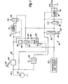
- a hydraulically actuated clutch 10 in particular a driving clutch, with a lubrication circuit 12, which also acts as a cooling circuit, and a likewise hydraulically actuated second clutch 14, in particular a PTO clutch, with a lubrication circuit 16 , which also acts as a cooling circuit.
- the clutch 10 and the second clutch 14 as well as them assigned lubrication circuits 12 and 16 are operated via a control system 18.
- the control system 18 includes a pump 20 which applies a system pressure to a control valve 24 via a main circuit 22, the control valve 24 being actuated by means of a pedal 25 and supplying the pressure built up to the clutch 10 via an actuating circuit 26.
- the pump 20 also builds a system pressure in a control valve 28 that controls the actuation pressure supplied to the second clutch 14.
- the control system 18 is also equipped with a lubricant source 30 which supplies lubricants, in particular lubricating oil, to the lubrication circuits 12 and 16 via a valve 32 according to the invention for the clutch 10 and a reducing valve 34 for the second clutch 14.
- lubricant is also supplied to the lubrication circuits 12 and 16 via control valves 36 and 38, which are opened by the clutch 10 or the pressure applied to the second clutch 14 and closed via a centrifugal governor.
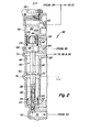
- valve 32 has a housing 40 with an unspecified valve bore, the valve bore being subdivided into an area of larger diameter 42 and an area of smaller diameter 44, and a sliding and sealing hollow valve slide 46 in itself records. Bars 48, 50 and 52 are provided on the valve slide 46, an annular groove being screwed into each of the bars 48 and 52, into which O-rings 54 and 56 are inserted for sealing purposes.
- the webs 48 and 52 function as pressure-sensitive triggering devices or control surfaces and have diameters of different sizes, the web 48 having the larger diameter. Dement speaking, the assignment of the webs 48 and 52 to the areas of larger and smaller diameters 42 and 44 is also selected.
- One end of the housing 40 is closed by a plug 58, as a result of which a pilot chamber 60 is formed between the plug 58 and the valve slide 46, to which the actuating pressure for the clutch 10 is supplied from the control valve 24 via an opening 62.
- An inlet opening 64 and a groove 66 feed lubricant from the lubricant source 30 to the area of larger diameter 42 of the valve bore.
- An outlet opening 68 and a groove 70 connect the larger diameter area 42 of the valve bore to the lubrication circuits 12 and 16 via the control valves 36 and 38.
- an outlet opening 72 and a groove 74 connect the larger and smaller diameter areas 42 and 44 to a collecting container.
- valve 32 is a normally closed two-position valve, which is controlled on the one hand by the actuating pressure applied to the coupling 10 and acting on the web 48 and on the other hand by the system pressure prevailing in the main circuit 22 which acts on the web 52 becomes.
- a shaft 92 extends beyond the web 48 in the direction of the plug 58.
- a hollow, cylindrical element ie a sleeve 94, is slidably mounted on the shaft 92 via a collar 96 which is open on the inside and surrounds the shaft 92 .
- a snap ring or stop 98 holds the sleeve 94 axially on the shaft 92.
- the sleeve 94 is pressed against the stop 98 by means of a spring 100, a distance of approximately 3 mm remaining between the sleeve 94 and the web 48.
- the sleeve 94 protrudes over the shaft 92 so that when the valve spool 46 is moved towards the plug 58, the sleeve 94 first strikes the plug 58 and then the sleeve 94 is moved away from the stop 98 so that the spring 100 is compressed until the sleeve 94 abuts the web 48.
- the pressure from the control valve 24 is high, the clutch 10 is engaged, and the valve 32 is in its closed position, as shown in the drawing, and no lubricant flows to the lubrication circuits 12 or 16.
- valve slide 46 When the system pressure has built up in the pilot chamber 60, the valve slide 46 is moved downward with reference to FIG. 2, specifically because of the area difference between the upper web 48 and the lower web 52. This downward movement causes the Web 52 moves against the system pressure so that lubricant is forced through the screen 84 and the throttles 86 and 88.
- the throttles 86 and 88 cause the downward movement to proceed slowly, which is why the valve 32 takes its closed position only after a predeterminable time and could therefore be referred to as a clutch lubrication reduction delay valve. Accordingly, the lubricant flow continues for a certain time after the clutch 10 is engaged again, that is, until the valve 32 has assumed its closed position.
- the cross-sectional areas of the webs 48 and 52 as well as the size of the throttles 86 and 88 can be changed in order to determine the delay time, that is to say the time in which the lubrication continues after the clutch 10 has been re-engaged.
- This feature of the deceleration is of great advantage because it provides additional lubrication between frequent gear changes of the clutch 10 and thus prevents damage due to excessive heat generation.
- the termination of the lubrication process after clutch 10 is engaged increases the economy of control system 18 as well as clutch 10 under normal conditions.
- this control system 18 provides system pressure in the event of damage to clutch 10 engagement circuit 26 the valve 32 urges it into its open position, so that the lubrication then begins and the possibly slipping clutch 10 is cooled and lubricated.
- the reducing valve 34 is a three-position valve (closed-open-closed) which is brought into one of its closed positions by a spring 110 when the actuation pressure for the second clutch 14 coming from the pump 20 via the control valve 28 is low, as is the case the case is when the second clutch 14 is not engaged.
- a spring 110 When the pressure behind the control valve 28 rises to engage the second clutch 14, this pressure moves the reducing valve 34 to its central position, causing lubricant from the lubricant source 30 to the lubrication circuits 12 and 16 is passed through the control valves 34, 36 and 38.
- a spring 112 serves to resist the movement of the reducing valve 34 away from the central, open position of the reducing valve 34 due to the high pressure supplied by the pump 20.
Landscapes
- Engineering & Computer Science (AREA)
- General Engineering & Computer Science (AREA)
- Mechanical Engineering (AREA)
- Physics & Mathematics (AREA)
- Fluid Mechanics (AREA)
- Magnetically Actuated Valves (AREA)
- Electrically Driven Valve-Operating Means (AREA)
- Hydraulic Clutches, Magnetic Clutches, Fluid Clutches, And Fluid Joints (AREA)
- Temperature-Responsive Valves (AREA)
- Sliding Valves (AREA)
- Fluid-Pressure Circuits (AREA)
- Valve-Gear Or Valve Arrangements (AREA)
- Replacement Of Web Rolls (AREA)
- Multiple-Way Valves (AREA)
- Drilling Tools (AREA)
Priority Applications (1)
| Application Number | Priority Date | Filing Date | Title |
|---|---|---|---|
| AT86105658T ATE45413T1 (de) | 1985-05-02 | 1986-04-24 | Ventil. |
Applications Claiming Priority (2)
| Application Number | Priority Date | Filing Date | Title |
|---|---|---|---|
| US06/729,515 US4591129A (en) | 1985-05-02 | 1985-05-02 | Valve seal breakaway device |
| US729515 | 1985-05-02 |
Publications (3)
| Publication Number | Publication Date |
|---|---|
| EP0200160A2 true EP0200160A2 (fr) | 1986-11-05 |
| EP0200160A3 EP0200160A3 (en) | 1987-01-21 |
| EP0200160B1 EP0200160B1 (fr) | 1989-08-09 |
Family
ID=24931405
Family Applications (1)
| Application Number | Title | Priority Date | Filing Date |
|---|---|---|---|
| EP86105658A Expired EP0200160B1 (fr) | 1985-05-02 | 1986-04-24 | Valve |
Country Status (9)
| Country | Link |
|---|---|
| US (1) | US4591129A (fr) |
| EP (1) | EP0200160B1 (fr) |
| JP (1) | JPS61252977A (fr) |
| AT (1) | ATE45413T1 (fr) |
| AU (1) | AU5652786A (fr) |
| BR (1) | BR8601949A (fr) |
| DE (1) | DE3664954D1 (fr) |
| DK (1) | DK204086A (fr) |
| ES (1) | ES8703001A1 (fr) |
Cited By (1)
| Publication number | Priority date | Publication date | Assignee | Title |
|---|---|---|---|---|
| EP0441137A1 (fr) * | 1990-02-06 | 1991-08-14 | Mercedes-Benz Ag | Ensemble de conduites entre un maître-cylindre et un cylindre récepteur d'un embrayage hydraulique placé dans le circuit d'entraînement d'un véhicule à moteur |
Families Citing this family (1)
| Publication number | Priority date | Publication date | Assignee | Title |
|---|---|---|---|---|
| CN100544455C (zh) * | 2004-10-29 | 2009-09-23 | 华亚微电子(上海)有限公司 | 视频信号中的色串检测方法 |
Family Cites Families (4)
| Publication number | Priority date | Publication date | Assignee | Title |
|---|---|---|---|---|
| US3194497A (en) * | 1962-02-12 | 1965-07-13 | Powers Regulator Co | Temperature control system |
| US3742980A (en) * | 1972-04-03 | 1973-07-03 | Sanders Associates Inc | Hydraulic control system |
| US3825033A (en) * | 1973-02-12 | 1974-07-23 | Sanders Associates Inc | Extended range valve system |
| US3866880A (en) * | 1973-10-09 | 1975-02-18 | Caterpillar Tractor Co | Valve assembly having a pressure responsive detent mechanism |
-
1985
- 1985-05-02 US US06/729,515 patent/US4591129A/en not_active Expired - Fee Related
-
1986
- 1986-04-23 AU AU56527/86A patent/AU5652786A/en not_active Abandoned
- 1986-04-24 AT AT86105658T patent/ATE45413T1/de not_active IP Right Cessation
- 1986-04-24 DE DE8686105658T patent/DE3664954D1/de not_active Expired
- 1986-04-24 EP EP86105658A patent/EP0200160B1/fr not_active Expired
- 1986-04-30 ES ES554547A patent/ES8703001A1/es not_active Expired
- 1986-04-30 BR BR8601949A patent/BR8601949A/pt unknown
- 1986-05-01 JP JP61101902A patent/JPS61252977A/ja active Pending
- 1986-05-02 DK DK204086A patent/DK204086A/da not_active Application Discontinuation
Cited By (1)
| Publication number | Priority date | Publication date | Assignee | Title |
|---|---|---|---|---|
| EP0441137A1 (fr) * | 1990-02-06 | 1991-08-14 | Mercedes-Benz Ag | Ensemble de conduites entre un maître-cylindre et un cylindre récepteur d'un embrayage hydraulique placé dans le circuit d'entraînement d'un véhicule à moteur |
Also Published As
| Publication number | Publication date |
|---|---|
| DK204086A (da) | 1986-11-03 |
| EP0200160B1 (fr) | 1989-08-09 |
| ES554547A0 (es) | 1987-01-16 |
| DE3664954D1 (en) | 1989-09-14 |
| JPS61252977A (ja) | 1986-11-10 |
| BR8601949A (pt) | 1987-01-06 |
| ES8703001A1 (es) | 1987-01-16 |
| ATE45413T1 (de) | 1989-08-15 |
| US4591129A (en) | 1986-05-27 |
| EP0200160A3 (en) | 1987-01-21 |
| AU5652786A (en) | 1986-11-06 |
| DK204086D0 (da) | 1986-05-02 |
Similar Documents
| Publication | Publication Date | Title |
|---|---|---|
| DE1580148C3 (de) | Druckreduzierventil fur hydrau hsche Fahrzeug Bremsanlagen | |
| EP0325958B1 (fr) | Clapet à commande hydraulique | |
| EP0200161A2 (fr) | Système de commande | |
| EP0381069A1 (fr) | Manchon d'accouplement pour lignes d'interconnexion hydraulique | |
| EP0191384B1 (fr) | Soupape d'assemblage | |
| DE10037527A1 (de) | Piezoelektrische Einspritzeinrichtung | |
| DE3012409C2 (fr) | ||
| WO1988008086A1 (fr) | Systeme hydraulique de regulation de pression, notamment pour boite de vitesses couplable sous charge de vehicules a moteur | |
| EP0090945A2 (fr) | Arrangement de la commande d'embrayage d'un dispositif de marche en "roue libre" pour un véhicule automobile | |
| DE2413562A1 (de) | Druckmodulator und system hierzu | |
| DE69914827T2 (de) | Schnellkupplung für ein hydraulisches Steuersystem | |
| DE2624013A1 (de) | Rohr- oder schlauchleitungskupplung | |
| EP0200160B1 (fr) | Valve | |
| DE3917404C2 (fr) | ||
| DE102009049246A1 (de) | Kupplungspedalkraftunterstützungseinrichtung | |
| DE19542766B4 (de) | Arbeitszylinder | |
| DE102015207793B4 (de) | Drosseleinheit zum Drosseln von Fluid in einer hydraulischen Strecke einer hydraulisch betätigbaren Kupplung | |
| DE2801627A1 (de) | Ventil zum schutz von unbeabsichtigten druckaenderungen in rohrleitungssystemen | |
| DE4012481A1 (de) | Ventilvorrichtung mit einem hydraulisch entsperrbaren rueckschlagventil fuer hydraulische systeme des bergbaus, wie vor allem fuer hydraulische ausbausysteme | |
| DE2212679C3 (de) | Hydraulische Schaltvorrichtung für Lastschaltgetriebe mit Sicherung gegen Fehlschaltungen | |
| DE3005703C2 (fr) | ||
| DE3006530A1 (de) | Hydraulisches blockier- oder halteventil | |
| DE69005823T2 (de) | Elektrohydraulische vorrichtung zur betätigung des einkuppelns eines motorfahrzeuges od.dgl. | |
| DE19918788A1 (de) | Hydraulisches Betätigungssystem | |
| DE3048814C2 (fr) |
Legal Events
| Date | Code | Title | Description |
|---|---|---|---|
| PUAI | Public reference made under article 153(3) epc to a published international application that has entered the european phase |
Free format text: ORIGINAL CODE: 0009012 |
|
| AK | Designated contracting states |
Kind code of ref document: A2 Designated state(s): AT BE DE FR GB IT NL SE |
|
| PUAL | Search report despatched |
Free format text: ORIGINAL CODE: 0009013 |
|
| AK | Designated contracting states |
Kind code of ref document: A3 Designated state(s): AT BE DE FR GB IT NL SE |
|
| 17P | Request for examination filed |
Effective date: 19870710 |
|
| 17Q | First examination report despatched |
Effective date: 19880629 |
|
| ITF | It: translation for a ep patent filed | ||
| GRAA | (expected) grant |
Free format text: ORIGINAL CODE: 0009210 |
|
| AK | Designated contracting states |
Kind code of ref document: B1 Designated state(s): AT BE DE FR GB IT NL SE |
|
| REF | Corresponds to: |
Ref document number: 45413 Country of ref document: AT Date of ref document: 19890815 Kind code of ref document: T |
|
| GBT | Gb: translation of ep patent filed (gb section 77(6)(a)/1977) | ||
| REF | Corresponds to: |
Ref document number: 3664954 Country of ref document: DE Date of ref document: 19890914 |
|
| ET | Fr: translation filed | ||
| PG25 | Lapsed in a contracting state [announced via postgrant information from national office to epo] |
Ref country code: AT Effective date: 19900424 |
|
| PG25 | Lapsed in a contracting state [announced via postgrant information from national office to epo] |
Ref country code: SE Effective date: 19900425 |
|
| PG25 | Lapsed in a contracting state [announced via postgrant information from national office to epo] |
Ref country code: BE Effective date: 19900430 |
|
| PLBE | No opposition filed within time limit |
Free format text: ORIGINAL CODE: 0009261 |
|
| STAA | Information on the status of an ep patent application or granted ep patent |
Free format text: STATUS: NO OPPOSITION FILED WITHIN TIME LIMIT |
|
| 26N | No opposition filed | ||
| BERE | Be: lapsed |
Owner name: DEERE & CY Effective date: 19900430 |
|
| PG25 | Lapsed in a contracting state [announced via postgrant information from national office to epo] |
Ref country code: NL Effective date: 19901101 |
|
| NLV4 | Nl: lapsed or anulled due to non-payment of the annual fee | ||
| PGFP | Annual fee paid to national office [announced via postgrant information from national office to epo] |
Ref country code: GB Payment date: 19910313 Year of fee payment: 6 |
|
| PGFP | Annual fee paid to national office [announced via postgrant information from national office to epo] |
Ref country code: FR Payment date: 19910415 Year of fee payment: 6 |
|
| PGFP | Annual fee paid to national office [announced via postgrant information from national office to epo] |
Ref country code: DE Payment date: 19910624 Year of fee payment: 6 |
|
| PG25 | Lapsed in a contracting state [announced via postgrant information from national office to epo] |
Ref country code: GB Effective date: 19920424 |
|
| GBPC | Gb: european patent ceased through non-payment of renewal fee | ||
| PG25 | Lapsed in a contracting state [announced via postgrant information from national office to epo] |
Ref country code: FR Effective date: 19921230 |
|
| PG25 | Lapsed in a contracting state [announced via postgrant information from national office to epo] |
Ref country code: DE Effective date: 19930101 |
|
| REG | Reference to a national code |
Ref country code: FR Ref legal event code: ST |
|
| EUG | Se: european patent has lapsed |
Ref document number: 86105658.8 Effective date: 19910116 |
|
| PG25 | Lapsed in a contracting state [announced via postgrant information from national office to epo] |
Ref country code: IT Free format text: LAPSE BECAUSE OF NON-PAYMENT OF DUE FEES;WARNING: LAPSES OF ITALIAN PATENTS WITH EFFECTIVE DATE BEFORE 2007 MAY HAVE OCCURRED AT ANY TIME BEFORE 2007. THE CORRECT EFFECTIVE DATE MAY BE DIFFERENT FROM THE ONE RECORDED. Effective date: 20050424 |