EP0200174B1 - Dispositif pour rincer automatiquement les parties intimes de personnes handicapées physiques après défécation et/ou avoir uriné - Google Patents
Dispositif pour rincer automatiquement les parties intimes de personnes handicapées physiques après défécation et/ou avoir uriné Download PDFInfo
- Publication number
- EP0200174B1 EP0200174B1 EP86105748A EP86105748A EP0200174B1 EP 0200174 B1 EP0200174 B1 EP 0200174B1 EP 86105748 A EP86105748 A EP 86105748A EP 86105748 A EP86105748 A EP 86105748A EP 0200174 B1 EP0200174 B1 EP 0200174B1
- Authority
- EP
- European Patent Office
- Prior art keywords
- urination
- defecation
- timer
- rinsing liquid
- nozzle
- Prior art date
- Legal status (The legal status is an assumption and is not a legal conclusion. Google has not performed a legal analysis and makes no representation as to the accuracy of the status listed.)
- Expired
Links
- 230000027939 micturition Effects 0.000 title claims description 91
- 230000013872 defecation Effects 0.000 title claims description 89
- 239000007788 liquid Substances 0.000 claims description 56
- XLYOFNOQVPJJNP-UHFFFAOYSA-N water Substances O XLYOFNOQVPJJNP-UHFFFAOYSA-N 0.000 claims description 55
- 238000007599 discharging Methods 0.000 claims description 21
- 210000000436 anus Anatomy 0.000 claims description 20
- 210000003708 urethra Anatomy 0.000 claims description 14
- 230000007257 malfunction Effects 0.000 claims description 10
- XEEYBQQBJWHFJM-UHFFFAOYSA-N Iron Chemical compound [Fe] XEEYBQQBJWHFJM-UHFFFAOYSA-N 0.000 claims description 8
- 210000002700 urine Anatomy 0.000 claims description 8
- 210000003608 fece Anatomy 0.000 claims description 7
- 229910052742 iron Inorganic materials 0.000 claims description 4
- 238000010992 reflux Methods 0.000 claims description 3
- 238000005406 washing Methods 0.000 claims description 3
- 238000004078 waterproofing Methods 0.000 claims description 3
- 239000000463 material Substances 0.000 claims description 2
- 230000001932 seasonal effect Effects 0.000 claims description 2
- 239000008237 rinsing water Substances 0.000 description 5
- 239000002699 waste material Substances 0.000 description 4
- 230000008933 bodily movement Effects 0.000 description 2
- 210000001217 buttock Anatomy 0.000 description 2
- 238000010586 diagram Methods 0.000 description 2
- 238000001035 drying Methods 0.000 description 2
- 230000029142 excretion Effects 0.000 description 2
- 239000000853 adhesive Substances 0.000 description 1
- 230000001070 adhesive effect Effects 0.000 description 1
- 230000002401 inhibitory effect Effects 0.000 description 1
- 238000012986 modification Methods 0.000 description 1
- 230000004048 modification Effects 0.000 description 1
- 238000012856 packing Methods 0.000 description 1
- 210000003899 penis Anatomy 0.000 description 1
- 238000010792 warming Methods 0.000 description 1
- 238000003466 welding Methods 0.000 description 1
Images


Classifications
-
- A—HUMAN NECESSITIES
- A61—MEDICAL OR VETERINARY SCIENCE; HYGIENE
- A61F—FILTERS IMPLANTABLE INTO BLOOD VESSELS; PROSTHESES; DEVICES PROVIDING PATENCY TO, OR PREVENTING COLLAPSING OF, TUBULAR STRUCTURES OF THE BODY, e.g. STENTS; ORTHOPAEDIC, NURSING OR CONTRACEPTIVE DEVICES; FOMENTATION; TREATMENT OR PROTECTION OF EYES OR EARS; BANDAGES, DRESSINGS OR ABSORBENT PADS; FIRST-AID KITS
- A61F5/00—Orthopaedic methods or devices for non-surgical treatment of bones or joints; Nursing devices ; Anti-rape devices
- A61F5/44—Devices worn by the patient for reception of urine, faeces, catamenial or other discharge; Colostomy devices
-
- A—HUMAN NECESSITIES
- A61—MEDICAL OR VETERINARY SCIENCE; HYGIENE
- A61G—TRANSPORT, PERSONAL CONVEYANCES, OR ACCOMMODATION SPECIALLY ADAPTED FOR PATIENTS OR DISABLED PERSONS; OPERATING TABLES OR CHAIRS; CHAIRS FOR DENTISTRY; FUNERAL DEVICES
- A61G9/00—Bed-pans, urinals or other sanitary devices for bed-ridden persons; Cleaning devices therefor, e.g. combined with toilet-urinals
-
- A—HUMAN NECESSITIES
- A61—MEDICAL OR VETERINARY SCIENCE; HYGIENE
- A61G—TRANSPORT, PERSONAL CONVEYANCES, OR ACCOMMODATION SPECIALLY ADAPTED FOR PATIENTS OR DISABLED PERSONS; OPERATING TABLES OR CHAIRS; CHAIRS FOR DENTISTRY; FUNERAL DEVICES
- A61G7/00—Beds specially adapted for nursing; Devices for lifting patients or disabled persons
- A61G7/02—Beds specially adapted for nursing; Devices for lifting patients or disabled persons with toilet conveniences, or specially adapted for use with toilets
-
- A—HUMAN NECESSITIES
- A61—MEDICAL OR VETERINARY SCIENCE; HYGIENE
- A61G—TRANSPORT, PERSONAL CONVEYANCES, OR ACCOMMODATION SPECIALLY ADAPTED FOR PATIENTS OR DISABLED PERSONS; OPERATING TABLES OR CHAIRS; CHAIRS FOR DENTISTRY; FUNERAL DEVICES
- A61G2203/00—General characteristics of devices
- A61G2203/30—General characteristics of devices characterised by sensor means
- A61G2203/46—General characteristics of devices characterised by sensor means for temperature
Definitions
- This invention relates to a device for automatic rinsing of private parts after defecation and/or urination. More particularly, it relates to a device for rinsing of private parts at the time of defecation and/or urination of physically disabled persons, including the aged and patients.
- sensors are provided to the toilet bowl for sensing the defecation and/or urination and the rinsing liquid is discharged for a predetermined time with the aid of a timer for rinsing the private parts of the user such as anus.
- these known devices are adapted for healthy persons who can sit on the toilet during rinsing. These devices are not effective with physically disabled persons whose bodily movements are not at their will since they cannot get their private parts rinsed sufficiently. If they should try to wash their private parts at any rate, the rinsing liquid such as warm water will be scattered occasionally without being used effectively for rinsing.
- US-A-3,626,941 discloses a device for collecting urine and faeces excreted from a user's body and for rinsing the private parts of said user's body after urination and defecation, said device, in its main part, including means for temporarily securing the user's body to the device while covering private parts, means for collecting urine and faeces excreted from the user's body, inlet ports for introducing and drainage ports for discharging a rinsing liquid and means for releasing the rinsing liquid for a predetermined time towards the private parts of the user's body.
- this device has to be started by a manually activated timer to provide cleansing and drying of the private parts.
- an automatic urine collecting system which includes an automatic rinsing system for the corresponding parts of the user's body, said system including means for sensing urination to thereby release the rinsing liquid automatically.
- discharge means for faeces are not provided by the system disclosed in said document.
- the present invention provides device for collecting urine and faeces excreted from a user's body and for automatically rinsing private parts of said user's body after the urination and/or defecation comprising a main body including means for temporarily securing the user's body to the device while covering private parts such as anus and urethra, an inlet port for introducing a rinsing liquid for rinsing the private parts, a drainage port for discharging the used rinsing liquid with discharge materials out of the main body; and means for releasing the rinsing liquid for a predetermined time towards the private parts such as anus and urethra, said device being characterized by said main body including means for sensing urination and defecation, means being provided for discriminating defecation and urination from each other on the basis of the output signals from said sensor means, and by said release of the rinsing liquids being carried out on the basis of
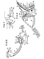
- the main body 1 of the rinsing device has an upper opening water-tightly contacting with private parts including a defecation opening (anus) and a urination opening (urethra) of the user's body. It has four upper attachment members 11 for engagement with four belts 3 acting as means for temporarily attaching the device to the user's body.
- a safety cover 6 for inhibiting water leakage is mounted integrally to the main body 1 at a juncture 12 along with a lower base 7 and a spring 8 in such a manner that the upper opening of the main body 1 will overlie not only the anus which is the opening for defecation but also the urethra which is the opening for urination of the female user.
- the cover 6 is comprised of a base joint section 5 and an elongated trough 6 extending from the joint section.
- the spring 8 is adapted to press the water leakage safety cover 6 into intimate fitting with the private portions of the user's body.
- a shock-absorbing bellows-like member 10 is provided at the upper portion of the cover 6 which is the portion to contact with the user's body, in such a manner that the bellows-like member 10 is contiguous to a water-proofing member 9 provided on an upper frame 13 at the upper opening of the main body 1.
- the bellows-like member 10 is used as a packing to water-tightly seal the contacting portion with the user's body to prevent the rinsing liquid from leaking to outside of the rinsing device in cooperation with the water-proofing cushioning member 9.
- a reflux member or deflector 15 adapted to guide the rinsing liquid from the rinse liquid nozzle towards the urethral opening for rinsing the private portion including the urethral opening to then return the used rinsing liquid towards the toilet bowl.
- a temperature and/or humidity sensor 16 to sense the urination.
- the output signals from the sensor are coupled to a defecation/urination discriminating unit which will be described.
- a guide piping 14 is adapted to guide the rinsing water from the nozzle towards the urethral opening and secured to the reflux member 15 by welding or with an adhesive.
- the rinsing water may be supplied from the water main directly, the water supplied from the main may be stored in a water tank 20 and then supplied to a water heater 21 where it is heated to a suitable temperature and transmitted as rinsing warm water through a piping 22.
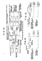
- a nozzle 24 is disposed in a water inlet port 23 and provided at predetermined distances with a plurality of iron segments 25-1, 25-2 and 25-3 operatively associated with timer-electro-magnets 26-1, 26-2, 26-3, 26-4 and 26-5. These electro-magnets are excited in dependence upon urination and/or defecation as sensed by the aforementioned sensors for shifting the nozzle 24 towards the opening for defecation and/or that for urination. Referring more specifically to Figs. 14 and 17, in case of urination, an output signal indicating the state of urination from changes in temperature or humidity rises sharply through amplifier 28 of a malfunction safety unit 31.
- the amplified signal is compared in a comparator 29 with a voltage previously set on a potentiometer 30.
- timer 47 is started to produce a signal to command the discharge of rinsing water to take place after lapse of a certain time, as in 90 seconds after the end of urination, as shown in Fig. 16.
- the numeral 32 denotes a variable resistor for calibrating the operating temperature of the temperature sensor 16 of the sensor unit 33 as a function of seasonal changes in ambient atmospheric temperature.
- the signal from the comparator 29 of the unit 31 is passed through AND gate 35 and NAND a circuit 36 of a defecation/urination discriminating unit 34 in order to recognize urination.
- a nozzle-shifting electro-magnet for urination- timer-magnet exciting circuit 45 By the operation of a nozzle-shifting electro-magnet for urination- timer-magnet exciting circuit 45, a pair of electro-magnets 26-5 on both sides of the main body 1 are excited for shifting the nozzle 24 from its normal position facing to the electro-magnet 26-4 in the direction of the guide pipe 14 for holding the nozzle in this position for 20 seconds, see Figs. 2 and 16.
- the signal indicating urination at the defecation/urination discriminating unit 34 causes an electro-magnet, not shown, of the water inlet port 23 to be opened with the aid of a urination timer-magnetic valve circuit 43 for emitting a rinsing liquid at 40 from the nozzle for 25 seconds in the direction of the guide pipe 14, Figs.
- the circuit 45 is fitted with the timer in order that the nozzle will be transferred in the direction of the guide pipe 14 after lapse of 5 seconds since the opening of the electro-magnet 45 for emitting the warm rinsing liquid from the water heater to the private parts of the body, Fig. 16. In this manner, the water which will flow in cold state from the water heater to the nozzle port in winter is not discharged directly to the private portions of the user's body.
- the signal that has sensed the state of urination at the pressure sensor 19 of the sensor unit 33 ceases for 60 seconds in order to wait for complete cessation of defecation with the aid of the timer 37 of the malfunction safety unit 31.
- the signal is then passed through AND gate 35 and NAND b gate 44 of the unit 34 to recognize the defecation to then excite the electro-magnets 26-1, 26-2 and 26-3 with the aid of a nozzle-shifting electro-magnet-timer-magnet exciting circuit 46 for shifting the nozzle 24 in the direction of the anus which is the opening for defecation so that the nozzle 24 will remain in this position for about 60 seconds, see Fig. 2.
- the signal indicative of the state of defecation in the defecation/urination discriminating unit 34 causes the magnetic valve, not shown, of the water inlet port 23 to be opened with the aid of a defecation timer-magnetic valve circuit 39 of a rinsing liquid discharging unit 38 for discharging the rinsing liquid at 40 for 65 seconds from the nozzle to the anus which is the opening of defecation.
- the nozzle-shifting electro-magnet for defecation-timer-magnet exciting circuit can be designed, as shown in Fig. 15, to shift the nozzle in 5 seconds after the opening of the magnetic valve to prevent the cold water from being discharged to the private portions.
- the signals indicative of both the defecation and urination at the pressure sensor 19 and the temperature or humidity sensor 16 of the sensor unit 33 are passed through the malfunction safety unit 31 to recognize both the defecation and urination at the AND gate 35 of the discrimination unit 34.
- the resulting signal is transmitted via nozzle-shifting electro-magnet-timer-magnet exciting circuit 41 for sequentially exciting electro-magnets 26-5, 26-1, 26-2 and 26-3 with the aid of the timer in such a manner that, in 90 seconds after the urination signal has first reached a predetermined voltage value, the nozzle is directed towards the opening for urination and a rinsing liquid is discharged for 25 seconds for rinsing the opening for urination for 20 seconds, and that, in 60 seconds after the end of defecation, the nozzle is directed towards the anus and the magnetic valve, not shown, is opened by the defecation/urination timer-magnetic valve circuit 42 of the rinsing liquid discharging unit 38 to discharge the rinsing liquid for 65 seconds.
- the rinsing liquid is to be discharged for 5 seconds before nozzle shifting so as not to cause cold water to be discharged to the private portions of the user's body.
- Fig. 5 shows the inventive automatic rinsing device adapted for male users.
- the device shown in Fig. 5 differs from the embodiment shown in Figs. 1 through 4 in that the leakage safety cover 6 is a long tube in which a temperature or humidity sensor 16 for sensing the urination and a guide pipe 14 are led closely to a washing pouch 48 into which the opening of male user's urethral opening is introduced and that a fastener 49 including a hook, loop and a string for attachment to a penis is mounted to the washing pouch 48.
- the present embodiment is similar to the device for the female user described in connection with Figs. 1 through 4.
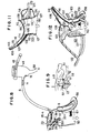
- Fig. 6 shows an automatic rinsing device which is used by female users as the embodiment shown in Fig. 1.
- the present embodiment differs from the device shown in Fig. 1 in that it is adapted to be used by bedridden patients.
- the rinsing device of the present device has a water inlet port 23 from the water supply system at the front lower side of the main body 1 and a water discharge port 50 communicating with toilet bowl 17 (Fig. 7) at the rear side of the main body 1.
- the timer-nozzle-shifting electro-magnets 26-1, 26-2, 26-3, 26-4 and 26-5 of the defecation/urination discriminating unit 34 and the nozzle 24 are provided to the water inlet port 23.
- timer-magnet exciting circuit 45 is operatively associated with the timer-nozzle-shifting electro-magnet for urination 26-4.
- the nozzle-shifting electro-magnet for defecation-timer-magnet exciting circuit 46 is operatively associated with the timer-nozzle-shifting electro-magnet for defecation 26-5
- the nozzle-shifting electro-magnet for defecation/urination-timer-magnet exciting circuit 41 is operatively associated with the timer-nozzle-shifting electro-magnets for defecation/urination 26-4 and 26-5, with the timer-nozzle-shifting electro-magnets 26-1, 26-2 and 26-3 indicating the normal position for the nozzle 24.
- the numeral 56 denotes a water deflector below the user's buttock and the numeral 57 a spring adapted to fit the water-cushioning member 9 with the buttock.
- Fig. 7 shows the state in which the present rinsing device is mounted in position to permit the user to urinate on a seat 52 of the toilet bowl mounted on the bed.
- the numeral 53 denotes a front side warm air discharge port from an air heater, not shown, and the numeral 54 a rear side warm air discharge port from an air heater 55 adapted for drying the private parts after rinsing.
- Fig. 8 shows an automatic rinsing device for males similar to the embodiment shown in Fig. 5.
- the device of Fig. 8 differs from the device shown in Fig. 5 in that it is used by bedridden users.
- the device shown in Fig. 8 has a water inlet port 23 from the water supply device at the front lower side of the main body 1 and a water discharge port 50 communicating with the toilet bowl 17 at the rear side of the main body 1.
- the device shown in Fig. 8 also has a nozzle 24, timer-nozzle-shifting electro-magnets 26-1, 26-2, 26-3, 26-4and 26-5, and a drain tube 58 in the pouch 48 for draining the used rinse water and urine into the toilet bowl 17.
- the parts used in the device of Fig. 8 are configured similarly to the corresponding parts used in Fig. 6.
- Fig. 9 shows the state in which the device shown in Fig. 8 is mounted in position to permit the user to defecate on the seat of the toilet bowl 17 mounted on the bed.
- Fig. 10 shows the state in which the device shown in Fig. 1 or 5 is used in conjunction with a reclining type bed 51 to permit the user to defecate with a part of the bed used as a backrest.
- the numeral 61 designates a tank in which is stored the waste material delivered from the toilet bowl 17 through a waste material drainage pipe 62 and a vacuum unit, not shown.
- the reclining can be achieved by extending or contracting a pair of cylinders 59 and 60 by the operation of a driving circuit, not shown, on the basis of the output signals from the sensor 33 at the time of urination and/or defecation, Figs. 1 and 5.
- the automatic rinsing device according to a modified embodiment of the present invention will be explained by referring to Figs. 11 through 13.
- the device shown in Fig. 11, corresponds to the device shown in Figs. 1 to 5.
- the device shown in Fig. 12 corresponds to the device shown in Fig. 6, while the device shown in Fig. 13 corresponds to the device shown in Fig. 8.
- the devices shown in Figs. 11, 12, and 13 are similar to the devices shown in Figs. 1-5, 6 and 8 of the first embodiment except that stationary nozzles 124, 124' are used in place of the movable nozzle 24 provided with the iron segments 25-1,25-2 and 25-3 and the timer-electro-magnets 26-1, 26-2, 26-3, 26-4 and 26-5.
- the 15-second timer of the magnetic valve a for urination is actuated to turn on the magnetic valve a for urination to discard the cold rinsing water from the water heater 121 (Fig. 19) to the valve into the toilet bowl 17, see (i).
- the magnetic valve b for urination is turned on for 10 seconds by the 10-second timer of the magnetic valve b for urination for emitting the rinsing liquid to the private parts, see (ii), the valves a and b being then turned off, see (iii). In this manner, there may be avoided a situation in which the cold water between the valve and the water heater is emitted directly to the private parts during the aforementioned 5 seconds in winter.
- Figs. 11, 18A, B and C the water passage between the water heater 121 and the valve is divided into a defecation nozzle 124 and a urination nozzle 124' with the use of a bifurcated pipe.
- the piping for defecation and that for urination may be directly divided from the water heater 121.
- Fig. 20 shows a further embodiment in which a heat reserving device 125 such as a heater is provided in the water passage between the water heater 121 and the valve.
- the timer for the magnetic valve c for urination may be turned on for 10 seconds by the operation of the circuit 145 to turn on the magnetic valve c for urination, Fig. 20A, so that the warm water will be discharged at 140 to the private parts of the user's body.
- the signal from the pressure sensor 119 of the sensor unit 133 indicating defecation, Fig. 21, is transmitted to the malfunction safety circuit 137 of the malfunction safety unit 131 where the signal ceases for 60 seconds in order to wait for complete cessation of defecation.
- the output signal from the unit 131 is then transmitted through the AND gate 135 and NAND b gate 144 of the defecation/urination discriminating unit 134 in order to ascertain excretion of faeces.
- the signal from the unit 134 indicating defecation causes the magnetic valves a and b between the water supply unit and the water inlet port 123 to be opened with the aid of the defecation timer-magnetic valve circuit 139 of the rinse liquid discharging unit 138 to discharge the rinsing liquid at 140 for 60 seconds from the nozzle towards the anus which is the opening for defecation.
- Figs. 18A(a), 18B(b), 18C(c) and 23 it is also possible in this case to turn on the magnetic valve for defecation a only for discarding the cold rinsing liquid between the water heater 121 and the valve for 5 seconds into the toilet bowl 17, Fig.
- the magnetic valve c for defecation may be activated for 60 seconds by the operation of the defecation timer-magnetic valve circuit 139 to turn on the valve c, Fig. 20(B), to discharge warm water to the private parts at 140.
- the signals from the pressure sensor 119 and the temperature or humidity sensor 116 of the sensor unit 133 indicating both defecation and urination, Fig. 24, are transmitted via malfunction safety unit 131 to ascertain excretion of both faeces and urine by the AND gate 135 of the discriminating unit 134.
- the output signal from the unit 134 indicating both defecation and urination is transmitted to the defecation/urination timer-magnetic valve 142 of the rinse liquid discharging unit 138.
- the defecation/urination timer-magnetic valve circuit 142 operates as follows: The signal from the urination sensor causes the magnetic valves a and b for urination between the water supply device and the water inlet port 123 to be turned on to permit the rinse liquid to be discharged for 10 seconds from the nozzle towards the guide pipe 114. The signal from the defecation sensor 119 causes magnetic valves for defecation a and b to be turned on to permit the rinsing liquid to be discharged at 140 from the nozzle towards the anus for 60 seconds after lapse of 60 seconds since the end of defecation.
- the magnetic valve b for urination or defecation is turned on 5 seconds before the valve a to drain cold water into the toilet bowl 17 instead of discharging it towards the private parts.
- the timer-magnetic valve circuit 142 may be so designed that the timer of each magnetic valve c for defecation or urination is started in 60 seconds after the end of defecation to turn on the magnetic valves for urination and defecation c, c connecting to the nozzle 124 for defecation and to the nozzle 124' for urination, so as to discharge warm water at 140 towards the private parts.
Landscapes
- Health & Medical Sciences (AREA)
- Veterinary Medicine (AREA)
- Life Sciences & Earth Sciences (AREA)
- Animal Behavior & Ethology (AREA)
- General Health & Medical Sciences (AREA)
- Public Health (AREA)
- Nursing (AREA)
- Epidemiology (AREA)
- Orthopedic Medicine & Surgery (AREA)
- Engineering & Computer Science (AREA)
- Biomedical Technology (AREA)
- Heart & Thoracic Surgery (AREA)
- Vascular Medicine (AREA)
- Orthopedics, Nursing, And Contraception (AREA)
- Accommodation For Nursing Or Treatment Tables (AREA)
Claims (35)
Priority Applications (1)
| Application Number | Priority Date | Filing Date | Title |
|---|---|---|---|
| AT86105748T ATE47663T1 (de) | 1985-04-27 | 1986-04-25 | Vorrichtung zum automatischen spuelen der intimen teile von koerperbehinderten personen nach dem stuhlgang und/oder urinieren. |
Applications Claiming Priority (4)
| Application Number | Priority Date | Filing Date | Title |
|---|---|---|---|
| JP91743/85 | 1985-04-27 | ||
| JP60091743A JPH0244224B2 (ja) | 1985-04-27 | 1985-04-27 | Haibenyojidosenjosochi |
| JP125138/85 | 1985-06-11 | ||
| JP60125138A JPS61284222A (ja) | 1985-06-11 | 1985-06-11 | 排便用自動洗滌装置 |
Publications (3)
| Publication Number | Publication Date |
|---|---|
| EP0200174A2 EP0200174A2 (fr) | 1986-11-05 |
| EP0200174A3 EP0200174A3 (en) | 1987-12-02 |
| EP0200174B1 true EP0200174B1 (fr) | 1989-11-02 |
Family
ID=26433187
Family Applications (1)
| Application Number | Title | Priority Date | Filing Date |
|---|---|---|---|
| EP86105748A Expired EP0200174B1 (fr) | 1985-04-27 | 1986-04-25 | Dispositif pour rincer automatiquement les parties intimes de personnes handicapées physiques après défécation et/ou avoir uriné |
Country Status (4)
| Country | Link |
|---|---|
| US (1) | US4791686A (fr) |
| EP (1) | EP0200174B1 (fr) |
| KR (1) | KR890002017B1 (fr) |
| DE (1) | DE3666664D1 (fr) |
Cited By (1)
| Publication number | Priority date | Publication date | Assignee | Title |
|---|---|---|---|---|
| DE102010053690A1 (de) * | 2010-12-08 | 2012-06-14 | EMOTEC Aktiengesellschaft Elektro-, Metall- und Oberflächentechnik | Apparatur zur sicheren und hygienischen Entsorgung menschlicher Stoffwechselprodukte von bettlägerigen Personen |
Families Citing this family (100)
| Publication number | Priority date | Publication date | Assignee | Title |
|---|---|---|---|---|
| JPH02126629U (fr) * | 1989-03-28 | 1990-10-18 | ||
| EP0494488A1 (fr) * | 1991-01-07 | 1992-07-15 | Kawasaki, Seiji | Système pour écarter des excréments |
| KR960000389B1 (ko) * | 1993-06-07 | 1996-01-06 | 이성규 | 휴대용 변기 |
| US5842237A (en) * | 1996-02-15 | 1998-12-01 | Lotecon, Llc | Convertible bed/chair with waste disposal |
| JP3097029B2 (ja) * | 1996-10-09 | 2000-10-10 | 多摩重起建設株式会社 | 水洗便器付き介護用ベッド |
| ES2136543B1 (es) * | 1997-05-08 | 2000-07-01 | Roman Lopez Francisco | Dispositivo portatil anatomico sanitario de defecacion y orina. |
| JPH1147180A (ja) * | 1997-07-29 | 1999-02-23 | Niles Parts Co Ltd | 排泄物処理装置 |
| EP1656922A3 (fr) * | 1998-05-12 | 2008-11-05 | Teruo Kitamura | Dispositif de lavage du séant d'un patient |
| JP3077085B1 (ja) * | 1999-02-16 | 2000-08-14 | ナイルス部品株式会社 | 排泄物処理装置 |
| JP2001112802A (ja) * | 1999-10-18 | 2001-04-24 | Niles Parts Co Ltd | 排泄物処理装置 |
| DE19956722A1 (de) | 1999-11-25 | 2001-06-13 | Helmut Utz | Toiletteneinrichtung, insbesondere für bettlägerige Personen |
| WO2002013736A1 (fr) * | 2000-08-17 | 2002-02-21 | Hanmedics Co., Ltd. | Appareil collecteur d'urine personnel avec systeme de bidet |
| JP3388734B1 (ja) * | 2001-11-22 | 2003-03-24 | 株式会社ビルメン鹿児島 | 介護用便器システム |
| US6641567B1 (en) * | 2002-01-24 | 2003-11-04 | Maryjane Williams | Incontinence diaper and receptacle apparatus |
| US20050070860A1 (en) * | 2003-09-30 | 2005-03-31 | Teruo Kitamura | Device for disposing excrements |
| WO2005041829A1 (fr) * | 2003-10-31 | 2005-05-12 | Toshiharu Honda | Appareil de traitement d'excrements |
| EP1873318A4 (fr) * | 2005-04-11 | 2009-05-06 | Zhenhua Liu | Dispositif de traitement automatique des rejets humains |
| US20060247604A1 (en) * | 2005-04-29 | 2006-11-02 | Bruno Roy R | Lavage chair and method of use |
| KR20070107532A (ko) * | 2006-05-03 | 2007-11-07 | 주식회사 노비타 | 온수세정기의 자동 물내림 장치와 그 제어방법 |
| KR100735833B1 (ko) * | 2006-06-26 | 2007-07-06 | 주식회사 엘쓰리 | 수세식 간이 소변기 |
| FR2905593B1 (fr) * | 2006-09-13 | 2009-08-21 | Univ Paris Curie | Sous-vetement pour personne incontinente et dispositif de traitement associe a un sous-vetement |
| USD615193S1 (en) | 2007-11-13 | 2010-05-04 | Helmut Utz | Bedpan |
| JP4567757B2 (ja) * | 2008-02-05 | 2010-10-20 | 稔 中村 | 自動排尿便処理装置 |
| ITMI20081705A1 (it) * | 2008-09-26 | 2010-03-27 | Serenum Srl | Macchina elettromedicale autopulente per il lavaggio e l'asciugatura anale genitale delle persone pazienti allettate e per la conseguente eliminazione delle feci e delle urine prodotte dalle stesse persone pazienti non autosufficienti |
| KR100942204B1 (ko) * | 2009-08-11 | 2010-02-11 | 주식회사 큐라코 | 노즐 높이 조절이 가능한 자동 배설물 처리장치 |
| CN101933857B (zh) * | 2010-08-25 | 2012-01-04 | 杭州亿脑智能科技有限公司 | 智能护理机 |
| CN102296686A (zh) * | 2011-06-21 | 2011-12-28 | 东莞市新福乐医疗器械有限公司 | 一种大小便自动处理的方法 |
| CN103306345B (zh) * | 2012-03-06 | 2016-03-30 | 陈润 | 马桶手动通便器 |
| US10390989B2 (en) | 2014-03-19 | 2019-08-27 | Purewick Corporation | Apparatus and methods for receiving discharged urine |
| US10952889B2 (en) | 2016-06-02 | 2021-03-23 | Purewick Corporation | Using wicking material to collect liquid for transport |
| US10226376B2 (en) | 2014-03-19 | 2019-03-12 | Purewick Corporation | Apparatus and methods for receiving discharged urine |
| US11806266B2 (en) | 2014-03-19 | 2023-11-07 | Purewick Corporation | Apparatus and methods for receiving discharged urine |
| US11090183B2 (en) | 2014-11-25 | 2021-08-17 | Purewick Corporation | Container for collecting liquid for transport |
| US11376152B2 (en) | 2014-03-19 | 2022-07-05 | Purewick Corporation | Apparatus and methods for receiving discharged urine |
| CN104173157B (zh) * | 2014-09-09 | 2017-04-26 | 柳丰萍 | 接便器及病床 |
| US10358807B2 (en) * | 2014-11-25 | 2019-07-23 | Shandong Crrc Huateng Environment Co., Ltd. | Suction seat for intelligent nursing toilet bowl |
| JP6533578B2 (ja) * | 2014-12-01 | 2019-06-19 | キュラコ・インコーポレイテッドCURACO,Inc. | 人体対向開口部が形成された男性用モジュールを含む排泄物処理装置 |
| US10702433B2 (en) * | 2015-02-03 | 2020-07-07 | Curaco, Inc. | Excreta disposal apparatus comprising gender-specific module |
| USD928946S1 (en) | 2016-06-02 | 2021-08-24 | Purewick Corporation | Urine receiving apparatus |
| US10973678B2 (en) | 2016-07-27 | 2021-04-13 | Purewick Corporation | Apparatus and methods for receiving discharged urine |
| US10376406B2 (en) | 2016-07-27 | 2019-08-13 | Purewick Corporation | Male urine collection device using wicking material |
| CN106726087A (zh) * | 2017-01-14 | 2017-05-31 | 苏州欧圣电气工业有限公司 | 一种穿戴式护理机工作头 |
| WO2018144463A1 (fr) | 2017-01-31 | 2018-08-09 | Purewick Corporation | Appareil et procédés pour la réception d'urine excrétée |
| TR201721930A2 (tr) * | 2017-12-26 | 2019-07-22 | Aslan Ali Pirli | Fonksiyonel külot atık uzaklaştırma ünitesi |
| AU2019262939A1 (en) | 2018-05-01 | 2020-11-26 | Purewick Corporation | Fluid collection devices, systems, and methods |
| JP7072084B2 (ja) | 2018-05-01 | 2022-05-19 | ピュアウィック コーポレイション | 流体収集装置、関連システム、及び関連方法 |
| EP3787571B1 (fr) | 2018-05-01 | 2022-06-01 | Purewick Corporation | Vêtements de collecte de fluide |
| US11944740B2 (en) | 2018-05-01 | 2024-04-02 | Purewick Corporation | Fluid collection devices, related systems, and related methods |
| EP3787569B1 (fr) | 2018-05-01 | 2025-07-16 | Purewick Corporation | Dispositifs et systèmes de collecte de fluide |
| AU2019262945B2 (en) | 2018-05-01 | 2022-08-25 | Purewick Corporation | Fluid collection devices and methods of using the same |
| CN109044673B (zh) * | 2018-08-26 | 2021-03-16 | 张惠丽 | 一种检测后自动移位、擦拭、烘干而恢复检测功能的检测机构 |
| US10689836B1 (en) | 2018-12-31 | 2020-06-23 | Kelley Simon | Handheld personal perineal cleansing system and methods |
| US11708688B2 (en) | 2018-12-31 | 2023-07-25 | Kelley Simon | Personal perineal cleansing system and methods |
| US11234562B1 (en) | 2018-12-31 | 2022-02-01 | Kelley Simon | Handheld personal perineal cleansing system and methods |
| USD929578S1 (en) | 2019-06-06 | 2021-08-31 | Purewick Corporation | Urine collection assembly |
| CA3143904C (fr) | 2019-06-21 | 2023-11-28 | Purewick Corporation | Dispositifs de collecte de fluide comprenant une zone de fixation de base, et systemes et procedes associes |
| ES2961269T3 (es) | 2019-07-11 | 2024-03-11 | Purewick Corp | Dispositivos y sistemas de recogida de líquido |
| WO2021016026A1 (fr) | 2019-07-19 | 2021-01-28 | Purewick Corporation | Dispositifs de collecte de fluide comprenant au moins un matériau à mémoire de forme |
| EP4051190B1 (fr) | 2019-10-28 | 2024-05-22 | Purewick Corporation | Ensembles de collecte de fluide comprenant un orifice d'échantillon |
| EP4559443A3 (fr) | 2020-01-03 | 2025-06-18 | Purewick Corporation | Dispositifs de collecte d'urine ayant une partie relativement large et une partie allongée et procédés associés |
| WO2021188817A1 (fr) | 2020-03-19 | 2021-09-23 | Purewick Corporation | Ensembles de collecte de fluide comprenant un ou plusieurs éléments d'amélioration du mouvement |
| US12521288B2 (en) | 2020-03-26 | 2026-01-13 | Purewick Corporation | Multi-layer urine capture device and related methods |
| WO2021207621A1 (fr) | 2020-04-10 | 2021-10-14 | Purewick Corporation | Ensembles de collecte de fluide comprenant un ou plusieurs éléments de prévention de fuite |
| US12472090B2 (en) | 2020-04-17 | 2025-11-18 | Purewick Corporation | Female external catheter devices having a urethral cup, and related systems and methods |
| WO2021211801A1 (fr) | 2020-04-17 | 2021-10-21 | Purewick Corporation | Ensembles de collecte de fluide comprenant une barrière imperméable aux fluides comportant une cuvette et une base |
| US12465514B2 (en) | 2020-04-17 | 2025-11-11 | Purewick Corporation | Fluid collection devices, systems, and methods securing a protruding portion in position for use |
| US12491104B2 (en) | 2020-04-20 | 2025-12-09 | Purewick Corporation | Fluid collection devices adjustable between a vacuum-based orientation and a gravity-based orientation, and related systems and methods |
| US12048643B2 (en) | 2020-05-27 | 2024-07-30 | Purewick Corporation | Fluid collection assemblies including at least one inflation device and methods and systems of using the same |
| USD967409S1 (en) | 2020-07-15 | 2022-10-18 | Purewick Corporation | Urine collection apparatus cover |
| US12440371B2 (en) | 2020-08-06 | 2025-10-14 | Purewick Corporation | Fluid collection system including a garment and a fluid collection device |
| US12350187B2 (en) | 2020-08-11 | 2025-07-08 | Purewick Corporation | Fluid collection assemblies defining waist and leg openings |
| EP4210643A1 (fr) | 2020-09-09 | 2023-07-19 | Purewick Corporation | Dispositifs, systèmes et procédés de collecte de fluide |
| US11801186B2 (en) | 2020-09-10 | 2023-10-31 | Purewick Corporation | Urine storage container handle and lid accessories |
| US12156792B2 (en) | 2020-09-10 | 2024-12-03 | Purewick Corporation | Fluid collection assemblies including at least one inflation device |
| US12042423B2 (en) | 2020-10-07 | 2024-07-23 | Purewick Corporation | Fluid collection systems including at least one tensioning element |
| US12569365B2 (en) | 2020-10-21 | 2026-03-10 | Purewick Corporation | Fluid collection assemblies including at least one shape memory material disposed in the conduit |
| US12440370B2 (en) | 2020-10-21 | 2025-10-14 | Purewick Corporation | Apparatus with compressible casing for receiving discharged urine |
| US12257174B2 (en) | 2020-10-21 | 2025-03-25 | Purewick Corporation | Fluid collection assemblies including at least one of a protrusion or at least one expandable material |
| US12208031B2 (en) | 2020-10-21 | 2025-01-28 | Purewick Corporation | Adapters for fluid collection devices |
| US12048644B2 (en) | 2020-11-03 | 2024-07-30 | Purewick Corporation | Apparatus for receiving discharged urine |
| US12070432B2 (en) | 2020-11-11 | 2024-08-27 | Purewick Corporation | Urine collection system including a flow meter and related methods |
| US12245967B2 (en) | 2020-11-18 | 2025-03-11 | Purewick Corporation | Fluid collection assemblies including an adjustable spine |
| US12599495B2 (en) | 2021-01-05 | 2026-04-14 | Purewick Corporation | Male external catheter with attachment interface configured to bias against penis |
| US12268627B2 (en) | 2021-01-06 | 2025-04-08 | Purewick Corporation | Fluid collection assemblies including at least one securement body |
| JP2024503636A (ja) | 2021-01-07 | 2024-01-26 | ピュアウィック コーポレイション | 車椅子に固定可能な尿収集システムおよび関連する方法 |
| EP4349306A3 (fr) | 2021-01-19 | 2024-06-05 | Purewick Corporation | Dispositifs, systèmes et procédés de collecte de fluide à ajustement variable |
| US12178735B2 (en) | 2021-02-09 | 2024-12-31 | Purewick Corporation | Noise reduction for a urine suction system |
| EP4274524B1 (fr) | 2021-02-26 | 2024-08-28 | Purewick Corporation | Dispositif de collecte de fluide configuré comme un dispositif de collecte d'urine masculin |
| US12558472B2 (en) | 2021-03-05 | 2026-02-24 | Purewick Corporation | Portable fluid collection systems with storage and related methods |
| US12551385B2 (en) | 2021-03-05 | 2026-02-17 | Purewick Corporation | Fluid collection assembly including a tube having porous wicking material for improved fluid transport |
| US11938054B2 (en) | 2021-03-10 | 2024-03-26 | Purewick Corporation | Bodily waste and fluid collection with sacral pad |
| US12458525B2 (en) | 2021-03-10 | 2025-11-04 | Purewick Corporation | Acoustic silencer for a urine suction system |
| US12029677B2 (en) | 2021-04-06 | 2024-07-09 | Purewick Corporation | Fluid collection devices having a collection bag, and related systems and methods |
| US12233003B2 (en) | 2021-04-29 | 2025-02-25 | Purewick Corporation | Fluid collection assemblies including at least one length adjusting feature |
| US12251333B2 (en) | 2021-05-21 | 2025-03-18 | Purewick Corporation | Fluid collection assemblies including at least one inflation device and methods and systems of using the same |
| US12324767B2 (en) | 2021-05-24 | 2025-06-10 | Purewick Corporation | Fluid collection assembly including a customizable external support and related methods |
| US12150885B2 (en) | 2021-05-26 | 2024-11-26 | Purewick Corporation | Fluid collection system including a cleaning system and methods |
| US12575960B2 (en) | 2021-06-24 | 2026-03-17 | Purewick Corporation | Urine collection systems having one or more of volume, pressure, or flow indicators, and related methods |
| US12551366B2 (en) | 2021-08-02 | 2026-02-17 | Purewick Corporation | Fluid collection devices having multiple fluid collection regions, and related systems and methods |
| US12594062B2 (en) | 2021-09-08 | 2026-04-07 | Purewick Corporation | Fluid collection assemblies including an extension |
Family Cites Families (14)
| Publication number | Priority date | Publication date | Assignee | Title |
|---|---|---|---|---|
| DE1016904B (de) * | 1953-10-10 | 1957-10-03 | Elektro Therapie M B H Ges | Stuhlartige Darmbadeinrichtung |
| US3626941A (en) * | 1968-08-06 | 1971-12-14 | Donald D Webb | Excretory prosthesis |
| US3757355A (en) * | 1971-09-09 | 1973-09-11 | R Allen | Portable body waste collecting system |
| DE2200033A1 (de) * | 1972-01-03 | 1973-07-19 | Herbert Arnds | Steckbecken |
| DE2325260A1 (de) * | 1972-05-26 | 1973-12-13 | Huyot | Sanitaer-hygienische vorrichtung |
| JPS5330273B2 (fr) * | 1973-05-07 | 1978-08-25 | ||
| GB1563343A (en) * | 1975-11-10 | 1980-03-26 | Combi Co | Urinating receiver |
| US4137579A (en) * | 1977-12-20 | 1979-02-06 | Soler Peter S | Urine drain |
| US4237560A (en) * | 1978-12-28 | 1980-12-09 | Rusco Industries, Inc. | Bidet system and water tank therein |
| JPS5750009Y2 (fr) * | 1979-03-12 | 1982-11-02 | ||
| DE3381050D1 (de) * | 1982-11-09 | 1990-02-08 | Matsushita Electric Industrial Co Ltd | Sanitaere waschvorrichtung. |
| JPS59155252A (ja) * | 1983-02-25 | 1984-09-04 | 本多 「まさ」夫 | 排泄物自動処理器 |
| US4610675A (en) * | 1983-09-06 | 1986-09-09 | David Triunfol | Device for collecting fluid discharged from female organs |
| US4631061A (en) * | 1984-06-19 | 1986-12-23 | Martin Frank D | Automatic urine detecting, collecting and storing device |
-
1986
- 1986-04-22 US US06/855,170 patent/US4791686A/en not_active Expired - Fee Related
- 1986-04-25 DE DE8686105748T patent/DE3666664D1/de not_active Expired
- 1986-04-25 EP EP86105748A patent/EP0200174B1/fr not_active Expired
- 1986-04-26 KR KR1019860003226A patent/KR890002017B1/ko not_active Expired
Cited By (1)
| Publication number | Priority date | Publication date | Assignee | Title |
|---|---|---|---|---|
| DE102010053690A1 (de) * | 2010-12-08 | 2012-06-14 | EMOTEC Aktiengesellschaft Elektro-, Metall- und Oberflächentechnik | Apparatur zur sicheren und hygienischen Entsorgung menschlicher Stoffwechselprodukte von bettlägerigen Personen |
Also Published As
| Publication number | Publication date |
|---|---|
| EP0200174A3 (en) | 1987-12-02 |
| KR890002017B1 (ko) | 1989-06-08 |
| KR860007923A (ko) | 1986-11-10 |
| EP0200174A2 (fr) | 1986-11-05 |
| DE3666664D1 (en) | 1989-12-07 |
| US4791686A (en) | 1988-12-20 |
Similar Documents
| Publication | Publication Date | Title |
|---|---|---|
| EP0200174B1 (fr) | Dispositif pour rincer automatiquement les parties intimes de personnes handicapées physiques après défécation et/ou avoir uriné | |
| US8196230B2 (en) | Automatic treating device for urination and defecation | |
| KR101015717B1 (ko) | 배설물 자동처리장치 | |
| US8407838B2 (en) | Automatic fecal and urinary treatment device | |
| KR100905529B1 (ko) | 자동배설물 처리장치 및 자동배설물 처리방법 | |
| JP2008029758A (ja) | 自動排便処理装置 | |
| JP4119462B2 (ja) | 自動排便処理装置 | |
| JP2006055513A (ja) | 排泄物処理装置 | |
| JP4643523B2 (ja) | 自動排便処理装置 | |
| EP2399561A1 (fr) | Dispositif de traitement urinaire et fécal automatique | |
| JP4116652B2 (ja) | 自動排便処理装置 | |
| KR100905530B1 (ko) | 자동배설물 처리장치 | |
| JPH0244224B2 (ja) | Haibenyojidosenjosochi | |
| JPS6219179B2 (fr) | ||
| JP4663747B2 (ja) | 排泄物処理装置 | |
| KR100829524B1 (ko) | 자동 배변 처리장치 | |
| CN220938352U (zh) | 大小便不能自理患者自动护理床 | |
| JPH07241308A (ja) | 介護用衛生装置 | |
| JP2006020683A (ja) | 排泄物処理システムおよびオムツ | |
| JP3001721U (ja) | 介護用衛生装置 | |
| JP4167278B2 (ja) | 自動排便処理装置 | |
| JP4141268B2 (ja) | 排泄物処理装置 | |
| JP4699959B2 (ja) | 自動排便処理装置 | |
| JP2000079136A (ja) | 容易に排泄できない人に強制的な排泄機能を持つ簡易便器。 | |
| JP2005334545A (ja) | 排泄物処理装置 |
Legal Events
| Date | Code | Title | Description |
|---|---|---|---|
| PUAI | Public reference made under article 153(3) epc to a published international application that has entered the european phase |
Free format text: ORIGINAL CODE: 0009012 |
|
| AK | Designated contracting states |
Kind code of ref document: A2 Designated state(s): AT BE CH DE FR GB IT LI NL SE |
|
| PUAL | Search report despatched |
Free format text: ORIGINAL CODE: 0009013 |
|
| AK | Designated contracting states |
Kind code of ref document: A3 Designated state(s): AT BE CH DE FR GB IT LI NL SE |
|
| 17P | Request for examination filed |
Effective date: 19871229 |
|
| 17Q | First examination report despatched |
Effective date: 19880510 |
|
| ITF | It: translation for a ep patent filed | ||
| GRAA | (expected) grant |
Free format text: ORIGINAL CODE: 0009210 |
|
| AK | Designated contracting states |
Kind code of ref document: B1 Designated state(s): AT BE CH DE FR GB IT LI NL SE |
|
| PG25 | Lapsed in a contracting state [announced via postgrant information from national office to epo] |
Ref country code: BE Effective date: 19891102 Ref country code: AT Effective date: 19891102 |
|
| REF | Corresponds to: |
Ref document number: 47663 Country of ref document: AT Date of ref document: 19891115 Kind code of ref document: T |
|
| ET | Fr: translation filed | ||
| REF | Corresponds to: |
Ref document number: 3666664 Country of ref document: DE Date of ref document: 19891207 |
|
| PLBE | No opposition filed within time limit |
Free format text: ORIGINAL CODE: 0009261 |
|
| STAA | Information on the status of an ep patent application or granted ep patent |
Free format text: STATUS: NO OPPOSITION FILED WITHIN TIME LIMIT |
|
| 26N | No opposition filed | ||
| ITTA | It: last paid annual fee | ||
| PGFP | Annual fee paid to national office [announced via postgrant information from national office to epo] |
Ref country code: CH Payment date: 19940427 Year of fee payment: 9 |
|
| PGFP | Annual fee paid to national office [announced via postgrant information from national office to epo] |
Ref country code: NL Payment date: 19940430 Year of fee payment: 9 |
|
| EAL | Se: european patent in force in sweden |
Ref document number: 86105748.7 |
|
| PGFP | Annual fee paid to national office [announced via postgrant information from national office to epo] |
Ref country code: SE Payment date: 19950418 Year of fee payment: 10 Ref country code: GB Payment date: 19950418 Year of fee payment: 10 |
|
| PGFP | Annual fee paid to national office [announced via postgrant information from national office to epo] |
Ref country code: FR Payment date: 19950426 Year of fee payment: 10 |
|
| PG25 | Lapsed in a contracting state [announced via postgrant information from national office to epo] |
Ref country code: LI Effective date: 19950430 Ref country code: CH Effective date: 19950430 |
|
| PG25 | Lapsed in a contracting state [announced via postgrant information from national office to epo] |
Ref country code: NL Effective date: 19951101 |
|
| REG | Reference to a national code |
Ref country code: CH Ref legal event code: PL |
|
| NLV4 | Nl: lapsed or anulled due to non-payment of the annual fee |
Effective date: 19951101 |
|
| PG25 | Lapsed in a contracting state [announced via postgrant information from national office to epo] |
Ref country code: GB Effective date: 19960425 |
|
| PG25 | Lapsed in a contracting state [announced via postgrant information from national office to epo] |
Ref country code: SE Effective date: 19960426 |
|
| PGFP | Annual fee paid to national office [announced via postgrant information from national office to epo] |
Ref country code: DE Payment date: 19960620 Year of fee payment: 11 |
|
| GBPC | Gb: european patent ceased through non-payment of renewal fee |
Effective date: 19960425 |
|
| PG25 | Lapsed in a contracting state [announced via postgrant information from national office to epo] |
Ref country code: FR Effective date: 19961227 |
|
| EUG | Se: european patent has lapsed |
Ref document number: 86105748.7 |
|
| REG | Reference to a national code |
Ref country code: FR Ref legal event code: ST |
|
| PG25 | Lapsed in a contracting state [announced via postgrant information from national office to epo] |
Ref country code: DE Free format text: LAPSE BECAUSE OF NON-PAYMENT OF DUE FEES Effective date: 19980101 |
|
| PG25 | Lapsed in a contracting state [announced via postgrant information from national office to epo] |
Ref country code: IT Free format text: LAPSE BECAUSE OF NON-PAYMENT OF DUE FEES;WARNING: LAPSES OF ITALIAN PATENTS WITH EFFECTIVE DATE BEFORE 2007 MAY HAVE OCCURRED AT ANY TIME BEFORE 2007. THE CORRECT EFFECTIVE DATE MAY BE DIFFERENT FROM THE ONE RECORDED. Effective date: 20050425 |