EP0200182A2 - Vanne-pilote hydraulique du type robinet à piston - Google Patents
Vanne-pilote hydraulique du type robinet à piston Download PDFInfo
- Publication number
- EP0200182A2 EP0200182A2 EP86105787A EP86105787A EP0200182A2 EP 0200182 A2 EP0200182 A2 EP 0200182A2 EP 86105787 A EP86105787 A EP 86105787A EP 86105787 A EP86105787 A EP 86105787A EP 0200182 A2 EP0200182 A2 EP 0200182A2
- Authority
- EP
- European Patent Office
- Prior art keywords
- control
- piston
- edges
- housing
- course
- Prior art date
- Legal status (The legal status is an assumption and is not a legal conclusion. Google has not performed a legal analysis and makes no representation as to the accuracy of the status listed.)
- Granted
Links
- 238000006073 displacement reaction Methods 0.000 claims abstract description 5
- 239000007788 liquid Substances 0.000 claims abstract description 5
- 238000010276 construction Methods 0.000 claims description 4
- 238000011161 development Methods 0.000 claims description 3
- 238000004519 manufacturing process Methods 0.000 abstract description 3
- 230000008901 benefit Effects 0.000 description 3
- 230000008859 change Effects 0.000 description 3
- 238000000034 method Methods 0.000 description 3
- 230000008569 process Effects 0.000 description 3
- 230000018109 developmental process Effects 0.000 description 2
- 238000003801 milling Methods 0.000 description 2
- 230000000750 progressive effect Effects 0.000 description 2
- 230000008878 coupling Effects 0.000 description 1
- 238000010168 coupling process Methods 0.000 description 1
- 238000005859 coupling reaction Methods 0.000 description 1
- 230000000694 effects Effects 0.000 description 1
- 238000007373 indentation Methods 0.000 description 1
- 230000003993 interaction Effects 0.000 description 1
- 239000002655 kraft paper Substances 0.000 description 1
- 230000002093 peripheral effect Effects 0.000 description 1
- 230000007704 transition Effects 0.000 description 1
Images
Classifications
-
- F—MECHANICAL ENGINEERING; LIGHTING; HEATING; WEAPONS; BLASTING
- F16—ENGINEERING ELEMENTS AND UNITS; GENERAL MEASURES FOR PRODUCING AND MAINTAINING EFFECTIVE FUNCTIONING OF MACHINES OR INSTALLATIONS; THERMAL INSULATION IN GENERAL
- F16K—VALVES; TAPS; COCKS; ACTUATING-FLOATS; DEVICES FOR VENTING OR AERATING
- F16K11/00—Multiple-way valves, e.g. mixing valves; Pipe fittings incorporating such valves
- F16K11/02—Multiple-way valves, e.g. mixing valves; Pipe fittings incorporating such valves with all movable sealing faces moving as one unit
- F16K11/06—Multiple-way valves, e.g. mixing valves; Pipe fittings incorporating such valves with all movable sealing faces moving as one unit comprising only sliding valves, i.e. sliding closure elements
- F16K11/065—Multiple-way valves, e.g. mixing valves; Pipe fittings incorporating such valves with all movable sealing faces moving as one unit comprising only sliding valves, i.e. sliding closure elements with linearly sliding closure members
- F16K11/07—Multiple-way valves, e.g. mixing valves; Pipe fittings incorporating such valves with all movable sealing faces moving as one unit comprising only sliding valves, i.e. sliding closure elements with linearly sliding closure members with cylindrical slides
-
- Y—GENERAL TAGGING OF NEW TECHNOLOGICAL DEVELOPMENTS; GENERAL TAGGING OF CROSS-SECTIONAL TECHNOLOGIES SPANNING OVER SEVERAL SECTIONS OF THE IPC; TECHNICAL SUBJECTS COVERED BY FORMER USPC CROSS-REFERENCE ART COLLECTIONS [XRACs] AND DIGESTS
- Y10—TECHNICAL SUBJECTS COVERED BY FORMER USPC
- Y10T—TECHNICAL SUBJECTS COVERED BY FORMER US CLASSIFICATION
- Y10T137/00—Fluid handling
- Y10T137/8593—Systems
- Y10T137/86493—Multi-way valve unit
- Y10T137/86574—Supply and exhaust
- Y10T137/8667—Reciprocating valve
- Y10T137/86694—Piston valve
- Y10T137/8671—With annular passage [e.g., spool]
-
- Y—GENERAL TAGGING OF NEW TECHNOLOGICAL DEVELOPMENTS; GENERAL TAGGING OF CROSS-SECTIONAL TECHNOLOGIES SPANNING OVER SEVERAL SECTIONS OF THE IPC; TECHNICAL SUBJECTS COVERED BY FORMER USPC CROSS-REFERENCE ART COLLECTIONS [XRACs] AND DIGESTS
- Y10—TECHNICAL SUBJECTS COVERED BY FORMER USPC
- Y10T—TECHNICAL SUBJECTS COVERED BY FORMER US CLASSIFICATION
- Y10T137/00—Fluid handling
- Y10T137/8593—Systems
- Y10T137/86493—Multi-way valve unit
- Y10T137/86718—Dividing into parallel flow paths with recombining
- Y10T137/86734—With metering feature
Definitions
- the invention relates to a hydraulic control valve in the piston-slide construction with a control piston arranged longitudinally displaceably in a housing, which regulates at least one liquid flow flowing through the housing by means of circumferential recesses and thereby control surfaces formed around a piston core on piston collars, in that through the recesses between the piston collars Corresponding longitudinal displacement of the control piston on the housing side between webs rotating control chambers are coupled, the collars of the control piston having progressively releasing control edges of the control chambers.
- control valves have become known from DE-PS 27 17 384 and DE-OS 32 05 860. Both control valves are so-called continuous valves, in which the valve can be precisely controlled by virtue of the fact that the control edges have triangular recesses which, based on the cross section of the control surfaces, usually have the spatial shape of a half-cone. With such piston geometries it is achieved that, during the opening stroke of the valve piston, its control edges, starting from the tip of the triangular recess, progressively release the control chambers arranged in a ring around the piston, whereby fine control of the valve with the desired accuracy is given in the area of small flow rates.
- control edges interacting in a straight line in the so-called zero cut with the control chambers, the liquid flow at the control edges is not interrupted, which is accompanied by a force overweight in the direction of flow of the medium, which in contrast to the desired fine control strives to abruptly advance the opening movement of the piston.
- control edges as triangular recesses or the control surfaces as semi-conical recesses has the disadvantage that fine control of the valve can be achieved in the triangular region of the control edges, but that when the control piston is moved out of this region when the full open position is reached, the Volume flow of the medium suddenly increased, which makes the unwanted sudden increase in flow forces occurs.
- Another disadvantage of the design of the control edges is their complex manufacture.
- the shape of the control edges or recesses in relation to the control surfaces requires a high amount of milling work, since the opening stroke characteristic of the control valve depends to a large extent on the accuracy of the design of the control edges or control surfaces. Since the piston is a hardened component, the hardening process that follows the milling of the control edge or control surface course again carries inaccuracies in this regard into the workpiece.
- the invention has for its object to improve a generic valve in such a way that abrupt movements of the flow forces are avoided with good controllability of the valve.
- the advantage is connected that the increase in the flow cross-section for the medium takes place progressively until the opening cross-section of the control chambers is completely released, without a sudden change in direction of the control edge taking place.
- the characteristic of the flow forces as a function of the opening cross section has a progressive, kink-free course, which ensures that a sudden increase in flow forces with the disadvantages described for valve control is reliably avoided.
- control edge widens from the closed position of the piston, i. H. the complete coverage of the control chambers on the housing side by the piston, curved in the manner of a semi-periodic sine curve up to the full opening cross-section.
- a further advantage of such a configuration is the simple production of the control edges or control surfaces, since these are machined out of the full piston cross-section when the recesses are machined by turning them in one working direction. H. Turning process can be made. The subsequent surface hardening of the piston with control surfaces and control edges does not involve any inaccuracies because of the smooth transitions.
- control edges of the piston are designed as rectilinear peripheral edges, while at the same time the edges of the webs between the housing-side control spaces are designed in the manner according to the invention, so that the same advantageous effects in the interaction of control edges and Webs results.
- the invention is not limited to the continuous valves described in the prior art, but can be applied to all hydraulic valves in piston-slide valve B; aaa., Because independent of a constant course of the opening characteristic for all valves in piston valve - Construction of any kind of undesirable and avoidable control strikes as a result of a sudden increase in flow forces is avoided.
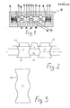
- FIG. 1 the so-called main stage 10 of a continuous directional valve with directional control in piston-slide construction is shown, which in its Movement sequence can be controlled by a pilot control, not shown.
- the main stage 10 has a housing 11 in which a piston 12 is movably arranged.
- the piston 12 is held in the rest position by two centering springs 13 supported on the housing 11, with chambers 15 for accommodating the centering springs 13 being formed in the housing 11 at the opposite ends of the piston 12.
- the chambers 15 have bores 14, which each establish a connection to the hydraulic pilot control, not shown.
- an axial guide bore 16 is formed for the control piston 12, which in this case has three circumferential recesses 17 arranged at a distance from one another, so that there are two piston collars 21 with the full piston cross section between them.
- the recesses 17 comprise an annular piston core 18, so that radially projecting control surfaces 19 result from the piston core 18, the outer edge of which, as a control edge 20, slides sealingly on the inner surface of the axial guide bore 16.
- the control edges 20 have triangular recesses 22, several of which are arranged at a distance from one another in the course of the control edge 20 surrounding the piston collar 21.
- the recesses 22 have a semi-conical shape in the direction of the piston core.
- the piston configuration 12 is surrounded by control chambers 23 which are formed in the housing 11 and surround the control piston 12 in an annular manner and which are connected to the outside via connection bores 27 to 30 of the valve and therefore not shown aggregates such as tank, pump, consumer are connected.
- the connection to the tank is denoted by 27, the connection to the pump by 28 and 29 and 30 each a connection to a consumer.
- webs 25 are arranged which cooperate with the control edges 20 of the piston 12 during its axial movement.
- two control chambers 23 are connected by a control channel 26, starting from the tank bore 27.
- FIG. 2 shows the design of the control piston according to the invention, in the form of a partial section of the control piston 12 with piston core 18, to which two piston collars 21 with two retracted control surfaces 19 are shown in sections on both sides.
- the recess 17 located between the control surfaces 19 has a connection to a housing-side control chamber 23 and to the connection bore 29.
- the control edges 20 of the piston collars 21 now run without a sudden change in direction in the manner of a sine curve tapering the width of the piston collar 21.
- control edge 20 has twice a sinusoidal vibration of half a period.
- any type of design of the course of the control edges must be regarded as belonging to the invention, which is a sudden one Avoids a change in direction of the course of the control edges with an abrupt increase in the flow forces, in particular also a straight line instead of a curved course of the control edges, as long as there is no linear section in between in the direction of the piston transverse axis.
- control surfaces 19 are arranged perpendicular to the piston core 18, so that the sine curve of the control edge 20 results in an opening cross section of the piston 12 up to its piston core 18.
- a further advantageous fine-tuning of the valve is possible in that the control surfaces are arranged obliquely towards the piston core, in such a way that a progressive release of the flow cross-section also results in the radial direction.
Landscapes
- Engineering & Computer Science (AREA)
- General Engineering & Computer Science (AREA)
- Mechanical Engineering (AREA)
- Sliding Valves (AREA)
- Valve Device For Special Equipments (AREA)
- Fluid-Damping Devices (AREA)
- Braking Arrangements (AREA)
- Fluid-Driven Valves (AREA)
Priority Applications (1)
| Application Number | Priority Date | Filing Date | Title |
|---|---|---|---|
| AT86105787T ATE57004T1 (de) | 1985-04-30 | 1986-04-26 | Hydraulisches steuerventil in kolben-schieberbauweise. |
Applications Claiming Priority (2)
| Application Number | Priority Date | Filing Date | Title |
|---|---|---|---|
| DE3515563 | 1985-04-30 | ||
| DE3515563A DE3515563C1 (de) | 1985-04-30 | 1985-04-30 | Hydraulisches Steuerventil in Kolben-Schieber-Bauweise |
Publications (3)
| Publication Number | Publication Date |
|---|---|
| EP0200182A2 true EP0200182A2 (fr) | 1986-11-05 |
| EP0200182A3 EP0200182A3 (en) | 1987-12-23 |
| EP0200182B1 EP0200182B1 (fr) | 1990-09-26 |
Family
ID=6269493
Family Applications (1)
| Application Number | Title | Priority Date | Filing Date |
|---|---|---|---|
| EP86105787A Expired - Lifetime EP0200182B1 (fr) | 1985-04-30 | 1986-04-26 | Vanne-pilote hydraulique du type robinet à piston |
Country Status (4)
| Country | Link |
|---|---|
| US (1) | US4739797A (fr) |
| EP (1) | EP0200182B1 (fr) |
| AT (1) | ATE57004T1 (fr) |
| DE (2) | DE3515563C1 (fr) |
Cited By (2)
| Publication number | Priority date | Publication date | Assignee | Title |
|---|---|---|---|---|
| WO2015032492A3 (fr) * | 2013-09-03 | 2015-07-30 | Hydac Technology Gmbh | Composants de soupape |
| EP4001669A1 (fr) * | 2020-11-16 | 2022-05-25 | Parker-Hannifin Corporation | Bobine de vanne proportionnelle avec gain de débit linéaire |
Families Citing this family (10)
| Publication number | Priority date | Publication date | Assignee | Title |
|---|---|---|---|---|
| JPH0743043B2 (ja) * | 1988-03-30 | 1995-05-15 | 株式会社ゼクセル | スプール弁 |
| JPH02129483A (ja) * | 1988-11-09 | 1990-05-17 | Aisin Aw Co Ltd | 圧力調整弁 |
| DE19847703B4 (de) * | 1998-10-16 | 2010-10-07 | Schaeffler Technologies Gmbh & Co. Kg | Mehrwegeventileinrichtung |
| DE19938884B4 (de) * | 1999-08-17 | 2009-10-01 | Schaeffler Kg | Wegeventil und Verfahren zur Optimierung von dessen Regelbarkeit und Bauaufwand |
| US6408882B1 (en) | 1999-11-08 | 2002-06-25 | Walter L. Smith, Jr. | Diverter valve |
| US8267121B2 (en) * | 2008-01-31 | 2012-09-18 | Caterpillar Inc. | Valve assembly for counteracting flow forces |
| US7707993B2 (en) * | 2008-06-24 | 2010-05-04 | Caterpillar Inc. | Electronic pressure relief in a mechanically actuated fuel injector |
| DE102008059434B3 (de) * | 2008-11-27 | 2010-01-07 | Parker Hannifin Gmbh & Co. Kg | Hydraulisches Kolbenschieberventil mit Stufenkolben |
| FR2960924B1 (fr) * | 2010-06-04 | 2013-04-05 | Messier Bugatti | Distributeur hydraulique. |
| CN101893011A (zh) * | 2010-07-30 | 2010-11-24 | 三一重工股份有限公司 | 液压阀、液压阀组及其控制方法 |
Family Cites Families (26)
| Publication number | Priority date | Publication date | Assignee | Title |
|---|---|---|---|---|
| GB190902195A (en) * | 1908-03-26 | 1909-07-22 | Adolph Schoencke | Improvements in Slide Valves suitable for Hydraulic Power Engines. |
| GB191210522A (en) * | 1912-05-03 | 1912-09-05 | James Andrews | Multiple Opening Balanced Slide Valves. |
| US1292013A (en) * | 1918-01-08 | 1919-01-21 | Continental Gin Co | Hydraulic-press valve mechanism. |
| FR990435A (fr) * | 1948-07-10 | 1951-09-21 | Karlstad Mekaniska Ab | Soupape |
| GB721904A (en) * | 1952-04-07 | 1955-01-12 | Jones & Shipman A A Ltd | Improvements in or relating to hydraulically-operated machine tools |
| US2702529A (en) * | 1952-04-23 | 1955-02-22 | Gen Motors Corp | Valve adapted for hydraulic power steering uses |
| US2953902A (en) * | 1956-08-31 | 1960-09-27 | Dover Corp | Hydraulic elevator control system |
| US2958340A (en) * | 1956-12-17 | 1960-11-01 | Banstrom Ind Inc | Spool valve |
| US3072149A (en) * | 1960-11-15 | 1963-01-08 | Clark Equipment Co | Detent for valve plungers |
| US3174510A (en) * | 1961-04-18 | 1965-03-23 | Gresen Mfg Company | Spool type control valve for controlling hydraulic actuators |
| GB1011751A (en) * | 1962-07-19 | 1965-12-01 | Zahnradfabrik Friedrichshafen | Improvements in or relating to hydraulic pressure control valves |
| FR1463559A (fr) * | 1965-01-27 | 1966-12-23 | Cam Gears Ltd | Distributeur à tiroir |
| US3323421A (en) * | 1965-05-21 | 1967-06-06 | Greenlee Bros & Co | Control for hydraulic actuator |
| US3463187A (en) * | 1968-02-07 | 1969-08-26 | Gen Signal Corp | Hydraulically operated power steering circuit |
| US3536291A (en) * | 1968-03-18 | 1970-10-27 | Allied Pacific Mfg Co | Spool valve |
| US3807454A (en) * | 1972-12-15 | 1974-04-30 | Gen Signal Corp | Low effort plunger |
| US3882883A (en) * | 1973-11-19 | 1975-05-13 | Fairmont Railway Motors Inc | Closed-open center hydraulic valve assembly |
| US3971216A (en) * | 1974-06-19 | 1976-07-27 | The Scott & Fetzer Company | Load responsive system with synthetic signal |
| US4008737A (en) * | 1974-08-26 | 1977-02-22 | The Bendix Corporation | Multi-path valve structure with means providing smooth flow patterns |
| DE2604208A1 (de) * | 1976-02-04 | 1977-08-11 | Friedrich Wilhelm I Friedrichs | Steuervorrichtung |
| US4089169A (en) * | 1976-08-19 | 1978-05-16 | The Scott & Fetzer Company | Pressure actuated signal fluid control for load responsive systems |
| DE2717384C2 (de) * | 1977-04-20 | 1983-12-22 | Mannesmann Rexroth GmbH, 8770 Lohr | Hydraulisch betätigtes Steuerventil |
| DE2904111C2 (de) * | 1979-02-03 | 1983-03-31 | Zahnradfabrik Friedrichshafen Ag, 7990 Friedrichshafen | Hydrostatische Lenkeinrichtung |
| DE3129594C2 (de) * | 1981-07-28 | 1985-01-17 | Messerschmitt-Bölkow-Blohm GmbH, 8000 München | Servosteuerventil |
| EP0076664A1 (fr) * | 1981-10-02 | 1983-04-13 | J.H. Fenner & Co. Limited | Perfectionnements dans ou concernant le contrôle de moteurs pneumatiques |
| DE3205860A1 (de) * | 1982-02-18 | 1983-08-25 | Mannesmann Rexroth GmbH, 8770 Lohr | Magnetbetaetigtes servoventil |
-
1985
- 1985-04-30 DE DE3515563A patent/DE3515563C1/de not_active Expired
-
1986
- 1986-04-26 EP EP86105787A patent/EP0200182B1/fr not_active Expired - Lifetime
- 1986-04-26 AT AT86105787T patent/ATE57004T1/de not_active IP Right Cessation
- 1986-04-26 DE DE8686105787T patent/DE3674452D1/de not_active Expired - Lifetime
- 1986-04-29 US US06/857,697 patent/US4739797A/en not_active Expired - Lifetime
Cited By (4)
| Publication number | Priority date | Publication date | Assignee | Title |
|---|---|---|---|---|
| WO2015032492A3 (fr) * | 2013-09-03 | 2015-07-30 | Hydac Technology Gmbh | Composants de soupape |
| US10167881B2 (en) | 2013-09-03 | 2019-01-01 | Hydac Technology Gmbh | Valve components |
| EP4001669A1 (fr) * | 2020-11-16 | 2022-05-25 | Parker-Hannifin Corporation | Bobine de vanne proportionnelle avec gain de débit linéaire |
| US11680649B2 (en) | 2020-11-16 | 2023-06-20 | Parker-Hannifin Corporstion | Proportional valve spool with linear flow gain |
Also Published As
| Publication number | Publication date |
|---|---|
| US4739797A (en) | 1988-04-26 |
| EP0200182B1 (fr) | 1990-09-26 |
| ATE57004T1 (de) | 1990-10-15 |
| EP0200182A3 (en) | 1987-12-23 |
| DE3515563C1 (de) | 1986-11-06 |
| DE3674452D1 (de) | 1990-10-31 |
Similar Documents
| Publication | Publication Date | Title |
|---|---|---|
| DE2950888C2 (fr) | ||
| DE1108028B (de) | Steuerschieber | |
| EP0688411B1 (fr) | Soupape de commande hydraulique | |
| EP0200182B1 (fr) | Vanne-pilote hydraulique du type robinet à piston | |
| DE2511991C2 (de) | Wegeventil mit elektromagnetischer Betätigungseinrichtung | |
| EP0581156B1 (fr) | Distributeur hydraulique type robinet à piston | |
| EP0174354B1 (fr) | Distributeur | |
| DE3905636A1 (de) | Schieberventil | |
| DE1947117B2 (de) | Verfahren zum herstellen eines ventilschiebers | |
| EP0049406B1 (fr) | Disposition et perfectionnement pour les passages de fluide dans des cylindres | |
| DE19514244A1 (de) | Hydraulische Zahnstangenlenkung | |
| AT390313B (de) | Kolbenschieberventil | |
| DE3226809A1 (de) | Hydraulisches wegeventil | |
| DE19651967A1 (de) | Wegeventil zur lastunabhängigen Steuerung eines hydraulischen Verbrauchers hinsichtlich Richtung und Geschwindigkeit | |
| DE2807542C2 (de) | Stromregelventil | |
| DE2602328C3 (de) | Drosselventil | |
| DE2212149A1 (de) | Steuerschieberventil für einen hydraulischen Servomotor | |
| DE1167139B (de) | Steuerschieber | |
| DE3004732C2 (fr) | ||
| EP1510699B1 (fr) | Procédé et dispositif pour commuter un flux | |
| DE2656855A1 (de) | Drosselschlitz | |
| EP0011145B1 (fr) | Patin pour machines à pistons hydrostatiques | |
| DE3132430C2 (de) | Arbeitszylinder für pneumatische oder hydraulische Arbeitsmedien | |
| EP1717451A2 (fr) | Vérin | |
| DE2151838C2 (de) | Hydraulische Steuerventileinrichtung |
Legal Events
| Date | Code | Title | Description |
|---|---|---|---|
| PUAI | Public reference made under article 153(3) epc to a published international application that has entered the european phase |
Free format text: ORIGINAL CODE: 0009012 |
|
| AK | Designated contracting states |
Kind code of ref document: A2 Designated state(s): AT BE CH DE FR GB IT LI LU NL SE |
|
| PUAL | Search report despatched |
Free format text: ORIGINAL CODE: 0009013 |
|
| AK | Designated contracting states |
Kind code of ref document: A3 Designated state(s): AT BE CH DE FR GB IT LI LU NL SE |
|
| 17P | Request for examination filed |
Effective date: 19880312 |
|
| 17Q | First examination report despatched |
Effective date: 19890120 |
|
| GRAA | (expected) grant |
Free format text: ORIGINAL CODE: 0009210 |
|
| AK | Designated contracting states |
Kind code of ref document: B1 Designated state(s): AT BE CH DE FR GB IT LI LU NL SE |
|
| PG25 | Lapsed in a contracting state [announced via postgrant information from national office to epo] |
Ref country code: SE Effective date: 19900926 Ref country code: NL Effective date: 19900926 Ref country code: BE Effective date: 19900926 |
|
| REF | Corresponds to: |
Ref document number: 57004 Country of ref document: AT Date of ref document: 19901015 Kind code of ref document: T |
|
| REF | Corresponds to: |
Ref document number: 3674452 Country of ref document: DE Date of ref document: 19901031 |
|
| ITF | It: translation for a ep patent filed | ||
| ET | Fr: translation filed | ||
| GBT | Gb: translation of ep patent filed (gb section 77(6)(a)/1977) | ||
| NLV1 | Nl: lapsed or annulled due to failure to fulfill the requirements of art. 29p and 29m of the patents act | ||
| PG25 | Lapsed in a contracting state [announced via postgrant information from national office to epo] |
Ref country code: AT Effective date: 19910426 |
|
| ITTA | It: last paid annual fee | ||
| PG25 | Lapsed in a contracting state [announced via postgrant information from national office to epo] |
Ref country code: LU Free format text: LAPSE BECAUSE OF NON-PAYMENT OF DUE FEES Effective date: 19910430 Ref country code: LI Effective date: 19910430 Ref country code: CH Effective date: 19910430 |
|
| PLBE | No opposition filed within time limit |
Free format text: ORIGINAL CODE: 0009261 |
|
| STAA | Information on the status of an ep patent application or granted ep patent |
Free format text: STATUS: NO OPPOSITION FILED WITHIN TIME LIMIT |
|
| 26N | No opposition filed | ||
| REG | Reference to a national code |
Ref country code: CH Ref legal event code: PL |
|
| PGFP | Annual fee paid to national office [announced via postgrant information from national office to epo] |
Ref country code: GB Payment date: 20010417 Year of fee payment: 16 Ref country code: FR Payment date: 20010417 Year of fee payment: 16 |
|
| PGFP | Annual fee paid to national office [announced via postgrant information from national office to epo] |
Ref country code: DE Payment date: 20010419 Year of fee payment: 16 |
|
| REG | Reference to a national code |
Ref country code: GB Ref legal event code: IF02 |
|
| PG25 | Lapsed in a contracting state [announced via postgrant information from national office to epo] |
Ref country code: GB Free format text: LAPSE BECAUSE OF NON-PAYMENT OF DUE FEES Effective date: 20020426 |
|
| PG25 | Lapsed in a contracting state [announced via postgrant information from national office to epo] |
Ref country code: DE Free format text: LAPSE BECAUSE OF NON-PAYMENT OF DUE FEES Effective date: 20021101 |
|
| GBPC | Gb: european patent ceased through non-payment of renewal fee |
Effective date: 20020426 |
|
| PG25 | Lapsed in a contracting state [announced via postgrant information from national office to epo] |
Ref country code: FR Free format text: LAPSE BECAUSE OF NON-PAYMENT OF DUE FEES Effective date: 20021231 |
|
| REG | Reference to a national code |
Ref country code: FR Ref legal event code: ST |
|
| PG25 | Lapsed in a contracting state [announced via postgrant information from national office to epo] |
Ref country code: IT Free format text: LAPSE BECAUSE OF NON-PAYMENT OF DUE FEES;WARNING: LAPSES OF ITALIAN PATENTS WITH EFFECTIVE DATE BEFORE 2007 MAY HAVE OCCURRED AT ANY TIME BEFORE 2007. THE CORRECT EFFECTIVE DATE MAY BE DIFFERENT FROM THE ONE RECORDED. Effective date: 20050426 |