EP0200201A2 - Porte-outil pour foreuses, dispositif de forage ainsi qu'un foret et un jeu de forets - Google Patents
Porte-outil pour foreuses, dispositif de forage ainsi qu'un foret et un jeu de forets Download PDFInfo
- Publication number
- EP0200201A2 EP0200201A2 EP86105890A EP86105890A EP0200201A2 EP 0200201 A2 EP0200201 A2 EP 0200201A2 EP 86105890 A EP86105890 A EP 86105890A EP 86105890 A EP86105890 A EP 86105890A EP 0200201 A2 EP0200201 A2 EP 0200201A2
- Authority
- EP
- European Patent Office
- Prior art keywords
- clamping
- drill
- tool holder
- jaw
- groove
- Prior art date
- Legal status (The legal status is an assumption and is not a legal conclusion. Google has not performed a legal analysis and makes no representation as to the accuracy of the status listed.)
- Withdrawn
Links
Images

Classifications
-
- B—PERFORMING OPERATIONS; TRANSPORTING
- B23—MACHINE TOOLS; METAL-WORKING NOT OTHERWISE PROVIDED FOR
- B23B—TURNING; BORING
- B23B31/00—Chucks; Expansion mandrels; Adaptations thereof for remote control
- B23B31/02—Chucks
- B23B31/10—Chucks characterised by the retaining or gripping devices or their immediate operating means
- B23B31/12—Chucks with simultaneously-acting jaws, whether or not also individually adjustable
- B23B31/1207—Chucks with simultaneously-acting jaws, whether or not also individually adjustable moving obliquely to the axis of the chuck in a plane containing this axis
- B23B31/1215—Details of the jaws
-
- B—PERFORMING OPERATIONS; TRANSPORTING
- B23—MACHINE TOOLS; METAL-WORKING NOT OTHERWISE PROVIDED FOR
- B23B—TURNING; BORING
- B23B31/00—Chucks; Expansion mandrels; Adaptations thereof for remote control
- B23B31/005—Cylindrical shanks of tools
-
- B—PERFORMING OPERATIONS; TRANSPORTING
- B23—MACHINE TOOLS; METAL-WORKING NOT OTHERWISE PROVIDED FOR
- B23B—TURNING; BORING
- B23B2231/00—Details of chucks, toolholder shanks or tool shanks
- B23B2231/02—Features of shanks of tools not relating to the operation performed by the tool
- B23B2231/0216—Overall cross sectional shape of the shank
- B23B2231/022—Triangular
- B23B2231/0224—Rounded triangular
-
- B—PERFORMING OPERATIONS; TRANSPORTING
- B23—MACHINE TOOLS; METAL-WORKING NOT OTHERWISE PROVIDED FOR
- B23B—TURNING; BORING
- B23B2231/00—Details of chucks, toolholder shanks or tool shanks
- B23B2231/02—Features of shanks of tools not relating to the operation performed by the tool
- B23B2231/026—Grooves
- B23B2231/0264—Axial grooves
-
- Y—GENERAL TAGGING OF NEW TECHNOLOGICAL DEVELOPMENTS; GENERAL TAGGING OF CROSS-SECTIONAL TECHNOLOGIES SPANNING OVER SEVERAL SECTIONS OF THE IPC; TECHNICAL SUBJECTS COVERED BY FORMER USPC CROSS-REFERENCE ART COLLECTIONS [XRACs] AND DIGESTS
- Y10—TECHNICAL SUBJECTS COVERED BY FORMER USPC
- Y10T—TECHNICAL SUBJECTS COVERED BY FORMER US CLASSIFICATION
- Y10T279/00—Chucks or sockets
- Y10T279/17—Socket type
- Y10T279/17042—Lost motion
-
- Y—GENERAL TAGGING OF NEW TECHNOLOGICAL DEVELOPMENTS; GENERAL TAGGING OF CROSS-SECTIONAL TECHNOLOGIES SPANNING OVER SEVERAL SECTIONS OF THE IPC; TECHNICAL SUBJECTS COVERED BY FORMER USPC CROSS-REFERENCE ART COLLECTIONS [XRACs] AND DIGESTS
- Y10—TECHNICAL SUBJECTS COVERED BY FORMER USPC
- Y10T—TECHNICAL SUBJECTS COVERED BY FORMER US CLASSIFICATION
- Y10T279/00—Chucks or sockets
- Y10T279/17—Socket type
- Y10T279/17615—Obliquely guided reciprocating jaws
-
- Y—GENERAL TAGGING OF NEW TECHNOLOGICAL DEVELOPMENTS; GENERAL TAGGING OF CROSS-SECTIONAL TECHNOLOGIES SPANNING OVER SEVERAL SECTIONS OF THE IPC; TECHNICAL SUBJECTS COVERED BY FORMER USPC CROSS-REFERENCE ART COLLECTIONS [XRACs] AND DIGESTS
- Y10—TECHNICAL SUBJECTS COVERED BY FORMER USPC
- Y10T—TECHNICAL SUBJECTS COVERED BY FORMER US CLASSIFICATION
- Y10T408/00—Cutting by use of rotating axially moving tool
- Y10T408/89—Tool or Tool with support
- Y10T408/907—Tool or Tool with support including detailed shank
-
- Y—GENERAL TAGGING OF NEW TECHNOLOGICAL DEVELOPMENTS; GENERAL TAGGING OF CROSS-SECTIONAL TECHNOLOGIES SPANNING OVER SEVERAL SECTIONS OF THE IPC; TECHNICAL SUBJECTS COVERED BY FORMER USPC CROSS-REFERENCE ART COLLECTIONS [XRACs] AND DIGESTS
- Y10—TECHNICAL SUBJECTS COVERED BY FORMER USPC
- Y10T—TECHNICAL SUBJECTS COVERED BY FORMER US CLASSIFICATION
- Y10T408/00—Cutting by use of rotating axially moving tool
- Y10T408/94—Tool-support
- Y10T408/95—Tool-support with tool-retaining means
- Y10T408/953—Clamping jaws
Definitions
- the invention relates to the field of drilling, in particular rock drilling, with the aid of drilling machines, in particular rotary hammers.
- drills with different diameters must be used, which can be clamped as far as possible in the same tool holder with their different clamping shafts.
- the problem arises that despite the different loading of the tool holder when drilling holes with different diameters, the Drills should always be carried along perfectly from the tool holder and faults should be avoided if possible.
- hammer drills there is the additional problem that the clamping shafts of the drills, when exerting the blows on the end face of the clamping shank in the tool holder without being pushed out, should be guided axially perfectly even with extremely thick or thin clamping shanks.
- a tool holder for rotary hammers which has at least two jaws for clamping different thickness clamping shafts of drills, for which a jaw carrier is provided, which is provided with a cavity for receiving the clamping shanks, in which at Clamping the clamping shafts, the jaws, which are mounted radially in and lockable in the jaw support, engage with their drivers.
- the invention is initially concerned with designing a tool holder of this type in such a way that it also solves the aforementioned problem for drills with thick drill shanks.
- the cavity of the jaw carrier is cylindrical and that when the tool holder for opening clamping shanks is opened to the maximum, the diameter of which corresponds to the diameter of the jaw carrier cavity, the radially inner parts of the drivers engage in this cavity.
- This outer circumference of tool holders for drilling machines should have a certain diameter, e.g. of 43 mm, do not exceed, e.g. the rotary hammers behind the chuck have a clamping neck that e.g. for fastening the front handle of the rotary hammer or for clamping in drill stands or for other attachments.
- the invention also consists in designing the tool holder for drilling machines mentioned at the outset in such a way that it also solves the problem mentioned at the outset for drills with thin and thinnest clamping shanks.
- This object is achieved according to the invention in that the driver of each jaw has an end face facing the cavity of the jaw carrier, which is interrupted by a rib extending axially to the cavity axis. This ensures that in drills with thicker clamping shafts the grooves can be formed for the engagement of the radially inner parts of the jaws and that in drills with thin clamping shafts the grooves are only provided for receiving the ribs.
- the small groove is sufficient for the engagement of the rib of the jaw, while the grooves for the engagement of the jaws can become ever deeper with increasing diameter of the clamping shank, so that not only the ribs, but especially the radially inner parts of the jaws themselves form drivers.
- the flanks of each jaw have an angle of 360 °: n, e.g. 120 °, if n is the number of jaws, e.g. three, unc is that the jaws can be adjusted and locked until the flanks touch each other. It is thereby achieved that when clamping the thinnest clamping shanks the jaws engaging the deepest in the cavity of the jaw holder lie against one another with their flanks, so that a further stabilization of the connection between the drill and the tool holder is achieved by this feature.
- the design of the tool holder according to the invention forms, together with a drill, a drilling device according to the invention if the clamping shaft of the drill has a smaller diameter than the diameter of the cavity of the jaw holder and each jaw of the jaw holder has an end face facing the cavity of the jaw holder and if there are contact surfaces for the clamping shaft planar contact of the end face of the jaws are formed by deformation of the originally cylindrical clamping shaft.
- each groove which receives the torque of the tool holder during drilling, lies in a radial plane of the clamping shank or is inclined relative to it about its radially outer boundary in a direction of rotation opposite to the direction of rotation of the drill. It is thereby achieved that no radial forces are exerted on the jaws by the transmission of the torque from the tool holder to the drill, through which the jaws could be pressed out of engagement with the grooves of the clamping shanks, particularly in the case of thicker clamping shanks.
- inventive features of the tool holders are combined in one tool holder, then such a tool holder results in an inventive set of drills with clamping shanks of different thicknesses, which is characterized in that the thicker clamping shafts have at least two axially extending grooves for the engagement of drivers of the Have tool holder and that the thinner clamping shafts with non-concentric to the axis of the clamping shafts provide contact surfaces are.
- This ensures that in the case of the thick clamping shafts, which are only insignificantly weakened by grooves, entrainment is achieved by the engagement of the jaws, this engagement being able to be adapted to the respective requirements by deepening the grooves in the case of thicker clamping shafts.
- the thin drills would not be suitable for hammer drills.
- suitable for rotary hammers in which the end faces of the jaws are interrupted by a rib extending axially to the cavity axis, the driving of the thinner drill bits can be achieved in that the grooves in the clamping shafts of these have approximately the same cross-section as the ribs of the jaws so that the ribs engage the grooves.
- a flat contact of the contact surfaces with the end faces of the jaws is no longer absolutely necessary, but is advantageous.
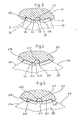
- the drill shown in Figure 1 for a hammer drill consists of a working shaft 11, which has the cutting edge, not shown in the drawing and a discharge groove 10, and a clamping shaft 12, the outer diameter of which is adapted to the outer diameter of the working shaft 11.
- the clamping shank has three straight, axially extending grooves 13 arranged at the same angular distance from one another.
- Each groove 13 is provided for the engagement of a rib 20 which projects radially from an end face 21 of a radially adjustable jaw 22 of a three-jaw chuck and extends axially (see FIG. 3).
- the grooves 13 extend only over part of the length of the clamping shaft 12, so that their rear ends are at a distance from the rear end face 14 of the clamping shaft 12.
- Each groove 13 is connected to the rear end face 14 by an insertion groove 15, the cross section of which is smaller than the cross section of the groove 13 but still so large that the radially inner part of the rib 20 can engage in the insertion groove.
- the clamping shaft can only be inserted axially into the chuck in such a position in which the insertion grooves 15 are aligned with the ribs 20 of the jaws 22. If the clamping shaft is then inserted so deeply into the chuck that the ribs 20 abut the front end of the grooves 13, then the ribs 20 are simultaneously aligned with the grooves 13, so that the ribs 20 engage properly in the grooves 13 by tightening the chuck and thereby centering the drill is guaranteed.
- FIG. 2 shows the thick clamping shank 112 of a drill which is provided for the same three-jaw chuck according to FIG. 3 as the drill according to FIG. 1.
- grooves 113 are provided in this groove, which are provided not only for receiving the rib 20, but also for receiving the radially inner part of the jaws 22, so that this part of the jaw carriers forms.
- a groove 117 is provided for the engagement of the rib 20, the cross section of which corresponds to the groove 13 of the exemplary embodiment according to FIG.
- the groove 113 is connected to the rear end face 114 of the clamping shaft by an insertion groove 115 which is exactly as long as the insertion groove 15.
- the groove 13 of the thin clamping shaft is considerably longer than the groove 113 of the thicker clamping shaft.
- the insertion groove 115 has approximately the same cross section as the rib 20 and thus as the groove 117.
- the insertion groove can also be larger here. It is merely essential that, in the the clamping shaft not yet been fixed exciting state it allows the insertion of the jaw, so that after the clamping of the clamping shank, the rear end of the grooves 113 forms a stop which an ejection of Boh - RERS prevented from the feed.
- the flank 24 of the jaw 22 which transmits the torque of the three-jaw chuck during drilling lies essentially in one at the largest opening of the three-jaw chuck Radial plane of the three-jaw chuck.
- the adjacent side wall 118 of the groove 113 has a corresponding inclination.
- the end face 21 of the jaw 22 is cylindrical. Their radius of curvature corresponds to the radius of curvature of the thickest clamping shaft 12, in which the groove 13 is provided only for the engagement of the rib 20. This ensures that the rib 20 can always fully engage in the groove 13 in the thinner drills.
- contact surfaces 416 and 516 are integrally formed on the clamping shafts 412 and 512.
- thinner clamping shafts when the torque is transmitted from the three-jaw chuck to the drill, a force which presses the jaws radially outwards is caused, which does not occur with the thickest clamping shaft 12. This has the advantage that this inevitable force, which presses the jaws radially outwards, is smaller in the thinner clamping shanks 412 and 512 and thus in the thinner drill bits and can be controlled more easily.
- FIG. 4 shows a modified embodiment of both the clamping shank 212 of a drill and the jaw 122 of a three-jaw chuck.
- the jaw 122 differs from the jaw 22 according to FIG. 3 in that the flanks 124 of each jaw 122 form an angle of 120 ° with one another and in that the three-jaw chuck is constructed in such a way that the jaws touch the flanks 124 against one another are adjustable and lockable. This ensures that with very thin clamping shanks, at which the jaws most engage in the interior of the cavity of a jaw holder, not shown in the drawing, the jaws clearly guide the clamped clamping shaft by this abutting. It should be noted here that clamping a chuck does not involve jamming, since the jaws only have to center the chuck shaft, but should enable it to move axially.
- the flanks 124 of the jaws and thus the side walls 218 of the groove 213 of all the clamping shafts 212, which are provided with grooves 213 for the engagement of the radially inner parts of the jaws 122, have an inclination , which generate a force pushing the jaws radially outwards.
- each jaw has 222 flanks 214 which are inclined at 120 ° to one another.
- the radially inner part of the jaws 222 which engages in the grooves 313 of the clamping shaft 312 and serves as a driver has flanks 214 ', of which the flank 214' which transmits the torque when driving the drill bit at the largest opening of the three-jaw chuck with respect to one of the inner ones Boundary line of the driver-containing radial plane of the cavity of the jaw carrier, not shown in the drawing, is inclined in a direction opposite to the direction of rotation of the three-jaw chuck.
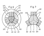
- FIGS. 6 and 7 show purely schematically how the torque from the three-jaw chuck to the clamping shank is shown by deformation of the clamping shank 412 and 512 of a drill while the end faces 321 of the jaws 322 of a three-jaw chuck which are mounted and lockable radially in a jaw carrier 325 remain the same can be transmitted without grooves being provided in the clamping shank.
- a particularly advantageous embodiment can be provided for the thickest clamping shanks.
- the jaws 22, 122, 222, 322 are guided in a jaw holder 325, which is only indicated schematically in FIG.
- the bore 326 is cylindrical and that the jaws are pulled completely out of the cavity at the largest opening of the three-jaw chuck, so that a clamping shank is inserted into the cavity can be guided, the diameter of which corresponds to the inner diameter of the cavity in such a way that it is guided axially through this inner cavity.
- the jaws are then inserted into the grooves.
- the insertion grooves provided on the clamping shaft then make it possible to insert the clamping shaft into the three-jaw chuck despite its guidance through the wall and despite the jaws 322 engaging in the cavity 326, thanks to the insertion grooves.
- the two side walls 118, 218 and 318 of the grooves 113 and 213 and 313 form the same angle with one another. So that the jaws of the drills of different thickness always engage in these grooves with as little play as possible, the exemplary embodiments provide that the distances between the radially inner boundaries of the side walls mentioned are the same for all these drills.
- a manually operable adjusting member is provided for fixing the jaws 22, 122, 322 to a desired diameter.
- 325 markie on the jaw holder Stations for such positions of the adjusting member, not shown in the drawing are present, in which the drivers of the jaws engage radially so deeply in the cavity 326 of the jaw holder 325 that the desired clamping shaft 12, 112, 212 and 312 only in one position in the chuck 1, the rib 20 serving as a driver or, in the case of the drills with thicker clamping shafts, the driver formed by the radially inner part of the jaws 22, 122, 222 engages in the insertion groove 15, 115 for the drill according to FIG.
- the flank 24 of the jaw 22 transmitting the torque of the three-jaw chuck lies essentially in a radial plane of the three-jaw chuck when the three-jaw chuck is largest.
- This feature is not mandatory, since when the drill is driven, the load between the side wall 118 and the flank 24 (the groove 113 or the jaw 22) causes a friction force which prevents the jaw 22 from being pressed out even in the event of an unfavorable inclination can.
- flank 24 which transmits the torque of the tool holder to the drill, is inclined at the various openings of the tool holder relative to the immediately adjacent radial plane of the jaw carrier cavity 326 (FIG. 6) in such a way that any that occur radially on the jaws radial forces acting outwards are at most as great as the frictional forces between the flanks 24 of the jaws and the side walls 118 of the grooves 113.
Landscapes
- Engineering & Computer Science (AREA)
- Mechanical Engineering (AREA)
- Gripping On Spindles (AREA)
- Drilling Tools (AREA)
Applications Claiming Priority (2)
| Application Number | Priority Date | Filing Date | Title |
|---|---|---|---|
| DE19853515555 DE3515555A1 (de) | 1985-04-30 | 1985-04-30 | Werkzeugaufnahme fuer bohrmaschinen, bohrvorrichtung sowie bohrer und bohrersatz |
| DE3515555 | 1985-04-30 |
Publications (2)
| Publication Number | Publication Date |
|---|---|
| EP0200201A2 true EP0200201A2 (fr) | 1986-11-05 |
| EP0200201A3 EP0200201A3 (fr) | 1988-07-20 |
Family
ID=6269486
Family Applications (1)
| Application Number | Title | Priority Date | Filing Date |
|---|---|---|---|
| EP86105890A Withdrawn EP0200201A3 (fr) | 1985-04-30 | 1986-04-29 | Porte-outil pour foreuses, dispositif de forage ainsi qu'un foret et un jeu de forets |
Country Status (3)
| Country | Link |
|---|---|
| US (1) | US4702651A (fr) |
| EP (1) | EP0200201A3 (fr) |
| DE (1) | DE3515555A1 (fr) |
Cited By (3)
| Publication number | Priority date | Publication date | Assignee | Title |
|---|---|---|---|---|
| EP1340570A1 (fr) * | 2002-02-27 | 2003-09-03 | Reiner Quanz | Outil de coupe rotatif avec une queue de serrage |
| FR2876048A1 (fr) * | 2004-10-06 | 2006-04-07 | Yves Georges Pailler | Dispositif pour fixer les forets avec des pinces ou des mandrins |
| CN104863566A (zh) * | 2015-05-20 | 2015-08-26 | 山河智能装备股份有限公司 | 一种多功能钻具控制装置 |
Families Citing this family (13)
| Publication number | Priority date | Publication date | Assignee | Title |
|---|---|---|---|---|
| DE3413432A1 (de) * | 1983-12-27 | 1985-07-04 | Gebrüder Heller GmbH Werkzeugfabrik, 2807 Achim | Bohrer fuer handbohrmaschinen |
| DE3817644A1 (de) * | 1988-05-25 | 1989-11-30 | Hilti Ag | Werkzeug mit laengsnuten am einsteckende |
| FR2635039B1 (fr) * | 1988-08-05 | 1990-11-02 | Prospection & Inventions | Foret comprenant une queue avec des rainures |
| DE4242452A1 (de) * | 1992-07-15 | 1994-01-20 | Hilti Ag | Werkzeug und Werkzeugaufnahme für Handwerkzeuggeräte |
| USD394865S (en) | 1995-11-09 | 1998-06-02 | Ronan John S | Tube driver for hex shank drill bit |
| DE69938838D1 (de) * | 1998-11-12 | 2008-07-10 | Black & Decker Inc | Futter, bohrer, zusammenbau dafür und montagemethode |
| EP1769868B1 (fr) * | 1998-11-12 | 2012-08-01 | Black & Decker, Inc. | Mandrin et procédé d'assemblage de ce dernier |
| EP1218135A4 (fr) * | 1999-07-21 | 2004-12-15 | Black & Decker Inc | Mandrin a entrainement mecanique |
| GB2393931A (en) * | 2002-10-10 | 2004-04-14 | Black & Decker Inc | Tool for a rotary hammer |
| USD570663S1 (en) * | 2006-06-02 | 2008-06-10 | C4 Carbides Limited | Hard tile drill bit |
| US8403339B2 (en) | 2008-06-18 | 2013-03-26 | Jacobs Chuck Manufacturing Company | Self tightening chuck with an axial lock |
| US8376371B2 (en) * | 2008-09-17 | 2013-02-19 | Jacobs Chuck Manufacturing Company | Locking chuck jaws |
| JP5492177B2 (ja) * | 2011-12-02 | 2014-05-14 | 本田技研工業株式会社 | 切削方法 |
Family Cites Families (10)
| Publication number | Priority date | Publication date | Assignee | Title |
|---|---|---|---|---|
| GB561478A (en) * | 1942-11-17 | 1944-05-22 | Frederic Alexander Lanfranconi | Improvements in the manufacture of taps, reamers and the like |
| DE3118691A1 (de) * | 1981-05-12 | 1982-12-02 | Gebrüder Heller GmbH Werkzeugfabrik, 2807 Achim | Mehrbackenfutter und werkzeug sowie bohrersatz fuer das mehrbackenfutter und verfahren zum spanlosen formen mindestens eines teiles des werkzeuges |
| DK333581A (da) * | 1981-07-24 | 1983-01-25 | Duforac Kartro A S | Vaerktoejsskaft isaer til slag eller hammerbor |
| DE3132449C2 (de) * | 1981-08-17 | 1994-10-27 | Hilti Ag | Werkzeughalter für Bohrhämmer |
| CH656816A5 (de) * | 1981-11-11 | 1986-07-31 | Hilti Ag | Bohrer fuer handgeraete. |
| DE3310147A1 (de) * | 1983-03-21 | 1984-09-27 | Hilti Ag, Schaan | Bohrfutter fuer schlagbohrbetrieb |
| DE3310146C2 (de) * | 1983-03-21 | 1985-08-14 | Hilti Ag, Schaan | Bohrfutter für Schlagbohrbetrieb |
| DE3413432A1 (de) * | 1983-12-27 | 1985-07-04 | Gebrüder Heller GmbH Werkzeugfabrik, 2807 Achim | Bohrer fuer handbohrmaschinen |
| DE3413005C2 (de) * | 1984-04-06 | 1986-04-17 | Röhm GmbH, 7927 Sontheim | Werkzeugschaft mit mehreren axial verlaufenden Nuten |
| DE3429419A1 (de) * | 1984-08-09 | 1986-02-20 | Hilti Ag, Schaan | Bohrwerkzeug fuer handbohrmaschinen |
-
1985
- 1985-04-30 DE DE19853515555 patent/DE3515555A1/de not_active Withdrawn
-
1986
- 1986-04-28 US US06/856,181 patent/US4702651A/en not_active Expired - Fee Related
- 1986-04-29 EP EP86105890A patent/EP0200201A3/fr not_active Withdrawn
Cited By (4)
| Publication number | Priority date | Publication date | Assignee | Title |
|---|---|---|---|---|
| EP1340570A1 (fr) * | 2002-02-27 | 2003-09-03 | Reiner Quanz | Outil de coupe rotatif avec une queue de serrage |
| FR2876048A1 (fr) * | 2004-10-06 | 2006-04-07 | Yves Georges Pailler | Dispositif pour fixer les forets avec des pinces ou des mandrins |
| CN104863566A (zh) * | 2015-05-20 | 2015-08-26 | 山河智能装备股份有限公司 | 一种多功能钻具控制装置 |
| CN104863566B (zh) * | 2015-05-20 | 2017-09-29 | 山河智能装备股份有限公司 | 一种多功能钻具控制装置 |
Also Published As
| Publication number | Publication date |
|---|---|
| US4702651A (en) | 1987-10-27 |
| DE3515555A1 (de) | 1986-11-06 |
| EP0200201A3 (fr) | 1988-07-20 |
Similar Documents
| Publication | Publication Date | Title |
|---|---|---|
| DE3716915C2 (fr) | ||
| DE3008394C2 (de) | Kombiniertes Bohr- und Schraubwerkzeug | |
| EP2274125B1 (fr) | Outil de tournage, notamment outil de forage | |
| DE2650134C2 (fr) | ||
| EP0200201A2 (fr) | Porte-outil pour foreuses, dispositif de forage ainsi qu'un foret et un jeu de forets | |
| EP0456003B1 (fr) | Perceuse manuelle | |
| EP0553124B1 (fr) | Dispositif pour machines-outils manuelles | |
| DE2624370B2 (de) | Scheibenschneider für Blech o.dgl | |
| CH618113A5 (fr) | ||
| EP0732164B1 (fr) | Outil de perçage, en particulier pour le perçage par percussion de la pierre | |
| DE3429419A1 (de) | Bohrwerkzeug fuer handbohrmaschinen | |
| DE3310147C2 (fr) | ||
| EP0147830A2 (fr) | Foret pour perceuses tenues à la main | |
| DE3041650C2 (de) | Rollkupplungsfutter | |
| EP0141903B1 (fr) | Perceuse à percussion | |
| DE2056091C3 (de) | Spitzbohrwerkzeug | |
| CH671719A5 (fr) | ||
| EP0175065B1 (fr) | Mandrin réglable | |
| DE3118691C2 (fr) | ||
| DE3540223C2 (fr) | ||
| DE3413005C2 (de) | Werkzeugschaft mit mehreren axial verlaufenden Nuten | |
| DE3443138C2 (fr) | ||
| DE202005015451U1 (de) | Kombinationswerkzeug | |
| EP0491153B1 (fr) | Porte-outil pour un fôret | |
| DE4032739A1 (de) | Werkzeug |
Legal Events
| Date | Code | Title | Description |
|---|---|---|---|
| PUAI | Public reference made under article 153(3) epc to a published international application that has entered the european phase |
Free format text: ORIGINAL CODE: 0009012 |
|
| AK | Designated contracting states |
Kind code of ref document: A2 Designated state(s): CH DE FR GB IT LI |
|
| PUAL | Search report despatched |
Free format text: ORIGINAL CODE: 0009013 |
|
| AK | Designated contracting states |
Kind code of ref document: A3 Designated state(s): CH DE FR GB IT LI |
|
| 17P | Request for examination filed |
Effective date: 19890105 |
|
| 17Q | First examination report despatched |
Effective date: 19900214 |
|
| STAA | Information on the status of an ep patent application or granted ep patent |
Free format text: STATUS: THE APPLICATION IS DEEMED TO BE WITHDRAWN |
|
| 18D | Application deemed to be withdrawn |
Effective date: 19910319 |
|
| RIN1 | Information on inventor provided before grant (corrected) |
Inventor name: KLEINE, WERNER, DIPL.-ING., DIPL.-WIRTSCH |