EP0200256B1 - Procédé et appareil de revêtement d'une fibre - Google Patents
Procédé et appareil de revêtement d'une fibre Download PDFInfo
- Publication number
- EP0200256B1 EP0200256B1 EP86200631A EP86200631A EP0200256B1 EP 0200256 B1 EP0200256 B1 EP 0200256B1 EP 86200631 A EP86200631 A EP 86200631A EP 86200631 A EP86200631 A EP 86200631A EP 0200256 B1 EP0200256 B1 EP 0200256B1
- Authority
- EP
- European Patent Office
- Prior art keywords
- opening
- coating
- coating material
- pressure chamber
- fiber
- Prior art date
- Legal status (The legal status is an assumption and is not a legal conclusion. Google has not performed a legal analysis and makes no representation as to the accuracy of the status listed.)
- Expired
Links
- 238000000576 coating method Methods 0.000 title claims abstract description 136
- 239000011248 coating agent Substances 0.000 title claims abstract description 135
- 239000000835 fiber Substances 0.000 title claims abstract description 96
- 238000000034 method Methods 0.000 title claims abstract description 34
- 239000000463 material Substances 0.000 claims abstract description 68
- 230000005499 meniscus Effects 0.000 claims abstract description 12
- 239000007788 liquid Substances 0.000 claims abstract description 9
- -1 polytetrafluoroethylene Polymers 0.000 claims description 5
- 229920001343 polytetrafluoroethylene Polymers 0.000 claims description 5
- 239000004810 polytetrafluoroethylene Substances 0.000 claims description 5
- 229910052724 xenon Inorganic materials 0.000 claims description 5
- FHNFHKCVQCLJFQ-UHFFFAOYSA-N xenon atom Chemical compound [Xe] FHNFHKCVQCLJFQ-UHFFFAOYSA-N 0.000 claims description 5
- 239000004338 Dichlorodifluoromethane Substances 0.000 claims description 2
- 238000004891 communication Methods 0.000 claims description 2
- PXBRQCKWGAHEHS-UHFFFAOYSA-N dichlorodifluoromethane Chemical compound FC(F)(Cl)Cl PXBRQCKWGAHEHS-UHFFFAOYSA-N 0.000 claims description 2
- 235000019404 dichlorodifluoromethane Nutrition 0.000 claims description 2
- 239000011247 coating layer Substances 0.000 claims 1
- 239000013307 optical fiber Substances 0.000 abstract description 7
- 238000011010 flushing procedure Methods 0.000 abstract description 2
- 239000007789 gas Substances 0.000 description 33
- 239000010410 layer Substances 0.000 description 10
- 238000001723 curing Methods 0.000 description 8
- 238000012360 testing method Methods 0.000 description 8
- XLYOFNOQVPJJNP-UHFFFAOYSA-N water Substances O XLYOFNOQVPJJNP-UHFFFAOYSA-N 0.000 description 7
- 239000004033 plastic Substances 0.000 description 6
- 238000001816 cooling Methods 0.000 description 5
- 230000015572 biosynthetic process Effects 0.000 description 4
- 238000010438 heat treatment Methods 0.000 description 4
- 230000001105 regulatory effect Effects 0.000 description 4
- 238000003860 storage Methods 0.000 description 4
- 238000003848 UV Light-Curing Methods 0.000 description 3
- 208000002352 blister Diseases 0.000 description 3
- 238000002474 experimental method Methods 0.000 description 3
- 239000003365 glass fiber Substances 0.000 description 3
- 230000003287 optical effect Effects 0.000 description 3
- 239000011241 protective layer Substances 0.000 description 3
- 238000004804 winding Methods 0.000 description 3
- NIXOWILDQLNWCW-UHFFFAOYSA-M Acrylate Chemical compound [O-]C(=O)C=C NIXOWILDQLNWCW-UHFFFAOYSA-M 0.000 description 2
- RYGMFSIKBFXOCR-UHFFFAOYSA-N Copper Chemical compound [Cu] RYGMFSIKBFXOCR-UHFFFAOYSA-N 0.000 description 2
- 230000004888 barrier function Effects 0.000 description 2
- 229910052802 copper Inorganic materials 0.000 description 2
- 239000010949 copper Substances 0.000 description 2
- UMNKXPULIDJLSU-UHFFFAOYSA-N dichlorofluoromethane Chemical compound FC(Cl)Cl UMNKXPULIDJLSU-UHFFFAOYSA-N 0.000 description 2
- 229940099364 dichlorofluoromethane Drugs 0.000 description 2
- 230000000694 effects Effects 0.000 description 2
- 239000006260 foam Substances 0.000 description 2
- 239000011521 glass Substances 0.000 description 2
- 238000010926 purge Methods 0.000 description 2
- 230000008719 thickening Effects 0.000 description 2
- 230000005540 biological transmission Effects 0.000 description 1
- 230000005587 bubbling Effects 0.000 description 1
- 238000010276 construction Methods 0.000 description 1
- 230000003247 decreasing effect Effects 0.000 description 1
- 238000007872 degassing Methods 0.000 description 1
- 238000010586 diagram Methods 0.000 description 1
- 239000000428 dust Substances 0.000 description 1
- 239000012943 hotmelt Substances 0.000 description 1
- 238000009413 insulation Methods 0.000 description 1
- 239000004922 lacquer Substances 0.000 description 1
- 230000007774 longterm Effects 0.000 description 1
- 238000004519 manufacturing process Methods 0.000 description 1
- 239000002184 metal Substances 0.000 description 1
- 229910052751 metal Inorganic materials 0.000 description 1
- 239000000203 mixture Substances 0.000 description 1
- 239000005304 optical glass Substances 0.000 description 1
- 239000002245 particle Substances 0.000 description 1
- 230000035515 penetration Effects 0.000 description 1
- 239000006223 plastic coating Substances 0.000 description 1
- 229920000642 polymer Polymers 0.000 description 1
- 229920002379 silicone rubber Polymers 0.000 description 1
- 239000004945 silicone rubber Substances 0.000 description 1
- 239000007779 soft material Substances 0.000 description 1
- 229910001220 stainless steel Inorganic materials 0.000 description 1
- 239000010935 stainless steel Substances 0.000 description 1
Images

Classifications
-
- H—ELECTRICITY
- H01—ELECTRIC ELEMENTS
- H01B—CABLES; CONDUCTORS; INSULATORS; SELECTION OF MATERIALS FOR THEIR CONDUCTIVE, INSULATING OR DIELECTRIC PROPERTIES
- H01B13/00—Apparatus or processes specially adapted for manufacturing conductors or cables
- H01B13/06—Insulating conductors or cables
- H01B13/14—Insulating conductors or cables by extrusion
-
- B—PERFORMING OPERATIONS; TRANSPORTING
- B05—SPRAYING OR ATOMISING IN GENERAL; APPLYING FLUENT MATERIALS TO SURFACES, IN GENERAL
- B05C—APPARATUS FOR APPLYING FLUENT MATERIALS TO SURFACES, IN GENERAL
- B05C3/00—Apparatus in which the work is brought into contact with a bulk quantity of liquid or other fluent material
- B05C3/02—Apparatus in which the work is brought into contact with a bulk quantity of liquid or other fluent material the work being immersed in the liquid or other fluent material
- B05C3/12—Apparatus in which the work is brought into contact with a bulk quantity of liquid or other fluent material the work being immersed in the liquid or other fluent material for treating work of indefinite length
-
- C—CHEMISTRY; METALLURGY
- C03—GLASS; MINERAL OR SLAG WOOL
- C03C—CHEMICAL COMPOSITION OF GLASSES, GLAZES OR VITREOUS ENAMELS; SURFACE TREATMENT OF GLASS; SURFACE TREATMENT OF FIBRES OR FILAMENTS MADE FROM GLASS, MINERALS OR SLAGS; JOINING GLASS TO GLASS OR OTHER MATERIALS
- C03C25/00—Surface treatment of fibres or filaments made from glass, minerals or slags
- C03C25/10—Coating
- C03C25/12—General methods of coating; Devices therefor
- C03C25/18—Extrusion
Definitions
- the invention relates to a method for coating a fiber, wherein a fiber to be coated is passed through a feed channel having a constricted inlet opening, passed through a pressure chamber filled with liquid coating material and drawn through the outflow opening of a nozzle, the coating material of the pressure chamber being under pressure is fed.
- the invention also relates to an apparatus for performing the method.
- Fibers are often coated to protect them from mechanical damage, insulation, coding, etc.
- glass fibers that are used for optical communication are to be covered with a protective layer immediately after production, after being drawn from a crucible or from a preform. Because glass is a brittle material, the strength and mechanical reliability of the fiber depend heavily on the quality of the surface of the fiber in the long term. Scratches, hairline cracks and dust particles on the surface of the fiber are not allowed.
- the temperature and gas conditions in the drawing furnace or in the crucible should be carefully selected. In order to maintain this perfect surface of the fiber once it has been obtained, the fiber must be covered with a protective layer.
- the coating material usually a polymer plastic
- the coating is applied in liquid form and then thermally cured by UV light.
- the coating can consist of a single plastic layer or of two protective layers; in the case of a double coating, two plastic layers or a first layer made of a relatively soft material, such as silicone rubber or a "hot melt” wax, and a second layer made of plastic can be applied. It is common to apply a coating with a thickness of approx. 25 to 60 ⁇ m on a commonly used standard glass fiber with a diameter of 125 ⁇ m.
- a glass fiber is provided with a coating by passing the fiber through a container with liquid coating material and then pulling it through the outflow opening of a nozzle.
- Slip the risk arises of through sliding or slipping (. Slip "), ie, the fiber exits the outflow opening entirely without coating or with gaps in the coating. By slipping or sliding occurs when the thrust forces one on the interface between the coating material and fiber exceed critical value.
- the concentration of bubbles is inadmissibly high.
- the bubbles arise from the fact that z. B. when using the method with an open vessel, the fiber pulls a deep funnel or cone when entering the liquid coating material, which is located in the open vessel. A relatively large amount of air is torn into the coating material by the fiber traveling at high speed. Through circulation, vibrations, etc. Air pockets occur in the coating material. Some of these air pockets are enclosed in the coating in the form of bubbles.
- the pulling speed is the speed at which the fiber is drawn and passed through the vessel. Most of the bubbles accumulate on the surface of the coating material and form a thick layer of foam.
- Bubbles in the coating of optical fibers are extremely undesirable: a first disadvantageous effect is that the fiber comes to lie eccentrically in the outflow opening of the nozzle and does not follow the center line of the outflow opening; the fiber is not coaxial with the coating; Air bubbles can also cause variations in the diameter and thickness of the coating; Larger air bubbles can extend through almost the entire thickness of the coating, so that the fiber is not covered locally. In general, air bubbles in the coating affect the mechanical and optical properties of the fiber.
- a fiber to be covered with a coating is copper winding wire.
- the winding wire used in practice usually has a diameter between 20 ⁇ m and 1250 pm.
- This wire is covered with an electrically insulating layer, which consists of a lacquer layer with a thickness from 4 ⁇ m for a wire with a diameter of 20 ⁇ m to a thickness of 60 pm for a wire with a diameter of 1250 ⁇ m. Because of the relatively small thickness of the coating, a bubble-free coating is absolutely necessary for this type of fiber.
- the invention has for its object to provide a method in which the entrainment of air and the inclusion of bubbles is largely reduced right from the start and with which it is possible to use fibers with lower concentrations of bubbles and even bubble-free, ie without microscopic at one Enlargement of 200 perceptible bubbles to be coated, even at very high drawing speeds that have not yet been used.
- this is essentially achieved in that the coating material is supplied at such a pressure and in such an amount that it rises to a certain height in the supply channel and forms a convex meniscus.
- the fiber is fed to the pressure chamber from the constricted inlet opening via a guide channel.
- the narrowed inlet opening on the outlet side opens directly into a pressure chamber and connects to a feed channel on the inlet side; a substantial abrupt pressure build-up occurs only in the constricted inlet opening; Air bubbles can freely enter the feed channel.
- a further preferred embodiment of the method according to the invention is characterized in that the temperature of the coating material present in the pressure chamber is set in such a way that a coating with the desired thickness is obtained.
- the thickness of the coating is primarily determined by the dimensions of the outflow opening in the nozzle and is influenced by the viscosity of the coating material in the pressure chamber. If the desired thickness of the coating deviates, the temperature and thereby the viscosity of the coating material in the pressure chamber are readjusted in such a way that the desired thickness is maintained.
- the drawing speed at which a fiber can still be coated absolutely free of bubbles can be increased still further, for example by a factor of 4, up to values previously thought impossible.
- dichlorofluoromethane is used for this purpose.
- a bubble-free coating was applied to the fiber even at drawing speeds of 12 m / s.
- the said Gas has a kinematic viscosity of 2.3. 10- 6 m 2 / s, which is 6.4 times lower than that of air.
- Dichlorofluoromethane is available in large quantities and is relatively inexpensive, in any case cheaper than xenon.
- the pulling speed may possibly be increased even further. In tests, the maximum drawing speed was limited to 12 m / s because the drawing system available for the tests did not allow a higher drawing speed.
- a fiber with a coating applied by the method according to the invention is absolutely bubble-free, i.e. that the coating contains no microscopic bubbles, in any case no bubbles with a diameter larger than 1 to 2 ⁇ m.
- a bubble-free coating is particularly important for optical glass fibers and for copper winding wire.
- the invention can be applied in an equally advantageous manner for coating fibers with a different composition, e.g. B. plastic fibers, metal fibers in general and many more
- the invention also relates to a device for carrying out the method with a housing with a pressure chamber, a nozzle with an outflow opening, a shut-off part with a feed channel having a constricted inlet opening, which shuts off the pressure chamber on the top, a feed opening in the wall of the housing Supplying liquid coating material and an overflow opening in the side wall of the housing; according to the invention, this device is characterized in that the overflow opening is made in the side wall of the housing at a height which is lower than the level of the constricted entry opening.
- the device according to the invention forms a closed coating vessel with supply of the coating material under pressure.
- the constricted supply channel with the entrance opening can be installed directly in the barrier wall. If, however, the feed channel has a guide channel for guiding a fiber to be coated, the guide channel forms a connection between the constricted inlet opening and the pressure chamber, in other words, in a preferred embodiment of the device according to the invention. the constricted inlet opening is located at the free end of the guide channel facing away from the pressure chamber.
- Another preferred embodiment of the device according to the invention is characterized by a tubular element which has the feed channel with the constricted input opening and the guide channel and which is fastened interchangeably to the shut-off part.
- the device can be easily adapted and changed for coating fibers with different diameters by replacing the nozzle and by replacing the tubular element with an element whose constricted inlet opening and / or guide channel has different dimensions.
- the tubular element is made of polytetrafluoroethylene. Said plastic is not wetted by most liquids, among which the coating material, whereby the formation of a convex meniscus of the coating material in the feed channel or in its inlet opening is facilitated.
- the drawing speed at which it is still possible to coat a fiber without the formation of bubbles, can be substantially increased by flushing the area around the inlet opening with a gas whose kinematic viscosity is lower than that of air.
- a further preferred embodiment of the device according to the invention is characterized in that the housing is closed by a cover with a central through opening and is provided with a supply opening for supplying a gas to the space of the housing lying between the shut-off part and the cover.
- the housing has a circulation chamber which surrounds the part of the pressure chamber which faces the outflow opening.
- the invention is explained in more detail using an exemplary embodiment for coating an optical fiber.
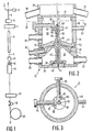
- a drawing furnace 5 To serves the system 1 known per se in FIG. 1 with a holder 3 for a preform P, a drawing furnace 5, a measuring device 7 for measuring the fiber diameter, a cooling device 9, a coating device 11 for applying a coating, a testing device 13 for checking the concentric position of the fiber and the coating, a curing device 15, a measuring device 17 for measuring the diameter of the coated fiber, a tensiometer 19 for measuring the pulling force, and a pulling device, which is designed as a take-up reel 21 in the exemplary embodiment shown.
- a curing device working with UV light is used for the often used.
- the drawing furnace 5, the measuring devices 7 and 17, the cooling device 9, the testing device 13 and the curing device 15 can be of a construction known per se and do not form part of the present invention.
- This system 1 is operated in a manner known per se as follows.
- a fiber F is drawn from a preform P by heating in the drawing furnace 5, the drawing speed being regulated by means of the diameter measuring device 7 such that the diameter of the fiber F is as constant as possible.
- the fiber F is cooled in the cooling device 9 to a temperature at which a plastic coating can be applied.
- the fiber is coated in the coating device 11.
- the fiber F is passed through the curing device 15 for curing the coating.
- the diameter of the coated fiber is measured in the diameter measuring device 17 and the tensile force is measured in the tensiometer 19.
- the finished fiber is wound onto the reel 21, which ensures the further transport of the fiber F through the system 1.
- the device 11 is of the so-called closed type with supply of the coating material under pressure and, for this purpose, has a housing 31 with a circulation chamber 33, a bottom part 35 and a shut-off part 37.
- a nozzle 40 is exchangeably attached by means of a screw connection 39, which nozzle is provided with an outflow opening 41 which adjoins an outflow channel 43.
- the connections 45 and 47 serve for the circulation of warm water through the circulation chamber 33.
- the shut-off part 37 has a cylindrical wall part 49 and a wall part 51 extending in the transverse direction, which enclose a space 50 and is connected to the housing by means of a screw connection 53 31 attached.
- a tubular element 55 is exchangeably fastened centrally in the wall part 51, this element having a feed channel 56 with a constricted input opening 57 and a guide channel 59 and an end face 60.
- the transverse wall 51 closes off a chamber 61 which serves as a pressure chamber.
- a connection 63 is used to supply coating material C under pressure to the chamber 61.
- An outflow opening 65 acts as an overflow and serves to discharge any coating material that flows over.
- a further supply opening 67 for supplying a gas is provided in the wall part 49.
- a cover 69 with a shut-off wall 71 with a central passage opening 73 and with connections 75 serves for the forced removal of gas by means of a suction system, which is still not shown.
- the tubular element 55 and the shut-off wall 71 are made of stainless steel. The parts that come into contact with the coating material are polished and have no sharp edges or dead corners.
- the tubular element 55 is elastically deformable and is preferably made of polytetrafluoroethylene.
- An adjustment block 77 is fastened on the tubular element 55 at the level of the inlet opening 57.
- In the cylindrical wall 49 there are two adjusting screws 79 standing perpendicular to each other, which are provided with disks or wheels 81 which cooperate with straight guide grooves 83 in the adjusting block 77.
- the barrier wall 7 is made of glass so that observation with the naked eye is possible.
- Fig. 4 shows schematically in addition to the coating device 11, the necessary elements for supplying the coating material and the gas and for the circulation of water in the circulation chamber 33.
- 85 denotes a storage vessel in which a certain amount of coating material under pressure and at a certain Temperature is stored.
- 87 designates a pressure control device.
- the coating material is brought to a certain temperature by means of warm water, the supply of the water being regulated by means of a thermostat 89. When the coating material is heated, degassing takes place at the same time, so that all air bubbles disappear from it.
- Another thermostat is represented by 91, which regulates the supply of warm water to the circulation chamber 33.
- the gas with a low kinematic viscosity is under pressure in a gas bottle 93.
- the outflow quantity of the gas is measured and adjusted with the aid of the flow meter 95.
- the other schematically represented elements have already been described above.
- the heating circuit maintains a temperature of 45-50 ° C., at which temperature the coating material has a dynamic viscosity of 1.3 Pa.s.
- the coating material C is partly pressed out of the pressure chamber 61 through the outflow channel 43 to the outflow opening 41 in the nozzle 40; in this way the coating material is taken up by the fiber F. men.
- Another part of the coating material is pressed into the guide channel 59 by the pressure chamber 61 and rises up to the entrance opening 57.
- the drawing speed is gradually increased to the desired value, an excess of coating material is supplied, which is removed via the guide channel 59, the inlet opening 57, the space 50 and finally the overflow 65.
- the coating device 11 is flushed and the bubbles which arise in the initial phase are removed from the system.
- the pressure on the coating material increases with increasing drawing speed.
- the pressure on the coating material in the storage vessel 85 is set to such a value that the position stabilizes and the coating material in the feed channel 56, in the exemplary embodiment shown in the inlet opening 57, forms a convex meniscus D.
- the formation of this meniscus is facilitated in that the tubular element is made of polytetrafluoroethylene, which is not wetted by the coating material.
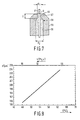
- FIG. 7 shows part of the tubular element 55, in which the feed channel 56 with the constricted entry opening 57 and the guide channel 59 is attached.
- the diameter of the constricted entrance opening is indicated by d i and the diameter of the guide channel by d 2 ; L denotes the length of the entrance opening.
- the convex meniscus D in the constricted entry opening 57 can be clearly seen.
- a constricted entry opening with a diameter d i of 0.9 to 1.1 mm and a length L of 2 mm is suitable for drawing speeds of up to 3 m / s.
- the guide channel 59 had a length of 30 mm and a diameter d 2 of 2 mm.
- a pressure of 300 kPa was maintained in the reservoir.
- a nozzle 40 was used, the outflow opening 41 of which had a diameter of 350 ⁇ m and a length of 3 mm.
- FIG. 5 shows a photographic enlargement (80 ⁇ ), taken by the light transmission method, a fiber F with a diameter of 125 ⁇ m with a coating C with a layer thickness of 60 ⁇ m, applied with the method according to the invention at a drawing speed of 3 m / s; the concentration of bubbles is extremely low; the perceptible bubbles are smaller than 8 to 10 ⁇ m. Fibers that were coated at a drawing speed of 2.5 m / s were completely free of bubbles.
- the thickness of the coating is also influenced by the temperature of the coating material and consequently by the dynamic viscosity of the same. It has been found that the layer thickness can be controlled in a simple and effective manner by regulating the temperature and consequently the viscosity of the coating material by circulation of warm water in the circulation chamber 33 in a precise and slow manner. In this way, the diameter of the coated fiber could be set with an accuracy of ⁇ 0.5 ⁇ m.
- the diagram according to FIG. 8 shows the diameter d of a coated fiber as a function of the temperature T or the dynamic viscosity ⁇ of the coating material.
- the diameter of the uncoated fiber was 125 ⁇ m.
- the diameter of the outflow opening 41 in the nozzle 40 was 260 ⁇ m.
- the coating material used was a commercially available UV-curing acrylate. With increasing temperature T, the diameter d of the coated fiber increases with the outflow opening remaining the same.
- a completely bubble-free coating can also be applied to fibers at drawing speeds of 3 m / s and higher, using a further measure according to the invention, namely by creating and maintaining a gas atmosphere in the vicinity of the inlet opening 57 and above the meniscus D. , the kinematic viscosity of this gas being lower than that of air.
- This gas is supplied via the gas supply 67, flows through the space 50, flows around the inlet opening 57 and the convex meniscus D of the coating material and leaves the space 50 via the central opening 73 in the cover 69. This gas can be discharged again via the gas discharge lines 75 will.
- the draw speed at which a fiber can be coated without bubbling can be further increased by a factor of 4 using a gas whose kinematic viscosity is only 15% of that of air, namely dichlorodifluoromethane.
- FIG. 6 shows the same magnification of 80 ⁇ as FIG. 5, a fiber provided with a coating with a layer thickness of 50 ⁇ m, which was coated at a drawing speed of 12 m / s using C CI2F2 as the purge gas. Even with the enlargement shown, not a single bubble is perceptible.
- the gas was supplied in an amount of 13 cm 3 / s.
- a pressure of 600 kPa was maintained in the storage vessel 85.
- the dimensions of the entrance opening 57 and the guide channel 59 were the same as in the first embodiment. The result has proven to be reproducible over long lengths, ie over lengths of a few kilometers.
- the drawing speed of 12 m / s was the highest speed that the drawing system available for the tests allowed. Because of the extraordinary results and the special effects, it is likely that even higher speeds are possible.
- All parts of the drawing system 1 are aligned exactly with the common center line H-H, with which the center line of the fiber F coincides, so that a radially symmetrical influence on the fiber, namely heating, cooling, curing, is obtained.
- the coating should also be applied coaxially or concentrically to the fiber, i.e. the thickness of the coating should be constant over the circumference of the fiber.
- a fiber with a non-concentric coating is exposed to non-concentric asymmetric forces during cooling and heating. These asymmetrical forces are the result of uneven expansion coefficients of the fiber and coating material and can lead to undesirable changes in the optical properties of the fiber.
- the concentric position of the fiber and the coating is continuously measured with the help of the test device 13.
- An error in the concentricity can be corrected or avoided in a simple manner in the device shown in that the elastically deformable tube element 55, which consists of polytetrafluoroethylene, is adjusted by means of the adjusting screws 79 and, if necessary, bent somewhat.
- the inlet opening 57 can be centered or adjusted in such a way that the coating comes to rest concentrically around the fiber. No further settings or readjustments are required.
- the position of the nozzle 40 with the outflow opening remains unchanged, aligned and coaxial with the center line H-H of the system.
Landscapes
- Engineering & Computer Science (AREA)
- Life Sciences & Earth Sciences (AREA)
- Chemical & Material Sciences (AREA)
- Organic Chemistry (AREA)
- Chemical Kinetics & Catalysis (AREA)
- General Chemical & Material Sciences (AREA)
- Geochemistry & Mineralogy (AREA)
- Materials Engineering (AREA)
- General Life Sciences & Earth Sciences (AREA)
- Manufacturing & Machinery (AREA)
- Optical Fibers, Optical Fiber Cores, And Optical Fiber Bundles (AREA)
- Surface Treatment Of Glass Fibres Or Filaments (AREA)
- Application Of Or Painting With Fluid Materials (AREA)
- Coating Apparatus (AREA)
- Treatment Of Fiber Materials (AREA)
- Paper (AREA)
Claims (12)
Priority Applications (1)
| Application Number | Priority Date | Filing Date | Title |
|---|---|---|---|
| AT86200631T ATE48989T1 (de) | 1985-04-19 | 1986-04-15 | Verfahren und vorrichtung zum beschichten einer faser. |
Applications Claiming Priority (2)
| Application Number | Priority Date | Filing Date | Title |
|---|---|---|---|
| NL8501145 | 1985-04-19 | ||
| NL8501145 | 1985-04-19 |
Publications (2)
| Publication Number | Publication Date |
|---|---|
| EP0200256A1 EP0200256A1 (fr) | 1986-11-05 |
| EP0200256B1 true EP0200256B1 (fr) | 1989-12-27 |
Family
ID=19845862
Family Applications (1)
| Application Number | Title | Priority Date | Filing Date |
|---|---|---|---|
| EP86200631A Expired EP0200256B1 (fr) | 1985-04-19 | 1986-04-15 | Procédé et appareil de revêtement d'une fibre |
Country Status (8)
| Country | Link |
|---|---|
| US (2) | US4704307A (fr) |
| EP (1) | EP0200256B1 (fr) |
| JP (1) | JPH0718083B2 (fr) |
| CN (1) | CN1018820B (fr) |
| AT (1) | ATE48989T1 (fr) |
| AU (1) | AU584692B2 (fr) |
| CA (1) | CA1281521C (fr) |
| DE (1) | DE3667780D1 (fr) |
Cited By (2)
| Publication number | Priority date | Publication date | Assignee | Title |
|---|---|---|---|---|
| FR2674343A1 (fr) * | 1991-03-22 | 1992-09-25 | X Ial | Systeme de formation et de visualisation d'informations dans le champ visuel d'un operateur. |
| NL1009503C2 (nl) | 1998-06-26 | 2000-01-04 | Plasma Optical Fibre Bv | Werkwijze voor het aanbrengen van een beschermende organische deklaag op een optische vezel van glas. |
Families Citing this family (27)
| Publication number | Priority date | Publication date | Assignee | Title |
|---|---|---|---|---|
| NL8501146A (nl) * | 1985-04-19 | 1986-11-17 | Philips Nv | Inrichting voor het bekleden van optische vezels. |
| US4851165A (en) * | 1987-09-02 | 1989-07-25 | American Telephone And Telegraph Company At&T Bell Laboratories | Methods of and apparatus for coating optical fiber |
| DE4010306C2 (de) * | 1990-03-30 | 1999-06-10 | Mag Masch App | Verfahren und Vorrichtung zur Herstellung von Lackdrähten mit Schmelzharzen |
| SE467461B (sv) * | 1990-06-21 | 1992-07-20 | Ericsson Telefon Ab L M | Dubbelbelaeggningskopp |
| US5060593A (en) * | 1990-06-25 | 1991-10-29 | The United States Of America As Represented By The Secretary Of The Army | Device for applying adhesive onto fiber and drying before winding |
| US5156888A (en) * | 1990-09-14 | 1992-10-20 | Hoechst Celanese Corp. | Method and apparatus for applying polymeric coating |
| US5076916A (en) * | 1991-02-04 | 1991-12-31 | Hoechst Celanese Corp. | Device for separating fluid from a fiber following contact |
| DE4201376C1 (fr) * | 1992-01-20 | 1993-01-28 | Herberts Gmbh, 5600 Wuppertal, De | |
| DE9317617U1 (de) * | 1993-11-18 | 1994-01-05 | Kabel Rheydt AG, 41238 Mönchengladbach | Vorrichtung zum Beschichten einer optischen Faser |
| CA2168830A1 (fr) * | 1995-03-23 | 1996-09-24 | John Steele Abbott Iii | Methode et appareil pour enduire des fibres |
| US5665164A (en) * | 1996-01-02 | 1997-09-09 | Milliman; James A. | Co-extrusion cross-head die apparatus |
| US5843231A (en) * | 1996-09-24 | 1998-12-01 | Alcatel Telecommunications Cable | Apparatus for bubble stripping and coating a fiber |
| US6030664A (en) * | 1998-07-15 | 2000-02-29 | Lucent Technologies Inc. | Biconic coating die for making coated optical fibers |
| US6131416A (en) * | 1999-02-08 | 2000-10-17 | Lucent Technologies Inc. | Bubble prevention in coating of filaments |
| KR100318927B1 (ko) * | 2000-01-06 | 2001-12-29 | 윤종용 | 냉각기를 구비한 광섬유 코팅 장치 |
| KR100800758B1 (ko) | 2004-09-15 | 2008-02-01 | 엘에스전선 주식회사 | 광섬유 코팅층에 기포의 발생을 방지하기 위한 광섬유코팅장치 및 이를 이용한 코팅방법 |
| KR100594657B1 (ko) | 2004-11-22 | 2006-07-03 | 엘에스전선 주식회사 | 고속으로 광섬유를 코팅하기 위한 광섬유 코팅장치 및 방법 |
| US20070063369A1 (en) * | 2005-09-19 | 2007-03-22 | Bridgestone Firestone North American Tire, Llc | Method of molding a tire |
| WO2008014604A1 (fr) * | 2006-08-02 | 2008-02-07 | Nanometrix Inc. | Appareil de transfert modulaire et procédé |
| US7735748B1 (en) * | 2006-10-10 | 2010-06-15 | Ingo Werner Scheer | Spray nozzle with improved tip and method of manufacture |
| US8973520B2 (en) * | 2011-03-18 | 2015-03-10 | Microcrystal Technology Corp. | Coating machine for coating fiber yarns |
| CN104032506B (zh) * | 2014-05-28 | 2016-06-01 | 苏州潮盛印花制版实业有限公司 | 一种管筒上浆装置 |
| JP6394186B2 (ja) * | 2014-08-28 | 2018-09-26 | ブラザー工業株式会社 | 布接着装置 |
| EP3395775B1 (fr) | 2017-04-24 | 2019-06-12 | Corning Incorporated | Procédé d'application de revêtement liquide sur une fibre optique |
| NL2019098B1 (en) * | 2017-04-24 | 2018-11-05 | Corning Inc | Method of applying coating liquid to an optical fiber |
| WO2019182060A1 (fr) * | 2018-03-22 | 2019-09-26 | 住友電気工業株式会社 | Procédé de fabrication de fibre optique et dispositif de fabrication |
| CN109437600B (zh) * | 2018-11-16 | 2023-11-21 | 法尔胜泓昇集团有限公司 | 一种方便拆卸的高效光纤涂覆除气泡装置 |
Citations (1)
| Publication number | Priority date | Publication date | Assignee | Title |
|---|---|---|---|---|
| US4409263A (en) * | 1982-01-27 | 1983-10-11 | Western Electric Co., Inc. | Methods of and apparatus for coating lightguide fiber |
Family Cites Families (11)
| Publication number | Priority date | Publication date | Assignee | Title |
|---|---|---|---|---|
| US4116654A (en) * | 1977-02-22 | 1978-09-26 | E. I. Du Pont De Nemours And Company | Low attenuation, high strength optical fiber with silica filament core |
| US4194462A (en) * | 1978-08-21 | 1980-03-25 | Corning Glass Works | Optical waveguide coating assembly |
| GB2048726A (en) * | 1979-03-05 | 1980-12-17 | Post Office | Coating Optical Fibres |
| US4246299A (en) * | 1979-06-07 | 1981-01-20 | Corning Glass Works | Method of coating optical waveguide filaments |
| US4490415A (en) * | 1980-09-26 | 1984-12-25 | Asahi Kasei Kogyo Kabushiki Kaisha | Method of coating a pencil |
| US4349587A (en) * | 1981-03-12 | 1982-09-14 | Bell Telephone Laboratories, Incorporated | Method for coating fiber waveguides |
| US4374161A (en) * | 1981-04-24 | 1983-02-15 | Bell Telephone Laboratories, Incorporated | Pressure coating of fibers |
| US4533570A (en) * | 1982-04-19 | 1985-08-06 | At&T Technologies, Inc. | Method and apparatus for coating optical waveguide fibers |
| US4439467A (en) * | 1982-09-15 | 1984-03-27 | Western Electric Company, Inc. | Methods of coating lightguide fiber and product produced thereby |
| US4539226A (en) * | 1984-03-02 | 1985-09-03 | At&T Technologies, Inc. | High speed lightguide coating apparatus |
| NL8501146A (nl) * | 1985-04-19 | 1986-11-17 | Philips Nv | Inrichting voor het bekleden van optische vezels. |
-
1986
- 1986-04-15 DE DE8686200631T patent/DE3667780D1/de not_active Expired - Lifetime
- 1986-04-15 EP EP86200631A patent/EP0200256B1/fr not_active Expired
- 1986-04-15 AT AT86200631T patent/ATE48989T1/de active
- 1986-04-16 AU AU56169/86A patent/AU584692B2/en not_active Ceased
- 1986-04-16 CN CN86103285A patent/CN1018820B/zh not_active Expired
- 1986-04-16 CA CA000506778A patent/CA1281521C/fr not_active Expired - Lifetime
- 1986-04-17 US US06/853,295 patent/US4704307A/en not_active Expired - Lifetime
- 1986-04-19 JP JP61089227A patent/JPH0718083B2/ja not_active Expired - Fee Related
-
1987
- 1987-07-02 US US07/069,746 patent/US4765271A/en not_active Expired - Fee Related
Patent Citations (1)
| Publication number | Priority date | Publication date | Assignee | Title |
|---|---|---|---|---|
| US4409263A (en) * | 1982-01-27 | 1983-10-11 | Western Electric Co., Inc. | Methods of and apparatus for coating lightguide fiber |
Cited By (2)
| Publication number | Priority date | Publication date | Assignee | Title |
|---|---|---|---|---|
| FR2674343A1 (fr) * | 1991-03-22 | 1992-09-25 | X Ial | Systeme de formation et de visualisation d'informations dans le champ visuel d'un operateur. |
| NL1009503C2 (nl) | 1998-06-26 | 2000-01-04 | Plasma Optical Fibre Bv | Werkwijze voor het aanbrengen van een beschermende organische deklaag op een optische vezel van glas. |
Also Published As
| Publication number | Publication date |
|---|---|
| AU5616986A (en) | 1986-11-06 |
| JPS61258062A (ja) | 1986-11-15 |
| US4704307A (en) | 1987-11-03 |
| AU584692B2 (en) | 1989-06-01 |
| DE3667780D1 (de) | 1990-02-01 |
| CN86103285A (zh) | 1987-04-22 |
| JPH0718083B2 (ja) | 1995-03-01 |
| EP0200256A1 (fr) | 1986-11-05 |
| US4765271A (en) | 1988-08-23 |
| CN1018820B (zh) | 1992-10-28 |
| ATE48989T1 (de) | 1990-01-15 |
| CA1281521C (fr) | 1991-03-19 |
Similar Documents
| Publication | Publication Date | Title |
|---|---|---|
| EP0200256B1 (fr) | Procédé et appareil de revêtement d'une fibre | |
| DE3042668C2 (fr) | ||
| EP0198561B1 (fr) | Appareil pour revêtir une fibre | |
| DE3301788C2 (fr) | ||
| DE2906071C2 (de) | Verfahren zum Ziehen einer Faser aus thermoplastischem Material zur Herstellung optischer Wellenleiter | |
| DE2035081C3 (de) | Vorrichtung zum kontinuierlichen Auftragen eines Glätte- oder Verfestigungsmittels auf einen laufenden Textilfaden | |
| DE3010481A1 (de) | Verfahren und vorrichtung zum herstellen optischer fasern sowie nach diesem verfahren hergestellte optische fasern | |
| DE2653836B2 (de) | Verfahren und Vorrichtung zum Ziehen optischer Fasern | |
| DE2736441A1 (de) | Verfahren zur beschichtung von endlosen traegerbahnen | |
| DE3000109A1 (de) | Glasfaserkabel, verfahren zu seiner herstellung sowie vorrichtung zur durchfuehrung des verfahrens | |
| DE2850969A1 (de) | Einrichtung zum ziehen eines fadens von einem erhitzten rohling aus thermoplastischem material | |
| EP0087757A1 (fr) | Dispositif de fabrication d'un câble électrique et/ou optique | |
| DE2164545C3 (de) | Verfahren und Vorrichtung zur kontinuierlichen Kühlung aufeinanderfolgender Abschnitte eines thermoplastischen Stranges | |
| EP0937560A1 (fr) | Fabrication de produits thermoplastiques renforcés unidirectionnellement | |
| EP0907103A1 (fr) | Procédé et dispositif pour le revêtement par rideau d'un support en mouvement | |
| EP0176937A2 (fr) | Procédé de fabrication de fil non texturé | |
| DE3822093A1 (de) | Entgasungs- und entschaeumungsverfahren und vorrichtung zur durchfuehrung dieses verfahrens | |
| DE3240245A1 (de) | Vorrichtung zum herstellen von bandfoermigen siliziumkoerpern fuer solarzellen | |
| DE1704435A1 (de) | Verfahren und Vorrichtung zum Herstellen eines rohrfoermigen Films oder von Rohren aus thermoplastischem Harz | |
| DE2203973A1 (de) | Verfahren und vorrichtung zum befeuchten einer bahn | |
| DE69708495T2 (de) | Vorrichtung und Verfahren zur Beschichtung von optischen Fasern | |
| DE69200578T2 (de) | Vorrichtung zur Beschichtung von optischen Fasern oder Strängen von optischen Fasern mit Harz. | |
| EP0838440A1 (fr) | Procédé et dispositif de refroidissement d'une fibre optique en verre étirée à partir d'une préforme en verre | |
| DE1957033A1 (de) | Verfahren zum Herstellen von Zinnschichten oder Zinnlegierungsschichten auf Draht aus Kupfer oder Kupferlegierungen durch Feuerverzinnen und Vorrichtung zur Durchfuehrung des Verfahrens | |
| DE2445827B2 (de) | Verfahren zur herstellung langgestreckter glaskoerper aus entglasbarem glas |
Legal Events
| Date | Code | Title | Description |
|---|---|---|---|
| PUAI | Public reference made under article 153(3) epc to a published international application that has entered the european phase |
Free format text: ORIGINAL CODE: 0009012 |
|
| AK | Designated contracting states |
Kind code of ref document: A1 Designated state(s): AT BE CH DE FR GB IT LI NL SE |
|
| XX | Miscellaneous (additional remarks) |
Free format text: EIN ANTRAG GEMAESS REGEL 88 EPUE AUF BERICHIGUNG (HINZUFUEGUNG) DER FIGUREN 7 UND 8 LIEGT VOR.UEBERDIESEN ANTRAG WIRD IM LAUFE DES VERFAHRENS VON DER PRUEFUNGSABTEILUNG EINE ENTSCHEIDUNG GETROFFEN WERDEN. |
|
| 17P | Request for examination filed |
Effective date: 19870504 |
|
| 17Q | First examination report despatched |
Effective date: 19880413 |
|
| GRAA | (expected) grant |
Free format text: ORIGINAL CODE: 0009210 |
|
| DX | Miscellaneous (deleted) | ||
| AK | Designated contracting states |
Kind code of ref document: B1 Designated state(s): AT BE CH DE FR GB IT LI NL SE |
|
| REF | Corresponds to: |
Ref document number: 48989 Country of ref document: AT Date of ref document: 19900115 Kind code of ref document: T |
|
| REF | Corresponds to: |
Ref document number: 3667780 Country of ref document: DE Date of ref document: 19900201 |
|
| ITF | It: translation for a ep patent filed | ||
| PGFP | Annual fee paid to national office [announced via postgrant information from national office to epo] |
Ref country code: BE Payment date: 19900329 Year of fee payment: 5 |
|
| GBT | Gb: translation of ep patent filed (gb section 77(6)(a)/1977) | ||
| ET | Fr: translation filed | ||
| PGFP | Annual fee paid to national office [announced via postgrant information from national office to epo] |
Ref country code: SE Payment date: 19900425 Year of fee payment: 5 |
|
| PGFP | Annual fee paid to national office [announced via postgrant information from national office to epo] |
Ref country code: AT Payment date: 19900427 Year of fee payment: 5 |
|
| PGFP | Annual fee paid to national office [announced via postgrant information from national office to epo] |
Ref country code: NL Payment date: 19900430 Year of fee payment: 5 |
|
| PLBE | No opposition filed within time limit |
Free format text: ORIGINAL CODE: 0009261 |
|
| STAA | Information on the status of an ep patent application or granted ep patent |
Free format text: STATUS: NO OPPOSITION FILED WITHIN TIME LIMIT |
|
| 26N | No opposition filed | ||
| PG25 | Lapsed in a contracting state [announced via postgrant information from national office to epo] |
Ref country code: AT Effective date: 19910415 |
|
| PG25 | Lapsed in a contracting state [announced via postgrant information from national office to epo] |
Ref country code: SE Effective date: 19910416 |
|
| PG25 | Lapsed in a contracting state [announced via postgrant information from national office to epo] |
Ref country code: BE Effective date: 19910430 |
|
| BERE | Be: lapsed |
Owner name: PHILIPS' GLOEILAMPENFABRIEKEN N.V. Effective date: 19910430 |
|
| PG25 | Lapsed in a contracting state [announced via postgrant information from national office to epo] |
Ref country code: NL Effective date: 19911101 |
|
| NLV4 | Nl: lapsed or anulled due to non-payment of the annual fee | ||
| ITTA | It: last paid annual fee | ||
| EUG | Se: european patent has lapsed |
Ref document number: 86200631.9 Effective date: 19911108 |
|
| ITPR | It: changes in ownership of a european patent |
Owner name: CAMBIO RAGIONE SOCIALE;PHILIPS ELECTRONICS N.V. |
|
| REG | Reference to a national code |
Ref country code: CH Ref legal event code: PFA Free format text: PHILIPS ELECTRONICS N.V. |
|
| REG | Reference to a national code |
Ref country code: FR Ref legal event code: CD |
|
| REG | Reference to a national code |
Ref country code: CH Ref legal event code: PUE Owner name: PHILIPS ELECTRONICS N.V. TRANSFER- PLASMA OPTICAL |
|
| REG | Reference to a national code |
Ref country code: GB Ref legal event code: 732E |
|
| REG | Reference to a national code |
Ref country code: FR Ref legal event code: TP |
|
| REG | Reference to a national code |
Ref country code: CH Ref legal event code: NV Representative=s name: ISLER & PEDRAZZINI AG |
|
| REG | Reference to a national code |
Ref country code: GB Ref legal event code: IF02 |
|
| PGFP | Annual fee paid to national office [announced via postgrant information from national office to epo] |
Ref country code: FR Payment date: 20040210 Year of fee payment: 19 |
|
| PGFP | Annual fee paid to national office [announced via postgrant information from national office to epo] |
Ref country code: GB Payment date: 20040414 Year of fee payment: 19 Ref country code: CH Payment date: 20040414 Year of fee payment: 19 |
|
| PGFP | Annual fee paid to national office [announced via postgrant information from national office to epo] |
Ref country code: DE Payment date: 20040430 Year of fee payment: 19 |
|
| PG25 | Lapsed in a contracting state [announced via postgrant information from national office to epo] |
Ref country code: IT Free format text: LAPSE BECAUSE OF NON-PAYMENT OF DUE FEES;WARNING: LAPSES OF ITALIAN PATENTS WITH EFFECTIVE DATE BEFORE 2007 MAY HAVE OCCURRED AT ANY TIME BEFORE 2007. THE CORRECT EFFECTIVE DATE MAY BE DIFFERENT FROM THE ONE RECORDED. Effective date: 20050415 Ref country code: GB Free format text: LAPSE BECAUSE OF NON-PAYMENT OF DUE FEES Effective date: 20050415 |
|
| PG25 | Lapsed in a contracting state [announced via postgrant information from national office to epo] |
Ref country code: LI Free format text: LAPSE BECAUSE OF NON-PAYMENT OF DUE FEES Effective date: 20050430 Ref country code: CH Free format text: LAPSE BECAUSE OF NON-PAYMENT OF DUE FEES Effective date: 20050430 |
|
| PG25 | Lapsed in a contracting state [announced via postgrant information from national office to epo] |
Ref country code: DE Free format text: LAPSE BECAUSE OF NON-PAYMENT OF DUE FEES Effective date: 20051101 |
|
| REG | Reference to a national code |
Ref country code: CH Ref legal event code: PL |
|
| GBPC | Gb: european patent ceased through non-payment of renewal fee |
Effective date: 20050415 |
|
| PG25 | Lapsed in a contracting state [announced via postgrant information from national office to epo] |
Ref country code: FR Free format text: LAPSE BECAUSE OF NON-PAYMENT OF DUE FEES Effective date: 20051230 |
|
| REG | Reference to a national code |
Ref country code: FR Ref legal event code: ST Effective date: 20051230 |