EP0200309A2 - Gas insulation metal-clad power equipment - Google Patents
Gas insulation metal-clad power equipment Download PDFInfo
- Publication number
- EP0200309A2 EP0200309A2 EP86301510A EP86301510A EP0200309A2 EP 0200309 A2 EP0200309 A2 EP 0200309A2 EP 86301510 A EP86301510 A EP 86301510A EP 86301510 A EP86301510 A EP 86301510A EP 0200309 A2 EP0200309 A2 EP 0200309A2
- Authority
- EP
- European Patent Office
- Prior art keywords
- bushing
- conductor
- gas
- cylindrical
- insulating
- Prior art date
- Legal status (The legal status is an assumption and is not a legal conclusion. Google has not performed a legal analysis and makes no representation as to the accuracy of the status listed.)
- Granted
Links
Images




Classifications
-
- H—ELECTRICITY
- H02—GENERATION; CONVERSION OR DISTRIBUTION OF ELECTRIC POWER
- H02B—BOARDS, SUBSTATIONS OR SWITCHING ARRANGEMENTS FOR THE SUPPLY OR DISTRIBUTION OF ELECTRIC POWER
- H02B11/00—Switchgear having carriage withdrawable for isolation
- H02B11/26—Arrangements of fuses, resistors, voltage arresters or the like
-
- H—ELECTRICITY
- H01—ELECTRIC ELEMENTS
- H01B—CABLES; CONDUCTORS; INSULATORS; SELECTION OF MATERIALS FOR THEIR CONDUCTIVE, INSULATING OR DIELECTRIC PROPERTIES
- H01B17/00—Insulators or insulating bodies characterised by their form
- H01B17/26—Lead-in insulators; Lead-through insulators
- H01B17/30—Sealing
- H01B17/301—Sealing of insulators to support
-
- H—ELECTRICITY
- H01—ELECTRIC ELEMENTS
- H01B—CABLES; CONDUCTORS; INSULATORS; SELECTION OF MATERIALS FOR THEIR CONDUCTIVE, INSULATING OR DIELECTRIC PROPERTIES
- H01B17/00—Insulators or insulating bodies characterised by their form
- H01B17/26—Lead-in insulators; Lead-through insulators
- H01B17/30—Sealing
- H01B17/303—Sealing of leads to lead-through insulators
- H01B17/308—Sealing of leads to lead-through insulators by compressing packing material
-
- H—ELECTRICITY
- H02—GENERATION; CONVERSION OR DISTRIBUTION OF ELECTRIC POWER
- H02B—BOARDS, SUBSTATIONS OR SWITCHING ARRANGEMENTS FOR THE SUPPLY OR DISTRIBUTION OF ELECTRIC POWER
- H02B11/00—Switchgear having carriage withdrawable for isolation
- H02B11/02—Details
- H02B11/04—Isolating-contacts, e.g. mountings or shieldings
Definitions
- the present invention relates generally to a gas insulation metal-clad power equipment, and more particularly to the metal-clad power equipment provided with a single or plural conductors disposed passing through a compartment wall of the equipment filled with an insulating gas.
- the size or dimensions of the insulating bushing are inevitably increased outside the bus compartment in order to prevent flashover (dielectric breakdown on or along the surface of : an insulator) from being generated between the conductor and the wall within air ambience.
- flashover voltage is intended to be increased in dependence upon only an increase in flashover distance (distance along the surface of the insulator).
- the flashover distance is excessively increased, there exists another problem in that dielectric breakdown may occur between the conductor and the wall directly through inside the insulating bushing without occurrence of flashover along the surface of the insulator, thus it being impossible to effectively increase flashover voltage.
- the advantage of the use of gas insulation metal-clad power equipment is to reduce the size of the equipment.
- the size or the dimensions of the insulating bushing is excessively great, it is impossible to effectively reduce the size of the whole power equipment by making the best use of the advantage of the gas thus insulation, resulting in a high cost, a heavy weight, and a large installation space, etc.
- a gas insulation metal-clad power equipment filled with an insulating gas for housing a power device having: - a grounded compartment wall including a grounded compartment wall member; - a cylindrical insulating bushing air-tightly fixed to the grounded wall member formed with a through hole; and - a loaded conductor supported by said cylindrical insulating bushing at a center thereof for connecting the power device housed inside said power equipment to another device installed outside said power equipment, the conductor being passed through an inner cylindrical space of said bushing filled with the insulating gas
- one end of said cylindrical bushing is air-tightly fixed to said grounded compartment wall member in such a way that an outer circumferential surface of said loaded conductor directly faces an inner circumferential surface of the through hole formed in said grounded compartment wall member with a space distance g filled with an insulating gas and without any intervening portion of said cylindrical bushing, the outer circumferential surface of said loaded conductor being air-tightly supported by the other bottom end of said
- a difference between a diameter ⁇ 2 of the inner cylindrical space and a diameter ⁇ 1 of the through hole is equal to or larger than 4 mm ( ⁇ 2 - ⁇ 1 ⁇ 4).
- an insertion distance B of an end of the inner fixed conductor into the inner cylindrical space is equal to or longer than one-fifth of a distance g between the circumferential surface of the through hole and an outer circumferential surface of the conductor (B > g/5).
- the dielectric strength between the conductor and the grounded compartment wall is rather dependent upon dielectric strength against dielectric breakdown within insulating gas ambience, than dependent upon that against flashover within air ambience, thus making the best use of the presence of insulating gas.
- Fig. 1 shows a gas insulation enclosed switchgear by way of example of the gas insulation metal-clad power equipment.
- the gas insulation switchgear compartment 1 of cubicle type is divided into two of a circuit breaker compartment 2 and a bus compartment 3 by a grounded metallic compartment wall 4.
- the compartment wall 4 there is disposed two cylindrical insulating bushings 3A and 5B made of plastics or porcelain and fixed to the compartment wall 4 penetrating therethrough. Passing through a center of each cylindrical insulating bushing 5A or 5B, an inner fixed conductor 6A or 6B is fixed to the bushing at one end thereof and connected to a power supply bus or a load bus (both not shown), respectively, at the other end thereof.
- a truck type circuit breaker 7 is movably housed.
- the breaker 7 is provided with two outer movable conductors 8A and 8B so as to be connected to or disconnected from the inner fixed conductors 5A and 5B, respectively, when moved to and fro within the breaker compartment 2.
- bus bars (not shown) are arranged.
- This bus compartment 3 is filled with an insulating gas such as SF 6 (sulfur hexafluoride gas), for instance, or a mixture of the gas and air under a pressure equal to or higher than the atmospheric pressure (0.10 to 0.2 MPa).
- the present invention closely relates to the cylindrical insulating bushing 5A or 5B. Therefore, only the cylindrical insulating bushing will be described in further detail with reference to Fig. 2.
- a through hole 41 is formed in the grounded metallic compartment wall 4, through which the cylindrical insulating bushing 5 is disposed and fixed.
- the bushing 5 is formed with a cylindrical wall 51, an bottom end 52 and a flange 53.
- the flange 53 is air-tightly fixed to the compartment wall 4 from the outside via a sealing member such as an O ring 54 by use of bolts 55.
- the inner fixed conductor 6 is also air- tightly fixed to the bottom end 52 of the bushing 5 via a sealing member such as another O ring 56, being passed through the center of the bushing 5 .
- 0 1 denotes a diameter of the through hole 41 formed in the wall 4
- 0 2 denotes an inner diameter of the inner cylindrical wall 51 of the bushing 5
- ⁇ 3 denotes an outer diameter of the cylindrical wall 51 of the bushing 5 which is smaller than ⁇ 1
- L i denotes an inner projection length of the bushing (between the inner surface of the wall 4 and the inner end surface of the cylindrical wall 51 of the bushing 5 )
- L o denotes an outer projection length of the bushing (between the outer surface of the wall 4 and an outer surface of the bottom end 5 2 of the bushing 5)
- a ( ⁇ 1 - ⁇ 3 ) denotes a gap between the circumferential surface of the through hole 41 and the outer circumferential surface of the cylindrical wall 51 of the bushing 5.
- Fig. 3 shows a model of the bushing 5 equivalent to that shown in Fig. 2 from the insulation standpoint.
- a high voltage is applied to the conductor 6 and the metallic compartment wall 4 is grounded as shown.
- the insulating bushing 5 has no bottom end 52. This is because various experiments have indicated that the bottom end 52 of the bushing 5 exerts neither a good or bad influence upon the flashover characteristics. This may be natural because when a high voltage is applied between the inner fixed conductor 6 and the compartment wall 4, flashover will occur between the along an outer cylindrical surface of the cylindrical wall 51 of the bushing 5.
- Fig. 4 shows test results of the relationship between the dielectric breakdown voltage (50% in occurrence probability) and the outer projection length L of the bushing 5.
- a positive polarity impulse voltage and a negative polarity impulse voltage have been applied to the conductor 6, independently.
- Each impulse voltage (1.2 x 50 ⁇ s) has a pulse rise time of about 1. 2 ⁇ s and a pulse width of about 50 ⁇ s.
- Fig. 5 shows an enclosed switchgear by way of example, to which a first embodiment of the cylindrical insulating bushing according to the present invention is applied.
- the gas insulation enclosed switchgear 1 shown in Fig. 5 is the same in structure as the prior art one shown in Fig. 1 except the insulating bushings 100A and 100B. Therefore, the structural features and functional effects of this enclosed switchgear other than those of the insulating bushings are substantially the same as with the prior art ones previously described.
- the same references have been retained for similar parts or sections which have the same functions and any detailed description of them is believed to be unnecessary.
- a cylindrical insulating bushing 100A according to the present invention is fixed to the metallic compartment wall 4 projecting toward the outside, in particularly toward the outer atmosphere side, without penetrating through the wall 4 .
- This structure of the cylindrical insulating bushing 1 0 0 A is the primary feature of the present invention.
- the above structure will be described in further detail with reference to Fig. 6.
- the bushing 100 made of plastics or porcelain according to the present invention is formed with a cylindrical wall 101, a bottom end 1 0 2 and a flange surface 103.
- the flange surface 1 03 is air-tightly fixed to the grounded metallic compartment wall 4 through a sealing member such as an 0 ring 54 by use of bolts 55.
- the inner fixed conductor 6 is air-tightly fixed to the bottom end 102 of the bushing 100 at its center through a sealing member such as another 0 ring 56 passing through the inner cylindrical space thereof.
- 0 1 denotes a diameter of the through hole 41 formed in the wall 4
- 0 2 denotes an inner diameter of the cylindrical wall 101 and the flange 103 of the bushing 100 which is larger than ⁇ 1
- f denotes a length of the inner projecting cylindrical space of the bushing 1 00
- g denotes a distance between the circumferential surface of the through hole 41 and the outer circumferential surface of the inner fixed conductor 6
- d denotes the diameter of the conductor 6.
- the length ⁇ of the inner cylindrical space is roughly equal to the distance g between the through hole 41 and the conductor 6; the inner diameter 0 2 of the bushing 100 is greater than the diameter 0 1 of the through hole 41; and the diameter ⁇ 1 of the through hole 41 is smaller about 5 mm than the inner diameter 0 2 of the bushing 100.
- the reason why ⁇ 1 is smaller than 0 2 is to positively allow dielectric breakdown to be produced between the grounded metallic wall 4 and the conductor 6. Further, the through hole 41 is deburred from both the sides.
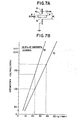
- Fig. 7A illustrates the test conditions in which a through hole 41 is formed in the wall 4 and only the conductor 6 is passed therethrough.
- the thickness of the wall 4 is 1.2 mm; the diameter of the conductor (aluminum rod) 6 is 30 mm.
- the diameter 0 1 of the through hole 4 1 is changed to vary the distance g between the hole 41 and the conductor 6.
- the test box within which the above wall 4 and conductor 6 are housed is first evacuated and then filled with 100% SF 6 gas at the atmospheric pressure (about 0.1 MPa). A high test voltage is applied to the conductor 6, and the wall 4 is grounded.
- the positive and negative polarity impulse dielectric breakdown voltages have been determined for each distance g when breakdown occurs in 50% or more probability.
- Fig. 7B shows the test results, which indicate that (1) the breakdown voltage increases in proportion to the distance g or the hole diameter ⁇ 1 against both positive and negative polarity impulse high voltages, and (2) the positive polarity impulse breakdown voltage is higher than the negative one.
- Fig. 8A illustrates the test conditions, in which the cylindrical insulating bushing 100 having a length f in the inner cylindrical space and made of a , bakelite material is air-tightly fixed to the outer surface of the wall 4 under condition ⁇ 1 ⁇ 0 2 .
- the conductor 6 is also air-tightly passed through the cylindrical bushing 100.
- the test box having the wall 4 and the bushing 100 is filled with a gas of SF 6 at the atmospheric pressure (about 0.10 MPa).
- the wall thickness is 1.2 mm
- the conductor diameter d is 30 mm.
- the dimensions are as follows:
- the length 1 of the bushing 100 is changed.
- a high test voltage is applied to the conductor 6 and the wall 4 is grounded.
- the positive and negative polarity impulse breakdown voltages have been determined for each length 1 when breakdown occurs in 50% probability.
- Fig. 8B shows the test results,
- Fig. 9 shows the other test results similar to those shown in Fig. 8B.
- the test conditions of Fig. 9 roughly correspond to the first test shown in Fig. 8B as follows:
- the above test results shown in Fig. 9 indicates that the breakdown voltage is roughly saturated when ( ⁇ 2 - ⁇ 1 )/2 is 2 mm or more, and sharply lowered when (02 - ⁇ 1 )/2 is less than 2 mm.
- the length f of the inner cylindrical space of the cylindrical insulating bushing 100 is effective upon an improvement in insulation withstand voltage when l ⁇ g/4.
- the high saturated positive and negative polarity impulse breakdown voltages can be obtained when ( ⁇ 2 - ⁇ 1 )/2 ⁇ 2 mm; that is, when the diameter ⁇ 1 of the wall hole 41 is reduced by 4 mm as compared with the inner diameter 0 2 of the bushing 100.
- the inner edge of the through hole 41 is deburred.
- the impulse voltage (1.2 x 50 ⁇ s) of only the negative polarity has been applied to the conductor. This is because dielectric breakdown voltage in the embodiments of the invention is usually lower in negative polarity than in positive polarity, so that it is possible to know the tendency of the insulation characteristics when negative impulse test voltages are applied to the conductor.
- Fig. 11B indicates that the breakdown voltage is relatively low when l varies between 0 and 10 mm, but almost similar to that shown in Fig. 11A when l ranges between 40 and 100 mm without being subjected to the change of the length l Further, although the breakdown voltage is a little (about 5 kV) improved, it is possible to determine that there exists no marked difference between the two embodiments; that is, it is unnecessary to round the edge of the wall if the wall edge is deburred.
- cylindrical insulating bushing according to the present invention can be applied to other enclosed switchgears as described hereinbelow with reference to the attached drawings.
- Fig. 13 shows the second embodiment of the cylindrical insulating bushing 140 according to the present invention formed with another cylindrical extension 141 having plural annular grooves 141a for increasing the flashover distance within air ambience.
- the length l of the inner cylindrical space of the bushing 140 is determined to be l ⁇ g/4.
- another cylindrical insulating bushing 140a as shown by the dot-dot-dashed lines in Fig. 13, within the switchgear 1.
- a communication passage 140a-1 is formed in the bushing 140a or the space enclosed by two bushings 140 and 140a is filled with another insulation gas.
- Fig. 14 shows another gas insulation enclosed switchgear by way of example, to which the third embodiment of the cylindrical insulating bushing according to the present invention is applied.
- the enclosed switchgear 1 shown in Fig. 14 is the same in structure as that shown in Fig. 5 except the inner movable conductor 6A-1 or 6B-1 and the inner fixed conductor 6A-2 or 6B-2. Therefore, the same references have been retained for similar parts or sections without any description thereof.
- the feature of the switchgear 1 is to disconnect the truck-type circuit breaker 7 from the inner fixed conductors 6A-2 and 6B-2 within the insulating gas ambience. This is because it is possible to increase the insulation withstand voltage as compared when the circuit breaker 7 is disconnected within air ambience and therefore to reduce the disconnected distance between two.
- the inner fixed conductor 6 shown in Fig. 14 is divided into an inner movable conductor 6-1 and an inner fixed conductor 6-2.
- the inner movable conductor 6A-1 or 6B-1 is movably supported by the cylindrical bushing 100, respectively.
- the inner movable conductor 6A-1 or 6B-1 is connected to or disconnected from an outer movable conductor 8A or 8B of the circuit breaker 7 outside the switchgear 1 and further to or from the inner fixed conductor 6A-2 or 6B-2 inside the switchgear box 1.
- the inner movable conductors 6A-1 and 6B-1 are first disconnected from the inner fixed conductors 6A-2 and 6B-2 under non-loaded condition within the compartment 3 by moving the truck-type circuit breaker 7.
- the movable conductors 6A-1 and 6B-1 are still in contact with the outer movable conductors 8A or 8B.
- the outer movable conductors 8A and 8B are disconnected from the inner movable conductors 6A-1 and 6B-1 under non-loaded condition in air ambience.
- Fig. 15 shows the third embodiment of the cylindrical insulating bushing according to the present invention.
- the inner movable conductor 6-1, the second inner fixed conductor 6-2, and the cylindrical insulating bushing 100 are enlarged in further detail.
- the inner movable conductor 6-1 is air-tightly and movably disposed passing through the bottom end surface 102 of the bushing 100 via a sealing member 56.
- the reference numeral 57 denotes a stop ring fixed to the inner movable conductor 6-1 at an appropriate position. It may be preferable to cover the conductor 6-1 by an appropriate insulating material outside the bushing for safety.
- the inner fixed conductor 6-2 is formed with a multiple contact 59 at its end so as to be engageable with the end of the movable conductor 6-1 when the conductor 6-1 is moved toward the right side in Fig. 15.
- the end of the second fixed conductor 6-2 projects by a distance B beyond the through hole 41 formed in the grounded metallic compartment wall 4 into the inner space of the bushing 100.
- d 30 mm
- G connection gap between two conductors
- g 30 mm
- ⁇ 1 90 mm
- ⁇ 2 95 mm
- B 18 mm
- l 110 mm.
- Figs. 17A and 17B show the fourth embodiment of the cylindrical insulating bushing according to the present invention.
- a cylindrical insulating bushing 150 is movably passed through a through hole 41 formed in the grounded metallic compartment wall 4.
- the bushing 150 is supported-by an elastic bushing cover 60 such as a conical metalic bellows.
- the top portion of the bushing cover 60 is air-tightly fixed to the flange portion 153 of the bushing 150 by bolts.
- the bottom portion of the bushing cover 60 is air-tightly fixed to the compartment wall 4 by bolts via an annular metal mounting base 61 having O rings 62 disposed between the wall 4 and the base 61.
- the through hole 63 formed in the top portion of the bushing cover 60 is smaller in diameter than the inner diameter of the bushing 150.
- the reference numeral 64 denotes a shock absorbing stopper member made of rubber and attached to the flange portion 153 of the bushing 150.
- a inner fixed conductor 6-2 is supported by a plastics or porcelain insulator 9 within the switchgear 1.
- An inner movable conductor 6-1 is fixed to the center of the bushing 150. Both the ends of the movable inner conductor 6-1 is so designed as to be engageable with or disengageable from the end of the inner fixed conductor 6-2 or the end of the outer movable conductor 8 as shown in Figs. 17A and 17B.
- the inner movable conductor 6-1 is covered by an extension of the bushing 150 outside the switchgear 1.
- the outer conductor 8 When the circuit breaker 7 is moved into the compartment 1, the outer conductor 8 is first brought into contact with the inner movable conductor 6-1 and then pushes the bushing 150 inside, so that the bushing cover 60 is also pushed inside until the inner movable conductor 6-1 is engaged with the inner fixed conductor 6-2, as shown in Fig. 17A.
- the bushing cover 60 is grounded through the wall 4. Therefore, dielectric breakdown occurs between the bushing cover 60 and the inner movable conductor 6-1.
- the dimensions of the bushing 150 are of course determined so as to satisfy the conditions already explained in detail hereinabove.
- the cylindrical insulating bushing is fixed to the compartment wall so as to project from the wall outside the compartment.
- the bushing is fixed to the grounded metallic compartment wall in such a way as to project from the compartment wall toward inside or outside and since the axial length l of the inner cylindrical space of the bushing is so determined as to be I > g/4 (g: the distance between the surface of through hole and the conductor), it is possible to increase the insulation withstand voltage between the conductor passing through the bushing and the grounded metallic compartment wall without generating dielectric breakdown along the surface of the bushing.
- the difference in diameter between the through hole ⁇ 1 formed in the compartment wall and the inner cylindrical space 0 2 of the bushing is determined to be equal to or larger than 4 mm, it is possible to further reliably prevent dielectric breakdown from being generated along the bushing surface.
- the insertion distance B of the conductor into the inner cylindrical space of the bushing is determined to be equal to or longer than g/5 to prevent dielectric breakdown from being generated along the bushing surface.
- cylindrical insulating bushing since dielectric breakdown occurs between the grounded compartment wall and the conductor within insulation gas ambient rather than dielectric breakdown along the surface of the bushing within air ambient, it is possible to effectively reduce the size, space, weight, cost, etc. of the cylindrical insulating bushing provided for a gas insulation gas metal-clad power equipment.
Landscapes
- Engineering & Computer Science (AREA)
- Power Engineering (AREA)
- Insulators (AREA)
- Gas-Insulated Switchgears (AREA)
- Installation Of Bus-Bars (AREA)
Abstract
Description
- The present invention relates generally to a gas insulation metal-clad power equipment, and more particularly to the metal-clad power equipment provided with a single or plural conductors disposed passing through a compartment wall of the equipment filled with an insulating gas.
- It is well known that dielectric strength of insulating gas or a mixture of insulating gas and air is greater than in air. Therefore, when high voltage devices for metal-clad power equipment are housed within a compartment filled with insulating gas, it is possible to reduce the size or the installation space of the power equipment.
- In practice, however, it is usually impossible to house the whole high-voltage devices within the compartment filled with the insulating gas, because some devices should often be connected to or disconnected from another device installed outside the compartment or be checked in the outside for inspection or maintenance.
- Taking the case of an enclosed switchgear as an example of gas insulation metal-clad power equipment, power supply bus bars and load side bus bars are all housed within a grounded metal-clad bus compartment filled with insulating gas, but a circuit interrupter is installed outside the bus compartment in air. Therefore, in order to connect the devices housed within the bus compartment to those installed outside, some conductors should be disposed passing through the wall of the metal-clad compartment. The conductors should of course be insulated from the grounded compartment wall by appropriate insulating bushings. Various insulating bushings for insulating the conductor from the grounded compartment wall have been known. However, the size or dimensions of the insulating bushing are inevitably increased outside the bus compartment in order to prevent flashover (dielectric breakdown on or along the surface of : an insulator) from being generated between the conductor and the wall within air ambience. This is because flashover voltage is intended to be increased in dependence upon only an increase in flashover distance (distance along the surface of the insulator). Further, if the flashover distance is excessively increased, there exists another problem in that dielectric breakdown may occur between the conductor and the wall directly through inside the insulating bushing without occurrence of flashover along the surface of the insulator, thus it being impossible to effectively increase flashover voltage.
- The advantage of the use of gas insulation metal-clad power equipment is to reduce the size of the equipment. However, where the size or the dimensions of the insulating bushing is excessively great, it is impossible to effectively reduce the size of the whole power equipment by making the best use of the advantage of the gas thus insulation, resulting in a high cost, a heavy weight, and a large installation space, etc.
- The gas insulation power equipment provided with prior-art insulating bushings will be described in further detail hereinafter with reference to the attached drawings under DETAILED DESCRIPTION OF THE PREFERRED EMBODIMENTS.
- With these problems in mind, therefore, it is the primary object of the present invention to provide a gas insulation metal-clad power equipment having the smallest possible insulating bushing without deteriorating the dielectric strength between a conductor passing through a compartment wall of the equipment and the grounded wall.
- To achieve the above-mentioned object, in a gas insulation metal-clad power equipment filled with an insulating gas for housing a power device, having: - a grounded compartment wall including a grounded compartment wall member; - a cylindrical insulating bushing air-tightly fixed to the grounded wall member formed with a through hole; and - a loaded conductor supported by said cylindrical insulating bushing at a center thereof for connecting the power device housed inside said power equipment to another device installed outside said power equipment, the conductor being passed through an inner cylindrical space of said bushing filled with the insulating gas, (a) one end of said cylindrical bushing is air-tightly fixed to said grounded compartment wall member in such a way that an outer circumferential surface of said loaded conductor directly faces an inner circumferential surface of the through hole formed in said grounded compartment wall member with a space distance g filled with an insulating gas and without any intervening portion of said cylindrical bushing, the outer circumferential surface of said loaded conductor being air-tightly supported by the other bottom end of said cylindrical bushing; and (b) an axial length ( of the inner cylindrical bushing space of said bushing filled with an insulating gas is equal to or longer than a quarter of the space distance g (λ≧ g/4) The
axial length 1 of the inner cylindrical space of the bushing is roughly equal to a diameter ∅1 of the through hole under the optimum condition (λ = ∅1). - Further, a difference between a diameter ∅2 of the inner cylindrical space and a diameter ∅1 of the through hole is equal to or larger than 4 mm (∅2- ∅1 ≧ 4).
- Further, in the case where the conductor is divided into an inner fixed conductor and an inner movable conductor with a disconnection position provided within the inner cylindrical space of the insulating bushing filled with the insulating gas, an insertion distance B of an end of the inner fixed conductor into the inner cylindrical space is equal to or longer than one-fifth of a distance g between the circumferential surface of the through hole and an outer circumferential surface of the conductor (B > g/5).
- In the gas insulation metal-clad power equipment provided with the cylindrical insulating bushing according to the present invention as defined by the above dimensions, the dielectric strength between the conductor and the grounded compartment wall is rather dependent upon dielectric strength against dielectric breakdown within insulating gas ambience, than dependent upon that against flashover within air ambience, thus making the best use of the presence of insulating gas.
- The features and advantages of the gas insulation metal-clad power equipment according to the present invention over the prior-art equipment will be more clearly appreciated from the following description of the preferred embodiments of the invention and various experiments or tests taken in conjunction with the accompanying drawings in which like reference numerals designate the same or similar elements or sections throughout the figures thereof and in which:
- Fig. 1 is a diagrammatical fragment cross-sectional view showing an enclosed switchgear provided with a prior-art cylindrical insulating bushing by way of example of prior-art gas insulation power equipment;
- Fig. 2 is an enlarged cross-sectional view showing the prior-art cylindrical insulating bushing;
- Fig. 3 is a model view of the prior-art cylindrical insulating bushing shown in Fig. 2, which has been manufactured for dielectric breakdown test;
- Fig. 4 is a graphical representation showing the dielectric breakdown test results of the bushing against both positive and negative polality impulse voltages, which are obtained when the length L of the bushing is changed in SF6 (insulating gas) at 0.1013 MPa (1 atmospheric pressure);
- Fig. 5 is a diagrammatical fragment cross-sectional view showing an enclosed switchgear provided with a first embodiment of the cylindrical insulating bushing according to the present invention;
- Fig. 6 is an enlarged cross-sectional view showing the first embodiment of the cylindrical insulating bushing according to the present invention;
- Fig. 7A is a model view of the cylindrical insulating bushing, which has been manufactured for dielectric breakdown test;
- Fig. 7B is a graphical representation showing the dielectric breakdown test results of the bushing against both positive and negative polarity impulse voltages, which are obtained when the distance g between the wall and the conductor is changed in SF6 at 0.1013 MPa (1 atmospheric pressure);
- Fig. 8A is a model view of the cylindrical insulating bushing shown in Fig. 6, which has been manufactured for dielectric breakdown test;
- Fig. 8B is a graphical representation showing the dielectric breakdown test results of the bushing against both positive and negative polarity impulse voltages, which are obtained when the
length 1 of the bushing is changed in SF6 gas at 0.1013 MPa (1 atmospheric pressure); - Fig. 9 is a graphical representation showing the dielectric breakdown test results of the bushing against both positive and negative impulse polarity voltages, which are obtained when the
diameter 02 of the inner space of the cylindrical insulating bushing is changed in SF6 gas at 0.1013 MPa (1 atmospheric pressure); - Fig. 10 is a graphical representation showing the dielectric breakdown test results of the bushing against both positive and negative polarity impulse voltages, which are obtained when the mixture ratio of SF6 gas to air is changed;
- Fig. 11A is a graphical representation showing the dielectric breakdown test results of the bushing against negative polarity impulse voltage, which are obtained when the distance g between the wall and the conductor is changed with the length f of the bushing as parameter in a mixture of 90 vol.% SF6 gas and 10 vol.% air at 0.1013 MPa (1 atmospheric pressure);
- Fig. 11B is a graphical representation similar to Fig. 11A, which are obtained when the edge of a through hole formed in the wall is rounded;
- Fig. 12 shows a graphical representation showing the dielectric breakdown test results of the bushing against negative polarity impulse voltage, which are obtained when the length λ of the bushing is changed in a mixture of 90 vol.% SF6 gas and 10 vol.% air at 0.1013 MPa (1 atmospheric pressure) as classified according to the edge shape of the through hole;
- Fig. 13 is an cross-sectional view showing a second embodiment of the cylindrical insulating bushing according to the present invention;
- Fig. 14 is a diagrammatical fragment cross-sectional view showing another enclosed switchgear provided with another embodiment of the cylindrical insulating bushing according to the present invention;
- Fig. 15 is an cross-sectional view showing a third embodiment of the cylindrical insulating bushing according to the present invention;
- Fig. 16A is a model view of the cylindrical insulating bushing shown in Fig. 15, which has been manufactured for dielectric breakdown test;
- Fig. 16B is a graphical representation showing the dielectric breakdown test results of the bushing against negative polarity impulse voltage, which are obtained when the insertion distance B of the end of the inner fixed conductor into the inner cylindrical space is changed in SF6 gas or a mixture of 90 vol.% SF6 gas and 10 vol.% air at 0.1013 MPa (1 atmospheric pressure);
- Fig. 17A is an enlarged cross-sectional view of a fourth embodiment of the cylindrical insulating bushing having a bushing cover of bellows according to the present invention; and
- Fig. 17B is an enlarged view similar to Fig. 17A, in which the bushing having an inner movable conductor is disconnected from an inner fixed conductor.
- To facilitate understanding of the present invention, a brief reference will be made to a gas insulation metal-clad power equipment provided with a prior-art cylindrical insulating bushing, with reference to the attached drawings.
- Fig. 1 shows a gas insulation enclosed switchgear by way of example of the gas insulation metal-clad power equipment. In the drawing, the gas
insulation switchgear compartment 1 of cubicle type is divided into two of acircuit breaker compartment 2 and abus compartment 3 by a groundedmetallic compartment wall 4. In thecompartment wall 4, there is disposed two cylindricalinsulating bushings 3A and 5B made of plastics or porcelain and fixed to thecompartment wall 4 penetrating therethrough. Passing through a center of each cylindrical insulating bushing 5A or 5B, an inner fixedconductor circuit breaker compartment 2, a trucktype circuit breaker 7 is movably housed. Thebreaker 7 is provided with two outermovable conductors conductors breaker compartment 2. Within thebus compartment 3, bus bars (not shown) are arranged. Thisbus compartment 3 is filled with an insulating gas such as SF6 (sulfur hexafluoride gas), for instance, or a mixture of the gas and air under a pressure equal to or higher than the atmospheric pressure (0.10 to 0.2 MPa). Therefore, when themovable breaker 7 is carried into thebreaker compartment 2, since the two outermovable conductors conductors circuit breaker 7 is connected to the bus bars or load bars. - The present invention closely relates to the cylindrical insulating bushing 5A or 5B. Therefore, only the cylindrical insulating bushing will be described in further detail with reference to Fig. 2. In the drawing, a through
hole 41 is formed in the groundedmetallic compartment wall 4, through which the cylindrical insulatingbushing 5 is disposed and fixed. In more detail, thebushing 5 is formed with acylindrical wall 51, anbottom end 52 and aflange 53. Theflange 53 is air-tightly fixed to thecompartment wall 4 from the outside via a sealing member such as anO ring 54 by use ofbolts 55. On the other hand, the inner fixedconductor 6 is also air- tightly fixed to thebottom end 52 of thebushing 5 via a sealing member such as anotherO ring 56, being passed through the center of the bushing 5. Further, in Fig. 2, 01 denotes a diameter of the throughhole 41 formed in thewall 4; 02 denotes an inner diameter of the innercylindrical wall 51 of thebushing 5; ∅3 denotes an outer diameter of thecylindrical wall 51 of thebushing 5 which is smaller than ∅1; Li denotes an inner projection length of the bushing (between the inner surface of thewall 4 and the inner end surface of thecylindrical wall 51 of the bushing 5); Lo denotes an outer projection length of the bushing (between the outer surface of thewall 4 and an outer surface of thebottom end 52 of the bushing 5); and a (∅1- ∅3) denotes a gap between the circumferential surface of the throughhole 41 and the outer circumferential surface of thecylindrical wall 51 of thebushing 5. Further, as described in more detail later, since flashover (dielectric breakdown along the surface of the insulator) readily occurs within air ambience rather than gas (SF6) ambience, the outer projection length Lo is usually determined longer than the inner projection length Li. - Fig. 3 shows a model of the
bushing 5 equivalent to that shown in Fig. 2 from the insulation standpoint. In Fig. 3, a high voltage is applied to theconductor 6 and themetallic compartment wall 4 is grounded as shown. Further, in Fig. 3 the insulatingbushing 5 has nobottom end 52. This is because various experiments have indicated that thebottom end 52 of thebushing 5 exerts neither a good or bad influence upon the flashover characteristics. This may be natural because when a high voltage is applied between the inner fixedconductor 6 and thecompartment wall 4, flashover will occur between the along an outer cylindrical surface of thecylindrical wall 51 of thebushing 5. - Fig. 4 shows test results of the relationship between the dielectric breakdown voltage (50% in occurrence probability) and the outer projection length L of the
bushing 5. In this test, each dimensions are as follows: ∅1 = 105 mm, 02 = 90 mm, 03 = 100 mm, a = 2.5 mm, the thickness of thebushing flange 53 is 10 mm, the outer diameter of the conductor 6 (aluminum rod) is 30 mm, and thebushing 5 is disposed within a pure SF6 gas ambient at a pressure roughly equal to the atmospheric pressure (about 0.1 MPa). Further, a positive polarity impulse voltage and a negative polarity impulse voltage have been applied to theconductor 6, independently. Each impulse voltage (1.2 x 50 µs) has a pulse rise time of about 1.2 µs and a pulse width of about 50 µs. - The results shown in Fig. 4 indicate that breakdown voltages (voltages at which flashover occurs) in positive polarily intersect those in negative polarity near L = 38 mm. That is, the more the projection length L; the higher the positive impulse breakdown voltage, but the lower the negative impulse breakdown voltage. The reason why the above dielectric breakdown characteristics are obtained may be due to the fact that the cylindrical insulating
bushing 5 is disposed penetrating thewall 4 and further there exists a gap a between the inner fixedconductor 6 and the throughhole 41. - The above test indicates that as far as the cylindrical insulating
bushing 5 as shown in Fig. 3 is disposed being passed through thewall 4, even if the projection length L (flashover distance) of thebushing 5 is increased to increase the flashover distance between the inner fixedconductor 6 and thewall 4, it is impossible to simultaneously increase the breakdown voltage against both positive and negative polarity impulse voltage applied to theconductor 6. Of course, when the projection length L is further increased beyond the minimum point (L=90), the negative polarity impulse breakdown voltage may be increased. However, there exist other problems in that the size or dimensions of thebushing 5 is increased beyond the practical use or else another dielectric breakdown may occur directly through inside the cylindrical insulatingbushing 5 between theconductor 6 and the groundedwall 4 without occurrence of flashover along the surface of the insulator, thus it being impossible to effectively increase only the breakdown voltage. - In view of the above description, reference is now made to gas insulation metal-clad power equipment provided with the cylindrical insulating bushing according to the present invention.
- Fig. 5 shows an enclosed switchgear by way of example, to which a first embodiment of the cylindrical insulating bushing according to the present invention is applied. The gas insulation enclosed
switchgear 1 shown in Fig. 5 is the same in structure as the prior art one shown in Fig. 1 except the insulatingbushings - In Fig. 5, it should be noted that a cylindrical insulating
bushing 100A according to the present invention is fixed to themetallic compartment wall 4 projecting toward the outside, in particularly toward the outer atmosphere side, without penetrating through the wall 4. This structure of the cylindrical insulating bushing 100A is the primary feature of the present invention. - The above structure will be described in further detail with reference to Fig. 6. The
bushing 100 made of plastics or porcelain according to the present invention is formed with acylindrical wall 101, abottom end 102 and aflange surface 103. Similarly, the flange surface 103 is air-tightly fixed to the groundedmetallic compartment wall 4 through a sealing member such as an 0ring 54 by use ofbolts 55. On the other hand, the inner fixedconductor 6 is air-tightly fixed to thebottom end 102 of thebushing 100 at its center through a sealing member such as another 0ring 56 passing through the inner cylindrical space thereof. - In Fig. 6, 01 denotes a diameter of the through
hole 41 formed in thewall cylindrical wall 101 and theflange 103 of thebushing 100 which is larger than ∅1, f denotes a length of the inner projecting cylindrical space of the bushing 100, g denotes a distance between the circumferential surface of the throughhole 41 and the outer circumferential surface of the inner fixedconductor 6, and d denotes the diameter of theconductor 6. - The practical dimensions of the
above conductor 6, the throughhole 41 and the cylindrical insulating pushing 100 are, for instance, as follows: -

- Here, it should be noted that the dimensions satisfy the following conditions:

- That is, the length λ of the inner cylindrical space is roughly equal to the distance g between the through
hole 41 and theconductor 6; theinner diameter 02 of thebushing 100 is greater than thediameter 01 of the throughhole 41; and the diameter ∅1 of the throughhole 41 is smaller about 5 mm than theinner diameter 02 of thebushing 100. The reason why ∅1 is smaller than 02 is to positively allow dielectric breakdown to be produced between the groundedmetallic wall 4 and theconductor 6. Further, the throughhole 41 is deburred from both the sides. - The relationship between the above dimensions g, λ ∅1 and ∅2 will be described hereinafter in greater detail on the basis of various test results, with reference to the attached drawings. Further, the dielectric breakdown tests have been conducted both within the pure gas (100% SF6) and within the mixture of air and gas (SF6), separately.
- Fig. 7A illustrates the test conditions in which a through
hole 41 is formed in thewall 4 and only theconductor 6 is passed therethrough. The thickness of thewall 4 is 1.2 mm; the diameter of the conductor (aluminum rod) 6 is 30 mm. Thediameter 01 of the throughhole 41 is changed to vary the distance g between thehole 41 and theconductor 6. The test box within which theabove wall 4 andconductor 6 are housed is first evacuated and then filled with 100% SF6 gas at the atmospheric pressure (about 0.1 MPa). A high test voltage is applied to theconductor 6, and thewall 4 is grounded. The positive and negative polarity impulse dielectric breakdown voltages have been determined for each distance g when breakdown occurs in 50% or more probability. - Fig. 7B shows the test results, which indicate that (1) the breakdown voltage increases in proportion to the distance g or the hole diameter ∅1 against both positive and negative polarity impulse high voltages, and (2) the positive polarity impulse breakdown voltage is higher than the negative one.
- Fig. 8A illustrates the test conditions, in which the cylindrical insulating
bushing 100 having a length f in the inner cylindrical space and made of a , bakelite material is air-tightly fixed to the outer surface of thewall 4 under condition ∅1 < 02. Theconductor 6 is also air-tightly passed through thecylindrical bushing 100. The test box having thewall 4 and thebushing 100 is filled with a gas of SF6 at the atmospheric pressure (about 0.10 MPa). The wall thickness is 1.2 mm, the conductor diameter d is 30 mm. In the first test, the dimensions are as follows: - ∅1= 75 mm, ∅2= 85 mm, 02 - ∅1=10 mm, g = 22.5 mm In the second test, the dimensions are as follows:
- ∅1 = 105, 02 = 110, 02 - 01 = 5 mm, g = 37.5 mm
- The
length 1 of thebushing 100 is changed. A high test voltage is applied to theconductor 6 and thewall 4 is grounded. The positive and negative polarity impulse breakdown voltages have been determined for eachlength 1 when breakdown occurs in 50% probability. - Fig. 8B shows the test results, which indicate that (1) the breakdown voltage of positive polarity impulse is lower than that of negative polarity impulse when λ=0 , (2) if f increases, the breakdown voltage increases sharply in positive polarity impulse but relatively gently in negative polarity impulse, (3) if ℓ reaches a value, the polarity-dependent impulse breakdown voltage is reversed, and (4) the breakdown voltage is roughly saturated in both positive and negative polarity impulse when λ exceeds further another value. In particular, Fig. 8B indicates that if ℓ increases, the saturation of the breakdown voltage is caused due to the fact that the breakdown is mainly dependent upon the dielectric breakdown in the space g rather than dependent upon the dielectric breakdown (flashover) along the surface of the
bushing 100, irrespective of the length ℓ thereof. In other words, it is unnecessary to increase the length f of thebushing 100 beyond a predetermined value. - When comparing the test results between Fig. 7B (without bushing 100) and Fig. 8B (with bushing 100), the following results can be obtained as shown by the dashed lines in both the drawings.

- The above table indicates that the withstand voltage is improved by about 10 kV in the case where
bushing 100 having the length f=50 is attached as compared with the case where nobushing 100 is attached - In addition, Fig. 9 shows the other test results similar to those shown in Fig. 8B. The test conditions of Fig. 9 roughly correspond to the first test shown in Fig. 8B as follows:

- However, in this test, the length f of the
bushing 100 is fixed to ℓ = 75 mm but theinner diameter 02 of thebushing 100 is changed from 75 to 91 mm; that is, (∅2- ∅1) is varied from 0 to 16 mm. - The above test results shown in Fig. 9 indicates that the breakdown voltage is roughly saturated when (∅2- ∅1)/2 is 2 mm or more, and sharply lowered when (02 - ∅1)/2 is less than 2 mm. The above (02 - 01)/2 indicates a projection distance of the
wall 4 into 'the inner cylindrical space of thebushing 100. Therefore, the above test results indicates if the wall projection length is 2 mm or more when 1 = 75 mm, the withstand voltage is rather dependent upon dielectric breakdown in the space g without being dependent upon the dielectric breakdown (flashover) along the bushing surfaces. - (i) With reference to Fig. 8B, the positive and negative polarity impulse breakdown voltages are equal to each other when ℓ is roughly 5 mm and g=22.5 mm or when ℓ is roughly 10 mm and g=37.5 mm. That is, the relationship between ℓ and g is
ℓ:g = 5:22.5 or 10:37.5, or ℓ=9/4 - In other words, the length f of the inner cylindrical space of the cylindrical insulating
bushing 100 is effective upon an improvement in insulation withstand voltage when ℓ ≧ g/4. In Fig. 8B, the breakdown voltage is not improved when ℓ is increased beyond 75 mm in the first test (∅1=75, ∅2=85, g=22.5) or when ℓ is increased beyond 105 mm in the second test (∅1=105, 02=110, g=37.5). That is to say, the breakdown voltage is not improved when ℓ is increased beyond to ∅1 irrespective of the value of g. The length ( of the inner space of the cylindrical insulatingbushing 100 should preferably be equal to or more than g/4 and optimum when ℓ=∅1. Of course, it is possible to determine ℓ to be more than ∅1 due to requirements other than insulation withstand voltage, as where a current transformer is installed outside the cylindrical insulatingbushing 100. - (ii) With refernce Fig. 9, the high saturated positive and negative polarity impulse breakdown voltages can be obtained when (∅2- ∅1)/2 ≧ 2 mm; that is, when the diameter ∅1 of the
wall hole 41 is reduced by 4 mm as compared with theinner diameter 02 of thebushing 100. - Conventionally, it has been well known that insulation withstand voltage can be improved within a mixture of SF6 and air as compared with within a pure SF6 gas. The following test has been conducted to examine an optimum mixture ratio of SF6 to air. As illustrated in Fig. 10, the test conditions roughly correspond to those shown in Fig. 7A. In this test, however, the
diameter 01 of the throughhole 41 is fixed to 105 mm, and therefore the distance g between thehole 41 and theconductor 6 is fixed to 37.5 mm. In comparison of both the drawings (Figs. 7B and 10), the dielectric breakdown voltage at g = 37.5 mm in Fig. 7B corresponds to that atSF 6 = 100% in Fig.10. The test voltage applied to theconductor 6 is an impulse voltage (1.2 x 50µs) having a pulse rise time of about 1.2 µs and a pulse width of about 50 µs. - Test results shown in Fig. 10 indicates that the dielectric breakdown voltage increases with increasing mixture ratio; a maximum voltage of negative polarity impulse is obtained at a mixture ratio of SF6 (90%) and air (10%); and it is possible to obtain dielectric breakdown voltages equivalent to or more than those in pure gas (SF6 = 100%) whenever the mixture includes 40 vol.% or more SF6 gas. That is, it is possible to further increase the voltage passed through the
conductor 6 if the mixture of SF6 and air includes 40 vol.% or more SF6, preferably 90 vol.% SF6. - Since it has been known that a mixture of 90 vol.% SF6 and 10 vol.% air at one atmospheric pressure (about 0.1 MPa) is optimum against dielectric breakdown, the following tests have further been performed within the above mixture.
- (i) Fig. 11A illustrates the test conditions, in which the distance g has been varied with the length f as parameter under the condition that ∅2 = ∅1 + 10 mm. Here, it should be noted that (02 - ∅1)/2 = 2 mm, because Fig. 9 indicates that the dielectric breakdown voltage is roughly constant if (∅2 - 01)/2 exceeds 2 mm or that it is possible to neglect the influence of the presence of the cylindrical insulating
bushing 100 upon the dielectric breakdown. Further, in this test, the inner edge of the throughhole 41 is deburred. - Further, the impulse voltage (1.2 x 50 µs) of only the negative polarity has been applied to the conductor. This is because dielectric breakdown voltage in the embodiments of the invention is usually lower in negative polarity than in positive polarity, so that it is possible to know the tendency of the insulation characteristics when negative impulse test voltages are applied to the conductor.
- Fig. 11A indicates that the dielectric breakdown voltage is fairly higher than that obtained within a pure SF6 gas without use of the cylindrical insulating
bushing 100 as shown in Fig. 7B, and does not influenced by the change of the length ℓ (from 20 to 100 mm) if the distance g is 20 mm or more. Further, in Fig. 11A, a black triangular point when 1=0 shows the case where the insulation is broken down due to dielectric breakdown (flashover) along the surface of the bushing. - (ii) In order to examine the influence of the edge condition of the through
hole 41 upon the dielectric breakdown voltage, another test has been performed by bending thewall 4 at a radius of curvature (R = 10 mm), as depicted in Fig. 11B, in the same way as in Fig. 11A. - Fig. 11B indicates that the breakdown voltage is relatively low when ℓ varies between 0 and 10 mm, but almost similar to that shown in Fig. 11A when ℓ ranges between 40 and 100 mm without being subjected to the change of the length ℓ Further, although the breakdown voltage is a little (about 5 kV) improved, it is possible to determine that there exists no marked difference between the two embodiments; that is, it is unnecessary to round the edge of the wall if the wall edge is deburred.
- (iii) Further tests have been made for both the structure where the edge of the through
hole 41 is deburred as shown in Fig. 11A and the structure where the edge of the throughhole 41 is rounded as shown in Fig. 11B in order to reduce the length f of the cylindrical insulatingbushing 100 as short as possible. In the tests, the dimensions are all fixed to two kinds for both the structures (A) and (B), respectively, as follows:

bushing 100 has been changed. The above test conditions are quite the same as in Fig. 8B. - Fig. 12 indicates that (1) the negative polarity impulse breakdown voltage at g = 37.5 mm is higher than that at g = 22.5 mm, (2) the breakdown voltage is almost constant when ℓ exceeds 20 mm at g = 22.5 mm or when ℓ exceeds 50 mm at g = 37.5 mm, (3') the breakdown voltage can be increased as compared with that obtained in pure SF6 atmosphere (Fig. 8B) , as depicted by dashed lines in Fig. 12, and (4) the difference in breakdown voltage between the two structures (A) and (B) is relatively small.
-
- (i) A mixture of SF6 and air is superior to pure SF6 gas. A mixture of 40 vol.% or more SF6 is preferable and that of 90 vol.% SF6 is the best.
- (ii) Even if the edge of the through
hole 41 is rounded, the breakdown voltage is not improved markedly. Therefore, it may be unnecessary to machine the through hole through complicated production processes. However, it is necessary to deburr the edge of the through hole. - In addition to the gas insulation enclosed switchgear as shown in Fig. 5, the cylindrical insulating bushing according to the present invention can be applied to other enclosed switchgears as described hereinbelow with reference to the attached drawings.
- Fig. 13 shows the second embodiment of the cylindrical insulating
bushing 140 according to the present invention formed with anothercylindrical extension 141 having plural annular grooves 141a for increasing the flashover distance within air ambience. In this case, the length ℓ of the inner cylindrical space of thebushing 140 is determined to be ℓ ≧ g/4. Further, in order to increase the supporting strength of theconductor 6, it is preferable to further provide another cylindrical insulatingbushing 140a, as shown by the dot-dot-dashed lines in Fig. 13, within theswitchgear 1. In this case, it is preferable to fill the space enclosed by twobushings conductor 6. To achieve this, acommunication passage 140a-1 is formed in thebushing 140a or the space enclosed by twobushings - Fig. 14 shows another gas insulation enclosed switchgear by way of example, to which the third embodiment of the cylindrical insulating bushing according to the present invention is applied. The
enclosed switchgear 1 shown in Fig. 14 is the same in structure as that shown in Fig. 5 except the innermovable conductor 6A-1 or 6B-1 and the inner fixedconductor 6A-2 or 6B-2. Therefore, the same references have been retained for similar parts or sections without any description thereof. - The feature of the
switchgear 1 is to disconnect the truck-type circuit breaker 7 from the innerfixed conductors 6A-2 and 6B-2 within the insulating gas ambience. This is because it is possible to increase the insulation withstand voltage as compared when thecircuit breaker 7 is disconnected within air ambience and therefore to reduce the disconnected distance between two. - In more detail, the inner fixed
conductor 6 shown in Fig. 14 is divided into an inner movable conductor 6-1 and an inner fixed conductor 6-2. The innermovable conductor 6A-1 or 6B-1 is movably supported by thecylindrical bushing 100, respectively. The innermovable conductor 6A-1 or 6B-1 is connected to or disconnected from an outermovable conductor circuit breaker 7 outside theswitchgear 1 and further to or from the inner fixedconductor 6A-2 or 6B-2 inside theswitchgear box 1. - In this switchgear, the inner
movable conductors 6A-1 and 6B-1 are first disconnected from the innerfixed conductors 6A-2 and 6B-2 under non-loaded condition within thecompartment 3 by moving the truck-type circuit breaker 7. In this moment, themovable conductors 6A-1 and 6B-1 are still in contact with the outermovable conductors movable conductors movable conductors 6A-1 and 6B-1 under non-loaded condition in air ambience. - In Fig. 14, it should be noted that the end of the inner fixed
conductor 6A-2 or 6B-2 connected to power supply bus bars or load cables projects beyond thecompartment wall 4. - Fig. 15 shows the third embodiment of the cylindrical insulating bushing according to the present invention. In Fig. 15, the inner movable conductor 6-1, the second inner fixed conductor 6-2, and the cylindrical insulating
bushing 100 are enlarged in further detail. The inner movable conductor 6-1 is air-tightly and movably disposed passing through thebottom end surface 102 of thebushing 100 via a sealingmember 56. Thereference numeral 57 denotes a stop ring fixed to the inner movable conductor 6-1 at an appropriate position. It may be preferable to cover the conductor 6-1 by an appropriate insulating material outside the bushing for safety. - The inner fixed conductor 6-2 is formed with a
multiple contact 59 at its end so as to be engageable with the end of the movable conductor 6-1 when the conductor 6-1 is moved toward the right side in Fig. 15. The end of the second fixed conductor 6-2 projects by a distance B beyond the throughhole 41 formed in the groundedmetallic compartment wall 4 into the inner space of thebushing 100. - In Fig. 15, the typical dimensions are as follows: d = 30 mm, G (disconnection gap between two conductors) = 45 mm, g = 30 mm, ∅1= 90 mm, ∅2 = 95 mm, B = 18 mm, ℓ= 110 mm.
- In order to determine the appropriate projection length B of the second inner fixed conductor 6-2 into the
bushing 100, further tests have been made. Fig. 16A shows the test condictions, in which d = 30 mm, 01 = 75 mm, 02 = 85 mm, g = 22.5 mm, and ℓ = 15 mm or more (long enough not to exert the influence thereof upon the breakdown voltage between thecompartment wall 4 and the inner fixed conductor 6-2). - Fig. 16B shows the test results, which indicate that it is possible to obtain stable breakdown voltages if the projection distance B is 5 mm or more. Since g is 22.5 mm, B/g = 5/22.5 = 1/5, so that it is possible to obtain the preferable relationship between B and g as B > g/5 mm. Further, as compared with Fig. 12, the breakdown voltage 145 kV shown in Fig. 16B (when B is more than 5) is roughly equal to that 145 kV shown in Fig. 12 (when I. (15 mm or more) is long enough at g = 22.5 mm). In other words, even if the inner fixed conductor 6-2 is disconnected from the inner movable conductor 6-1 within the
bushing 100, as far as the conductor 6-2 projects B = 5 mm or more into the cylindrical inner space of thebushing 100, it is possible to obtain the same stable breakdown voltage as in Fig. 12 where theconductor 6 is passed through thebushing 100. - Figs. 17A and 17B show the fourth embodiment of the cylindrical insulating bushing according to the present invention.
- In Figs. 17A and 17B, a cylindrical insulating
bushing 150 is movably passed through a throughhole 41 formed in the groundedmetallic compartment wall 4. Thebushing 150 is supported-by anelastic bushing cover 60 such as a conical metalic bellows. The top portion of thebushing cover 60 is air-tightly fixed to theflange portion 153 of thebushing 150 by bolts. The bottom portion of thebushing cover 60 is air-tightly fixed to thecompartment wall 4 by bolts via an annularmetal mounting base 61 having O rings 62 disposed between thewall 4 and thebase 61. Here, it should be noted that the throughhole 63 formed in the top portion of thebushing cover 60 is smaller in diameter than the inner diameter of thebushing 150. Further, thereference numeral 64 denotes a shock absorbing stopper member made of rubber and attached to theflange portion 153 of thebushing 150. - A inner fixed conductor 6-2 is supported by a plastics or
porcelain insulator 9 within theswitchgear 1. An inner movable conductor 6-1 is fixed to the center of thebushing 150. Both the ends of the movable inner conductor 6-1 is so designed as to be engageable with or disengageable from the end of the inner fixed conductor 6-2 or the end of the outermovable conductor 8 as shown in Figs. 17A and 17B. The inner movable conductor 6-1 is covered by an extension of thebushing 150 outside theswitchgear 1. - In operation, when the truck-
type circuit breaker 7 is moved away from theswitchgear compartment 1 from the position shown in Fig. 17A, the twoconductors 8 and 6-1 are both moved together with thebushing 150, and the twoconductors 8 and 6-1 are disconnected from the inner fixed conductor 6-2. When thestopper member 64 is brought into contact with the inner surface of thewall 4, the twoconductors 8 and 6-1 are disconnected from the inner fixed conductor 6-2 by a distance D as shown in Fig. 17B, in which thebushing cover 60 is fully compressed. Here, since thecircuit breaker 7 is disconnected from the inner conductor 6-2 connected to a power bus or a load bus within the compartment filled with gas, it is possible to reduce the distance D as compared when thecircuit breaker 7 is disconnected within air. - When the truck
type circuit breaker 7 is further moved away from theswitchgear compartment 1 from the position shown in Fig. 17B, the outermovable conductor 8 is disconnected from the inner movable conductor 6-1 under no-load condition within air. - When the
circuit breaker 7 is moved into thecompartment 1, theouter conductor 8 is first brought into contact with the inner movable conductor 6-1 and then pushes thebushing 150 inside, so that thebushing cover 60 is also pushed inside until the inner movable conductor 6-1 is engaged with the inner fixed conductor 6-2, as shown in Fig. 17A. - Here, since the
annular mounting base 61 and thebushing cover 60 are both made of metal, thebushing cover 60 is grounded through thewall 4. Therefore, dielectric breakdown occurs between thebushing cover 60 and the inner movable conductor 6-1. The dimensions of thebushing 150 are of course determined so as to satisfy the conditions already explained in detail hereinabove. - In the above embodiments, the cylindrical insulating bushing is fixed to the compartment wall so as to project from the wall outside the compartment. However, it is also possible to fix the bushing so as to project from the wall inside the compartment.
- As described above, in the cylindrical insulating bushing according to the present invention provided for gas insulation power equipment, since the bushing is fixed to the grounded metallic compartment wall in such a way as to project from the compartment wall toward inside or outside and since the axial length ℓ of the inner cylindrical space of the bushing is so determined as to be I > g/4 (g: the distance between the surface of through hole and the conductor), it is possible to increase the insulation withstand voltage between the conductor passing through the bushing and the grounded metallic compartment wall without generating dielectric breakdown along the surface of the bushing.
- Further, in the case where the difference in diameter between the through hole ∅1 formed in the compartment wall and the inner
cylindrical space 02 of the bushing is determined to be equal to or larger than 4 mm, it is possible to further reliably prevent dielectric breakdown from being generated along the bushing surface. - Further, in the case where the conductor is disconnected within the cylindrical space of the bushing, the insertion distance B of the conductor into the inner cylindrical space of the bushing is determined to be equal to or longer than g/5 to prevent dielectric breakdown from being generated along the bushing surface.
- In the cylindrical insulating bushing according to the present invention, since dielectric breakdown occurs between the grounded compartment wall and the conductor within insulation gas ambient rather than dielectric breakdown along the surface of the bushing within air ambient, it is possible to effectively reduce the size, space, weight, cost, etc. of the cylindrical insulating bushing provided for a gas insulation gas metal-clad power equipment.
Claims (8)
characterized in that:
Applications Claiming Priority (6)
| Application Number | Priority Date | Filing Date | Title |
|---|---|---|---|
| JP3070785U JPH0314892Y2 (en) | 1985-03-04 | 1985-03-04 | |
| JP1985030708U JPH0537611Y2 (en) | 1985-03-04 | 1985-03-04 | |
| JP30708/85U | 1985-03-04 | ||
| JP30707/85U | 1985-03-04 | ||
| JP286199/85 | 1985-12-19 | ||
| JP60286199A JPS62144510A (en) | 1985-12-19 | 1985-12-19 | Gas insulated electric equipment |
Publications (3)
| Publication Number | Publication Date |
|---|---|
| EP0200309A2 true EP0200309A2 (en) | 1986-11-05 |
| EP0200309A3 EP0200309A3 (en) | 1987-10-28 |
| EP0200309B1 EP0200309B1 (en) | 1990-11-14 |
Family
ID=27287066
Family Applications (1)
| Application Number | Title | Priority Date | Filing Date |
|---|---|---|---|
| EP86301510A Expired - Lifetime EP0200309B1 (en) | 1985-03-04 | 1986-03-04 | Gas insulation metal-clad power equipment |
Country Status (8)
| Country | Link |
|---|---|
| US (1) | US4730231A (en) |
| EP (1) | EP0200309B1 (en) |
| KR (1) | KR860007056A (en) |
| CN (1) | CN1008959B (en) |
| DE (1) | DE3675572D1 (en) |
| IN (1) | IN165223B (en) |
| MY (1) | MY101109A (en) |
| SG (1) | SG76891G (en) |
Cited By (2)
| Publication number | Priority date | Publication date | Assignee | Title |
|---|---|---|---|---|
| EP0704950A1 (en) * | 1994-09-30 | 1996-04-03 | Abb Sace Spa | Insulator for a continuous conductor |
| WO2006049567A1 (en) | 2004-11-01 | 2006-05-11 | Abb Technology Ltd. | Electric bushing and a method of manufacturing an electric bushing |
Families Citing this family (7)
| Publication number | Priority date | Publication date | Assignee | Title |
|---|---|---|---|---|
| US4965407A (en) * | 1988-12-09 | 1990-10-23 | Cooper Industries, Inc. | Modular bushing |
| US5281767A (en) * | 1992-10-30 | 1994-01-25 | A.B. Chance Company | Reduced mechanical stress bushing and conductor rod assembly |
| FR2865859B1 (en) * | 2004-01-30 | 2006-05-19 | Schneider Electric Ind Sas | DEVICE FOR FIXING A TRAVERSEE |
| WO2006088387A1 (en) * | 2005-02-17 | 2006-08-24 | Zakrytoe Aktsionernoe Obshchestvo 'elox-Prom' | Electrical hermetic penetrant structure of average voltage |
| WO2013093535A1 (en) * | 2011-12-21 | 2013-06-27 | Abb Technology Ltd | Extensible electrical ring main unit |
| KR102397155B1 (en) * | 2018-01-23 | 2022-05-12 | 히타치 에너지 스위처랜드 아게 | Sealing arrangement for bushings and bushings with such sealing arrangement |
| GB2594101A (en) * | 2020-04-14 | 2021-10-20 | Eaton Intelligent Power Ltd | Sealing for an intermittent and partial rotating and translating shaft |
Family Cites Families (8)
| Publication number | Priority date | Publication date | Assignee | Title |
|---|---|---|---|---|
| CA688761A (en) * | 1964-06-16 | Allis-Chalmers Manufacturing Company | Shutter mechanism | |
| US3030463A (en) * | 1960-04-29 | 1962-04-17 | Westinghouse Electric Corp | Levering mechanism for metal-clad switchgear |
| US3130353A (en) * | 1961-12-04 | 1964-04-21 | Gen Electric | Electric power switchgear |
| US3188415A (en) * | 1962-12-11 | 1965-06-08 | Gen Electric | Switchgear disconnect mechanism |
| US3461348A (en) * | 1968-10-21 | 1969-08-12 | Gen Electric | Mounting means for the stationary studs of draw-out metal clad switchgear |
| DE2035064A1 (en) * | 1970-07-15 | 1972-01-20 | Hamburger Flugzeugbau GmbH, 2103 Hamburg | Pressure-tight implementation for pipes and the like through pressure frames of air or water vehicles |
| US3746817A (en) * | 1972-05-24 | 1973-07-17 | Westinghouse Electric Corp | Metal-enclosed switchgear |
| JPS5740225U (en) * | 1980-08-18 | 1982-03-04 |
-
1986
- 1986-02-24 US US06/832,376 patent/US4730231A/en not_active Expired - Lifetime
- 1986-03-03 KR KR1019860001458A patent/KR860007056A/en not_active Ceased
- 1986-03-03 IN IN158/CAL/86A patent/IN165223B/en unknown
- 1986-03-03 CN CN86101374A patent/CN1008959B/en not_active Expired
- 1986-03-04 EP EP86301510A patent/EP0200309B1/en not_active Expired - Lifetime
- 1986-03-04 DE DE8686301510T patent/DE3675572D1/en not_active Expired - Fee Related
-
1987
- 1987-09-29 MY MYPI87002142A patent/MY101109A/en unknown
-
1991
- 1991-09-17 SG SG768/91A patent/SG76891G/en unknown
Cited By (4)
| Publication number | Priority date | Publication date | Assignee | Title |
|---|---|---|---|---|
| EP0704950A1 (en) * | 1994-09-30 | 1996-04-03 | Abb Sace Spa | Insulator for a continuous conductor |
| WO2006049567A1 (en) | 2004-11-01 | 2006-05-11 | Abb Technology Ltd. | Electric bushing and a method of manufacturing an electric bushing |
| CN100580822C (en) * | 2004-11-01 | 2010-01-13 | Abb技术有限公司 | Electrical bushing and method of manufacturing electrical bushing |
| US7875803B2 (en) | 2004-11-01 | 2011-01-25 | Abb Technology Ltd. | Electric bushing and a method of manufacturing an electric bushing |
Also Published As
| Publication number | Publication date |
|---|---|
| DE3675572D1 (en) | 1990-12-20 |
| EP0200309B1 (en) | 1990-11-14 |
| IN165223B (en) | 1989-09-02 |
| CN1008959B (en) | 1990-07-25 |
| KR860007056A (en) | 1986-10-06 |
| CN86101374A (en) | 1986-09-10 |
| SG76891G (en) | 1991-11-15 |
| MY101109A (en) | 1991-07-16 |
| EP0200309A3 (en) | 1987-10-28 |
| US4730231A (en) | 1988-03-08 |
Similar Documents
| Publication | Publication Date | Title |
|---|---|---|
| US4670625A (en) | Electrical insulating bushing with a weather-resistant sheath | |
| EP0053363B1 (en) | Bushing for gas-insulated electrical equipment | |
| EP0200309A2 (en) | Gas insulation metal-clad power equipment | |
| EP0570688B1 (en) | Switch gear | |
| EP1207603A2 (en) | Gas-insulated switching apparatus | |
| EP0475268A2 (en) | Gas circuit breaker | |
| US4654489A (en) | Insulating support column with operating member | |
| US4468716A (en) | Gas-insulated switchgear | |
| KR920007581B1 (en) | Switch Gear | |
| CA2145456A1 (en) | Metal-enclosed gas-insulated switching installation | |
| US3624450A (en) | Metal enclosed gas insulated lightning arrester | |
| US3842318A (en) | Shielded metal enclosed electrical equipment | |
| US3753045A (en) | Shielded metal enclosed lightning arrester | |
| JPH0158725B2 (en) | ||
| US4275372A (en) | Protected electrical inductive apparatus | |
| US4754363A (en) | Metal-encapsulated gas-insulated high-voltage installation with an overvoltage arrester | |
| US4135130A (en) | Method of testing gas insulated systems for the presence of conducting particles utilizing a gas mixture of nitrogen and sulfur hexafluoride | |
| EP0046303A2 (en) | Disconnect contact assembly | |
| JP3432407B2 (en) | Gas insulated switchgear and transformer connection device | |
| US4123636A (en) | Double-flow puffer-type single-pressure compressed-gas circuit-interrupter | |
| GB1130708A (en) | Circuit switching and protecting arrangement | |
| GB1416233A (en) | Electrical bushing | |
| US4101727A (en) | High-tension electric cable | |
| JP4062847B2 (en) | Solid insulated bus | |
| CA1067593A (en) | Interface for high voltage oil-filled and gas-filled apparatus |
Legal Events
| Date | Code | Title | Description |
|---|---|---|---|
| PUAI | Public reference made under article 153(3) epc to a published international application that has entered the european phase |
Free format text: ORIGINAL CODE: 0009012 |
|
| AK | Designated contracting states |
Kind code of ref document: A2 Designated state(s): CH DE FR GB LI NL SE |
|
| PUAL | Search report despatched |
Free format text: ORIGINAL CODE: 0009013 |
|
| AK | Designated contracting states |
Kind code of ref document: A3 Designated state(s): CH DE FR GB LI NL SE |
|
| 17P | Request for examination filed |
Effective date: 19880425 |
|
| 17Q | First examination report despatched |
Effective date: 19900212 |
|
| GRAA | (expected) grant |
Free format text: ORIGINAL CODE: 0009210 |
|
| AK | Designated contracting states |
Kind code of ref document: B1 Designated state(s): CH DE FR GB LI NL SE |
|
| REF | Corresponds to: |
Ref document number: 3675572 Country of ref document: DE Date of ref document: 19901220 |
|
| ET | Fr: translation filed | ||
| PLBI | Opposition filed |
Free format text: ORIGINAL CODE: 0009260 |
|
| 26 | Opposition filed |
Opponent name: SACHSENWERK AKTIENGESELLSCHAFT Effective date: 19910710 |
|
| NLR1 | Nl: opposition has been filed with the epo |
Opponent name: SACHSENWERK AKTIENGESELLSCHAFT |
|
| PLAB | Opposition data, opponent's data or that of the opponent's representative modified |
Free format text: ORIGINAL CODE: 0009299OPPO |
|
| R26 | Opposition filed (corrected) |
Opponent name: AEG SACHSENWERK GMBH Effective date: 19910710 |
|
| NLXE | Nl: other communications concerning ep-patents (part 3 heading xe) |
Free format text: IN PAT.BUL.21/91,CORR.:AEG SACHSENWERK GMBH |
|
| PGFP | Annual fee paid to national office [announced via postgrant information from national office to epo] |
Ref country code: SE Payment date: 19930205 Year of fee payment: 8 |
|
| PGFP | Annual fee paid to national office [announced via postgrant information from national office to epo] |
Ref country code: FR Payment date: 19930215 Year of fee payment: 8 |
|
| PGFP | Annual fee paid to national office [announced via postgrant information from national office to epo] |
Ref country code: GB Payment date: 19930219 Year of fee payment: 8 |
|
| PGFP | Annual fee paid to national office [announced via postgrant information from national office to epo] |
Ref country code: CH Payment date: 19930223 Year of fee payment: 8 |
|
| PGFP | Annual fee paid to national office [announced via postgrant information from national office to epo] |
Ref country code: DE Payment date: 19930427 Year of fee payment: 8 |
|
| PG25 | Lapsed in a contracting state [announced via postgrant information from national office to epo] |
Ref country code: GB Effective date: 19940304 |
|
| PG25 | Lapsed in a contracting state [announced via postgrant information from national office to epo] |
Ref country code: SE Free format text: LAPSE BECAUSE OF NON-PAYMENT OF DUE FEES Effective date: 19940305 |
|
| PG25 | Lapsed in a contracting state [announced via postgrant information from national office to epo] |
Ref country code: LI Effective date: 19940331 Ref country code: CH Effective date: 19940331 |
|
| PLBN | Opposition rejected |
Free format text: ORIGINAL CODE: 0009273 |
|
| STAA | Information on the status of an ep patent application or granted ep patent |
Free format text: STATUS: OPPOSITION REJECTED |
|
| 27O | Opposition rejected |
Effective date: 19940531 |
|
| NLR2 | Nl: decision of opposition | ||
| GBPC | Gb: european patent ceased through non-payment of renewal fee |
Effective date: 19940304 |
|
| PG25 | Lapsed in a contracting state [announced via postgrant information from national office to epo] |
Ref country code: FR Effective date: 19941130 |
|
| REG | Reference to a national code |
Ref country code: CH Ref legal event code: PL |
|
| PG25 | Lapsed in a contracting state [announced via postgrant information from national office to epo] |
Ref country code: DE Effective date: 19941201 |
|
| REG | Reference to a national code |
Ref country code: FR Ref legal event code: ST |
|
| EUG | Se: european patent has lapsed |
Ref document number: 86301510.3 Effective date: 19941010 |
|
| PGFP | Annual fee paid to national office [announced via postgrant information from national office to epo] |
Ref country code: NL Payment date: 19980331 Year of fee payment: 13 |
|
| PG25 | Lapsed in a contracting state [announced via postgrant information from national office to epo] |
Ref country code: NL Free format text: LAPSE BECAUSE OF NON-PAYMENT OF DUE FEES Effective date: 19991001 |
|
| NLV4 | Nl: lapsed or anulled due to non-payment of the annual fee |
Effective date: 19991001 |