EP0200445B1 - Verpackungsmaschine - Google Patents
Verpackungsmaschine Download PDFInfo
- Publication number
- EP0200445B1 EP0200445B1 EP19860302965 EP86302965A EP0200445B1 EP 0200445 B1 EP0200445 B1 EP 0200445B1 EP 19860302965 EP19860302965 EP 19860302965 EP 86302965 A EP86302965 A EP 86302965A EP 0200445 B1 EP0200445 B1 EP 0200445B1
- Authority
- EP
- European Patent Office
- Prior art keywords
- folding
- blank
- movement
- folder
- pivotal
- Prior art date
- Legal status (The legal status is an assumption and is not a legal conclusion. Google has not performed a legal analysis and makes no representation as to the accuracy of the status listed.)
- Expired
Links
Images




Classifications
-
- B—PERFORMING OPERATIONS; TRANSPORTING
- B65—CONVEYING; PACKING; STORING; HANDLING THIN OR FILAMENTARY MATERIAL
- B65B—MACHINES, APPARATUS OR DEVICES FOR, OR METHODS OF, PACKAGING ARTICLES OR MATERIALS; UNPACKING
- B65B11/00—Wrapping, e.g. partially or wholly enclosing, articles or quantities of material, in strips, sheets or blanks, of flexible material
- B65B11/06—Wrapping articles, or quantities of material, by conveying wrapper and contents in common defined paths
- B65B11/08—Wrapping articles, or quantities of material, by conveying wrapper and contents in common defined paths in a single straight path
- B65B11/10—Wrapping articles, or quantities of material, by conveying wrapper and contents in common defined paths in a single straight path to fold the wrappers in tubular form about contents
- B65B11/105—Wrapping articles, or quantities of material, by conveying wrapper and contents in common defined paths in a single straight path to fold the wrappers in tubular form about contents the axis of the tube being parallel to the conveying direction
Definitions
- This invention relates to a folding mechanism in a machine for packaging articles in a tubular wraparound carrier formed from a blank having a pair of walls adjoined together along a fold line and having a pair of article retaining flaps disposed astride the fold line, and which includes a conveyor for advancing a blank and its articles along a predetermined path.
- the mechanism folds such flaps inwardly of the carrier.
- the invention is concerned with the inward folding of such pairs of flaps cut from an open-ended tubular wrapper to define article receiving apertures. The two flaps of each pair of flaps are engaged and folded inwardly while the adjacent portions of the blank are held against substantial sidewise movement by suitable guide means.
- the invention relates to a folding mechanism in a machine for packaging articles in a tubular wrap-around carrier formed from a blank having a pair of walls adjoined together along a fold line and having a pair of article retaining and blank reinforcing flaps disposed astride said fold line and which includes means for advancing a blank and its associated articles along a predetermined path, said mechanism for engaging and folding said pair of flaps and to fold such flaps inwardly of the carrier comprising a pivotal folder adapted to execute a folding movement thereby progressively to enter an aperture in the blank to fold the flaps and to retract therefrom during feed movement of the blank and said pivotal folder together through a folding station of the machine, said pivotal folder including a blank engaging portion and means for cooperation with actuating means to pivot the folder thereby to execute said folding movement and said retracting movement.
- Such a mechanism is known from NL-A-6913059 (see also US-A-35 72003).
- the mechanism according to the invention is characterised in that said blank engaging portion comprises a pair of divergently pivotal fingers adapted to move apart consequent upon said folding movement of the folder.
- the blank folding mechanism 10 comprises two pairs of chain and sprocket sets ; an upper set 12 and a lower set 14.
- the upper chain and sprocket set 12 comprises spaced sprockets 16 and 18 respectively, about which is entrained endless chain 20.
- the lower chain and sprocket set 14 comprises spaced sprockets 22 and 24 respectively, about which is entrained chain 26.
- the blank folding mechanism is adapted to be installed adjacent the infeed end of a packaging machine. Two such mechanisms are installed in side-by-side relationship so that a blank and article feed path is provided between the mechanisms.
- the description hereinafter refers to the right-hand mechanism of the pair as viewed when looking downstream of the blank and article feed path « F " .
- a drive sprocket assembly 30 is driven from a suitable drive source (not shown) and includes upper sprocket 32 and lower sprocket 34 fixed on the same drive shaft 36 of the assembly.
- Drive sprocket 32 transmits drive via endless chain 38 to sprocket 16a which is coupled for rotation with sprocket 16 of the upper chain and sprocket set.
- Drive sprocket 34 transmits drive via endless chain 40 to sprocket 24a which is coupled for rotation with sprocket 24 of the lower chain and sprocket set.
- sprockets 16 and 18 of the upper chain and sprocket set 12 have their axes displaced longitudinally of the mechanism with respect to the axes of sprockets 22 and 24 of the lower chain and sprocket set 14.
- the longitudinal spacing between the adjacent upper and lower sprockets at each end of the mechanism is equivalent to the distance between the attachment locations « A», « B of a blank folding device 42 mounted in the space between the upper and lower chain and sprocket sets 12, 14 respectively.
- a series (in this case, four) of similar devices 42, 42a, 42b and 42c is mounted between the chain and sprocket sets and each device is attached at location « A adjacent one of its ends to upper chain 20 and at location « B intermediate its ends to lower chain 26.
- each blank folding device is moved along the chain paths.
- each blank folding device is moved by the chains 20, 26 along a along a working path «W parallel to the blank and article feed path « F and transversely between sprockets 16 and 22 downstream of the working path to transfer for movement along a return path « R » whereafter the device is transferred between sprockets 18 and 24 into a position upstream of the working path to complete one cycle of operation.
- each blank folding device to the upper and lower chains necessarily causes the transverse movement of the device at the ends of the working and return paths to occur so that the longitudinal axis of the device remains parallel to the working and return paths and such that the outward facing side of the device always faces towards the blank and article feed path.
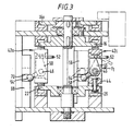
- each blank folding device e. g. device 42 comprises a frame 44 by which the device is attached to the endless chains 20 and 26 and which accommodates a linear series of pivotal folders f1-f5.
- the folders are mounted for pivotal movement independently of each other on a support shaft 46 spanning the length of frame 44 and are axially resiliently loaded by an end spring 48.
- Each folder « f (see « f1 » in Figure 3) comprises an upstanding lug 50 which is rotatably mounted on shaft 46, a blank engaging portion 52 extending in one direction outwardly of the frame at the upper end of the lug and a cam follower 54 extending in the opposite direction outwardly of the frame at the lower end of the lug.
- the blank engaging portion 52 of each folder comprises a pair of pivotal fingers fa and fb.
- FIG. 4 illustrates the upstream end of the folding station « S » in which a carton blank « b » of the wrap-around type is moving along the feed path « F » in synchronism with folder device 42c.
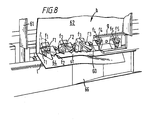
- the blank is formed with a linear series of article heel retaining apertures « r » which are struck along the fold line 60 which foldably connects a side wall panel 62 with a bottom lap panel 64 of the blank.
- Such heel retaining apertures are provided to receive e. g. heel portions of bottles to assist retention of the bottles in the completed carton.
- the heel retaining apertures are each defined in part, by foldable reinforcing tabs t1 and t2 which are frangibly connected together by a small nick before the aperture is opened and which are foldable, to open the aperture, into overlapping relationship with adjacent portions of the side wall and base panel of the blank.
- Blank « b » is shown guided between guide bar « g and guide strip « st » in feed path « F » entering the folding station « S cauliflower
- the blank is engaged by folding device 42c as it moves into the folding station « S » of working path « W Recipe
- Fixed portions « p » of the frame 44 Figure 1) are provided with pegs « pg » ( Figures 4-8) which locate in side wall apertures of the tlank to maintain the blank and folding device fixed as they move through the folding station.
- Articles e. g. bottles to be wrapped are conveyed along the feed path « F adjacent blank « b by feed lugs 61 disposed at spaced locations along upper endless chain 38.
- Each pivotal finger f1a, f1b has a carton engaging end « e » and a transverse shoulder « S remote therefrom including pivot point « p » located within the frame of the folding device.
- the shoulder « S has a back abutment face « sb and a forward abutment face « sf » disposed so as to strike against a back stop surface. « bs and a forward stop surface « fs respectively of the frame.
- the cam follower of folder « f1 rides down cam profile « C5 thereby causing the pivotal fingers of folder « f1 to retract from aperture « r1 » to their initial positions at which the back abutment faces « sb » of the pivotal fingers strike the back stop surfaces « bs causing the pivotal fingers to close.
- the base panel 64 of the blank is guided further towards the horizontal. When folding of the base panel is complete, it will underlie the bases of the articles in a'row of articles conveyed adjacent mechanism 10. Simultaneously, the other base panel of the blank would have been brought into a similar position in relation to a parallel row of articles by a juxtaposed mechanism.
- the folding device 42c When the folding device 42c is transferred through the position of device 42 into the return path « R » it is conveyed through a re-set station « RS as occupied by folding device 42a ( Figure 2).
- the re-set station includes a further cam block 68 ( Figure 3) in which a horizontal straight line cam track 70 is formed.
- the downstream mouth of the cam track 70 is flared to lead in the cam followers of the folders « f gut Thereafter, the folders are reset during movement through the straight line cam track 70 into a position that puts the followers into alignment with the upstream end of cam track 58; that is, positioned for movement into cam profile C1 to repeat the foregoing cycle of operation on the next succeeding blank.
- the fingers when the fingers are pivoted into their extreme outward position, the fingers move apart to engage and fold outwardly the tabs t1 and t2 of a heel retaining aperture « r » and when the fingers are pivoted into their fully retracted position, the fingers are closed together.
Landscapes
- Engineering & Computer Science (AREA)
- Mechanical Engineering (AREA)
- Making Paper Articles (AREA)
- Basic Packing Technique (AREA)
Claims (8)
Applications Claiming Priority (2)
| Application Number | Priority Date | Filing Date | Title |
|---|---|---|---|
| GB8510469 | 1985-04-24 | ||
| GB858510469A GB8510469D0 (en) | 1985-04-24 | 1985-04-24 | Packaging machine |
Publications (3)
| Publication Number | Publication Date |
|---|---|
| EP0200445A2 EP0200445A2 (de) | 1986-11-05 |
| EP0200445A3 EP0200445A3 (en) | 1987-11-19 |
| EP0200445B1 true EP0200445B1 (de) | 1990-03-28 |
Family
ID=10578146
Family Applications (1)
| Application Number | Title | Priority Date | Filing Date |
|---|---|---|---|
| EP19860302965 Expired EP0200445B1 (de) | 1985-04-24 | 1986-04-21 | Verpackungsmaschine |
Country Status (5)
| Country | Link |
|---|---|
| EP (1) | EP0200445B1 (de) |
| JP (1) | JPH0723130B2 (de) |
| DE (1) | DE3669855D1 (de) |
| ES (1) | ES293789Y (de) |
| GB (1) | GB8510469D0 (de) |
Families Citing this family (5)
| Publication number | Priority date | Publication date | Assignee | Title |
|---|---|---|---|---|
| GB8729777D0 (en) * | 1987-12-21 | 1988-02-03 | Mead Corp | Carton flap folding mechanism |
| GB9319970D0 (en) * | 1993-09-24 | 1993-11-17 | Mead Corp | Carton folding mechanism for wraparound cartons |
| US5664401A (en) * | 1993-09-24 | 1997-09-09 | The Mead Corporation | Carton folding mechanism for wraparound cartons |
| EP0708026B1 (de) * | 1994-10-20 | 1999-06-09 | Riverwood International Corporation | Mechanismus zum Aktivieren von Schachteln |
| GB9421189D0 (en) * | 1994-10-20 | 1994-12-07 | Riverwood Int Ltd | Carton activating mechanism |
Family Cites Families (1)
| Publication number | Priority date | Publication date | Assignee | Title |
|---|---|---|---|---|
| US3572003A (en) * | 1968-09-13 | 1971-03-23 | Mead Corp | Packaging machine and method |
-
1985
- 1985-04-24 GB GB858510469A patent/GB8510469D0/en active Pending
-
1986
- 1986-04-21 DE DE8686302965T patent/DE3669855D1/de not_active Expired - Lifetime
- 1986-04-21 EP EP19860302965 patent/EP0200445B1/de not_active Expired
- 1986-04-24 JP JP9585386A patent/JPH0723130B2/ja not_active Expired - Lifetime
- 1986-04-24 ES ES1986293789U patent/ES293789Y/es not_active Expired
Also Published As
| Publication number | Publication date |
|---|---|
| EP0200445A3 (en) | 1987-11-19 |
| ES293789U (es) | 1986-08-01 |
| JPH0723130B2 (ja) | 1995-03-15 |
| GB8510469D0 (en) | 1985-05-30 |
| DE3669855D1 (de) | 1990-05-03 |
| JPS61259907A (ja) | 1986-11-18 |
| ES293789Y (es) | 1987-04-16 |
| EP0200445A2 (de) | 1986-11-05 |
Similar Documents
| Publication | Publication Date | Title |
|---|---|---|
| US3991660A (en) | Carton expander | |
| US5148654A (en) | Packaging system | |
| US5778630A (en) | Carton folding mechanism for wraparound cartons | |
| US3815320A (en) | Wrapping machine | |
| US4023328A (en) | Packaging machine | |
| NZ230566A (en) | High speed packaging of grouped articles in cardboard carton blanks | |
| US3045401A (en) | Machine for packaging articles | |
| US4566248A (en) | Packaging apparatus and method | |
| RU2179943C2 (ru) | Устройство для совместного вытягивания донных панелей транспортировочного средства в машине для загрузки транспортировочных средств | |
| US4012887A (en) | Packaging machine | |
| US4571916A (en) | Secondary packaging machine | |
| ZA877080B (en) | Wrap-around packaging machine | |
| EP0200445B1 (de) | Verpackungsmaschine | |
| AU687102B2 (en) | Carton folding mechanism for wraparound cartons | |
| US3415033A (en) | Packaging machine and method | |
| EP0322159B1 (de) | Faltmechanimus für Kartonklappen | |
| US3295291A (en) | Packaging machine and method | |
| EP0242992B1 (de) | Mechanismus zum Falten eines Kartonzuschnitts | |
| US3220155A (en) | Blank folding apparatus | |
| US4554778A (en) | Packaging machine and method | |
| US4563853A (en) | Packaging machine | |
| EP0092402A2 (de) | Schachtelverpackungsapparat | |
| US3431826A (en) | Machine and method for folding an insert | |
| GB9309915D0 (en) | Carton packing apparatus | |
| EP0645306B1 (de) | Schachtel-Faltvorrichtung für Hüllkartons |
Legal Events
| Date | Code | Title | Description |
|---|---|---|---|
| PUAI | Public reference made under article 153(3) epc to a published international application that has entered the european phase |
Free format text: ORIGINAL CODE: 0009012 |
|
| AK | Designated contracting states |
Kind code of ref document: A2 Designated state(s): BE DE FR GB IT NL |
|
| PUAL | Search report despatched |
Free format text: ORIGINAL CODE: 0009013 |
|
| AK | Designated contracting states |
Kind code of ref document: A3 Designated state(s): BE DE FR GB IT NL |
|
| 17P | Request for examination filed |
Effective date: 19880518 |
|
| 17Q | First examination report despatched |
Effective date: 19890612 |
|
| GRAA | (expected) grant |
Free format text: ORIGINAL CODE: 0009210 |
|
| AK | Designated contracting states |
Kind code of ref document: B1 Designated state(s): BE DE FR GB IT NL |
|
| REF | Corresponds to: |
Ref document number: 3669855 Country of ref document: DE Date of ref document: 19900503 |
|
| ITF | It: translation for a ep patent filed | ||
| ET | Fr: translation filed | ||
| PLBE | No opposition filed within time limit |
Free format text: ORIGINAL CODE: 0009261 |
|
| STAA | Information on the status of an ep patent application or granted ep patent |
Free format text: STATUS: NO OPPOSITION FILED WITHIN TIME LIMIT |
|
| 26N | No opposition filed | ||
| ITTA | It: last paid annual fee | ||
| REG | Reference to a national code |
Ref country code: GB Ref legal event code: IF02 |
|
| PGFP | Annual fee paid to national office [announced via postgrant information from national office to epo] |
Ref country code: FR Payment date: 20020311 Year of fee payment: 17 |
|
| PGFP | Annual fee paid to national office [announced via postgrant information from national office to epo] |
Ref country code: GB Payment date: 20020313 Year of fee payment: 17 |
|
| PGFP | Annual fee paid to national office [announced via postgrant information from national office to epo] |
Ref country code: DE Payment date: 20020314 Year of fee payment: 17 |
|
| PGFP | Annual fee paid to national office [announced via postgrant information from national office to epo] |
Ref country code: NL Payment date: 20020318 Year of fee payment: 17 |
|
| PGFP | Annual fee paid to national office [announced via postgrant information from national office to epo] |
Ref country code: BE Payment date: 20020417 Year of fee payment: 17 |
|
| PG25 | Lapsed in a contracting state [announced via postgrant information from national office to epo] |
Ref country code: GB Free format text: LAPSE BECAUSE OF NON-PAYMENT OF DUE FEES Effective date: 20030421 |
|
| PG25 | Lapsed in a contracting state [announced via postgrant information from national office to epo] |
Ref country code: BE Free format text: LAPSE BECAUSE OF NON-PAYMENT OF DUE FEES Effective date: 20030430 |
|
| BERE | Be: lapsed |
Owner name: THE *MEAD CORP. Effective date: 20030430 |
|
| PG25 | Lapsed in a contracting state [announced via postgrant information from national office to epo] |
Ref country code: NL Free format text: LAPSE BECAUSE OF NON-PAYMENT OF DUE FEES Effective date: 20031101 Ref country code: DE Free format text: LAPSE BECAUSE OF NON-PAYMENT OF DUE FEES Effective date: 20031101 |
|
| NLV4 | Nl: lapsed or anulled due to non-payment of the annual fee |
Effective date: 20031101 |
|
| GBPC | Gb: european patent ceased through non-payment of renewal fee |
Effective date: 20030421 |
|
| PG25 | Lapsed in a contracting state [announced via postgrant information from national office to epo] |
Ref country code: FR Free format text: LAPSE BECAUSE OF NON-PAYMENT OF DUE FEES Effective date: 20031231 |
|
| REG | Reference to a national code |
Ref country code: FR Ref legal event code: ST |
|
| REG | Reference to a national code |
Ref country code: FR Ref legal event code: TP |
|
| PG25 | Lapsed in a contracting state [announced via postgrant information from national office to epo] |
Ref country code: IT Free format text: LAPSE BECAUSE OF NON-PAYMENT OF DUE FEES Effective date: 20050421 |
|
| REG | Reference to a national code |
Ref country code: FR Ref legal event code: CL |