EP0200538B1 - Appareil de commande de débit de fluide - Google Patents
Appareil de commande de débit de fluide Download PDFInfo
- Publication number
- EP0200538B1 EP0200538B1 EP86303267A EP86303267A EP0200538B1 EP 0200538 B1 EP0200538 B1 EP 0200538B1 EP 86303267 A EP86303267 A EP 86303267A EP 86303267 A EP86303267 A EP 86303267A EP 0200538 B1 EP0200538 B1 EP 0200538B1
- Authority
- EP
- European Patent Office
- Prior art keywords
- pressure
- fluid flow
- responsive element
- flow control
- governor
- Prior art date
- Legal status (The legal status is an assumption and is not a legal conclusion. Google has not performed a legal analysis and makes no representation as to the accuracy of the status listed.)
- Expired - Lifetime
Links
- 239000012530 fluid Substances 0.000 title claims description 75
- 238000011144 upstream manufacturing Methods 0.000 claims description 18
- 238000006073 displacement reaction Methods 0.000 claims description 14
- 230000006835 compression Effects 0.000 claims description 8
- 238000007906 compression Methods 0.000 claims description 8
- 230000007935 neutral effect Effects 0.000 claims description 6
- XLYOFNOQVPJJNP-UHFFFAOYSA-N water Substances O XLYOFNOQVPJJNP-UHFFFAOYSA-N 0.000 description 22
- 238000010079 rubber tapping Methods 0.000 description 8
- 239000002699 waste material Substances 0.000 description 5
- 230000000694 effects Effects 0.000 description 4
- 230000001419 dependent effect Effects 0.000 description 3
- 210000004907 gland Anatomy 0.000 description 3
- 230000000295 complement effect Effects 0.000 description 1
- 150000001875 compounds Chemical class 0.000 description 1
- 238000010276 construction Methods 0.000 description 1
- 230000003111 delayed effect Effects 0.000 description 1
- 238000011835 investigation Methods 0.000 description 1
- 239000002184 metal Substances 0.000 description 1
- 230000004048 modification Effects 0.000 description 1
- 238000012986 modification Methods 0.000 description 1
- 238000012544 monitoring process Methods 0.000 description 1
- 238000003825 pressing Methods 0.000 description 1
- 238000011084 recovery Methods 0.000 description 1
- 239000012858 resilient material Substances 0.000 description 1
- 230000000717 retained effect Effects 0.000 description 1
Images


Classifications
-
- G—PHYSICS
- G05—CONTROLLING; REGULATING
- G05D—SYSTEMS FOR CONTROLLING OR REGULATING NON-ELECTRIC VARIABLES
- G05D7/00—Control of flow
- G05D7/03—Control of flow with auxiliary non-electric power
-
- Y—GENERAL TAGGING OF NEW TECHNOLOGICAL DEVELOPMENTS; GENERAL TAGGING OF CROSS-SECTIONAL TECHNOLOGIES SPANNING OVER SEVERAL SECTIONS OF THE IPC; TECHNICAL SUBJECTS COVERED BY FORMER USPC CROSS-REFERENCE ART COLLECTIONS [XRACs] AND DIGESTS
- Y10—TECHNICAL SUBJECTS COVERED BY FORMER USPC
- Y10T—TECHNICAL SUBJECTS COVERED BY FORMER US CLASSIFICATION
- Y10T137/00—Fluid handling
- Y10T137/7722—Line condition change responsive valves
- Y10T137/7758—Pilot or servo controlled
- Y10T137/7759—Responsive to change in rate of fluid flow
-
- Y—GENERAL TAGGING OF NEW TECHNOLOGICAL DEVELOPMENTS; GENERAL TAGGING OF CROSS-SECTIONAL TECHNOLOGIES SPANNING OVER SEVERAL SECTIONS OF THE IPC; TECHNICAL SUBJECTS COVERED BY FORMER USPC CROSS-REFERENCE ART COLLECTIONS [XRACs] AND DIGESTS
- Y10—TECHNICAL SUBJECTS COVERED BY FORMER USPC
- Y10T—TECHNICAL SUBJECTS COVERED BY FORMER US CLASSIFICATION
- Y10T137/00—Fluid handling
- Y10T137/8593—Systems
- Y10T137/86493—Multi-way valve unit
- Y10T137/86574—Supply and exhaust
- Y10T137/86622—Motor-operated
- Y10T137/8663—Fluid motor
-
- Y—GENERAL TAGGING OF NEW TECHNOLOGICAL DEVELOPMENTS; GENERAL TAGGING OF CROSS-SECTIONAL TECHNOLOGIES SPANNING OVER SEVERAL SECTIONS OF THE IPC; TECHNICAL SUBJECTS COVERED BY FORMER USPC CROSS-REFERENCE ART COLLECTIONS [XRACs] AND DIGESTS
- Y10—TECHNICAL SUBJECTS COVERED BY FORMER USPC
- Y10T—TECHNICAL SUBJECTS COVERED BY FORMER US CLASSIFICATION
- Y10T137/00—Fluid handling
- Y10T137/8593—Systems
- Y10T137/87169—Supply and exhaust
- Y10T137/87217—Motor
- Y10T137/87225—Fluid motor
Definitions
- This invention relates to fluid flow control apparatus for compressible or incompressible fluids including a fluid flow governor, particularly, though not exclusively, for use in controlling the pressure at an entry point to a distribution system or sub-system for water, for example.
- the present invention consists in fluid flow control apparatus, for controlling the flow of fluid through a pipe, comprising a fluid flow governor; in the pipe, a fluid flow control valve the extent of the opening of which is solely determined by the governor and producing, in operation, a control pressure at a predetermined location in the pipe downstream of the valve; and means for producing, in operation, a differential pressure derived from a characteristic of fluid flow in the pipe, the fluid flow governor comprising a first pressure-responsive element to which the differential pressure is applied and moveable in response to said differential pressure, and a second pressure-responsive element to which a pressure related to the control pressure is applied, means being provided for loading the second pressure-responsive element so as to act thereon in opposition to the fluid pressure on it, characterised in that the second pressure responsive element is acted on by the control pressure and is movable relative to the first pressure-responsive element, that spring means, separate from said locking means, are always connected to the first pressure-responsive element so as to act thereon in opposition to the differential pressure, and means are provided to add together the respective independent
- the governor may be coupled directly to the fluid flow control valve which will then be of a kind in which the extent of valve opening is varied by the governor.
- the governor may be indirectly coupled to the fluid flow control valve by servo means which may comprise, as the element to which the governor is to be directly coupled, a pilot valve in a hydraulic or pneumatic servo system, or a switch in an electrical servo system.
- the characteristic of fluid flow from which the differential pressure is derived may be the rate of fluid flow through the pipe.
- the fluid flow control apparatus may alternatively be intended to serve as a sensitive pressure reducing valve.
- the characteristic of fluid flow from which the differential pressure is derived may then be the rate of change of fluid pressure at a specified region in the pipe.
- the means for producing the differential pressure comprises a device producing (in operation) a pressure which is lower than a pressure upstream of the device (the higher pressure), the difference between the higher pressure and the lower pressure being the differential pressure.
- the said device may be an orifice plate in the pipe, the higher pressure being that upstream of the orifice plate and the lower pressure that in the region of the throat of the orifice plate.
- the higher pressure and the lower pressure may be applied to opposed areas of the first pressure-responsive element, the resultant fluid pressure acting on the first pressure-responsive element being the differential pressure.
- the means for producing the differential pressure may comprise two impulse connections, one to each of opposed areas of the first pressure-responsive element, from the specified region of the pipe, one of the impulse connections including restricting means for producing at the first pressure-responsive element on change of pressure at the region (in operation), a pressure which is lower than the pressure (the higher pressure) in the other impulse connection, the difference between the higher pressure and the lower pressure being the differential pressure.
- the fluid flow control apparatus may include an impulse connection including a throttling device through which fluid pressure is applied to the first pressure-responsive element.
- the fluid pressure affected by the throttled impulse connection may be one of the components of the differential pressure.
- the restriction imposed by the throttling device affects the speed of response to changes in the characteristic of fluid flow, preferably without affecting the speed of response to changes in the control pressure.
- the throttling device may be adjustable; a needle valve, for example.
- the invention further consists in a fluid flow governor for use in fluid flow control apparatus for controlling the flow of fluid through a pipe which includes a fluid flow control valve which the governor is adapted to control and means in the pipe for producing, in operation, a differential pressure derived from a characteristic of fluid flow in the pipe, the governor comprising a first pressure-responsive element moveable in response to an applied differential pressure, and a second pressure-responsive element, means being provided for loading the second pressure-responsive element, and means being provided for enabling a pressure related to control pressure to be applied to the second pressure-responsive element in opposition to the loading thereon, characterised in that the second pressure responsive element is movable relative to the first pressure-responsive element, that spring means for biassing, separate from said loading means, are provided and always connected to the first pressure-responsive element so as to act thereon in opposition to the differential pressure, means are provided for enabling the differential pressure to be applied to the first pressure-responsive element in opposition to the spring means, and means are provided to add together the respective independent displacements of the two pressure-responsive elements and so
- the displacements of the two pressure-responsive elements may be combined at actuating means coupled to the fluid flow control valve or to servo means for actuating the fluid flow control valve.
- the first pressure-responsive element is operatively coupled to the actuating means and the second pressure-responsive element is operatively coupled to the first pressure-responsive element through the spring means, the first and second pressure-responsive elements being open to a first chamber in the sense that in operation forces on the pressure-responsive elements due to pressure in the first chamber oppose the spring means, the first pressure-responsive element being open to a second chamber in the sense that, in operation, the first pressure-responsive element is subjected to the differential pressure resulting from the difference in pressures in the first and second chambers, and the second pressure-responsive element being loaded in the sense to oppose, in operation, pressure applied to the second pressure-responsive element in the first chamber.
- the higher pressure acting on the second pressure-responsive element controls directly or indirectly movement of the fluid-flow control valve to correct the governed pressure.
- the first pressure-responsive element is subjected to the difference between the higher pressure and the lower pressure.
- the deflection of the spring means is dependent upon this pressure difference and alters the relative positions of the first and second pressure-responsive elements and therefore affects the fluid-flow control valve through the actuating means which is directly coupled to the first pressure-responsive element to modify the governed pressure in accordance with this pressure difference.
- the pressure difference depends on the rate offlowthrough the main or pipe and the governed pressure is thus flow compensated.
- the displacements of the two pressure-responsive elements may be combined at fluid flow valve means having first and second relatively movable elements which co-operate to define a closed or neutral position, the first pressure-responsive elements being operatively connected to the first relatively movable elements and the second pressure-responsive element being operatively connected to the second relatively movable elements.
- the relatively movable elements may be a valve body and a valve member movable therein.
- the first and second pressure-responsive elements are preferably of equal effective area.
- a preferred form of pressure-responsive element is a flexible diaphragm but any other suitable known type of pressure-responsive element may be used such as a piston and cylinder or a bellows.
- the second pressure-responsive element may be a diaphragm and the first pressure-responsive element a bellows open at one end, the open end being connected to a movable part of the diaphragm so thatthe bellows is free to move relative to a housing of the governor.
- the diaphragm covers the open end and the first chamber is the interior space defined by the diaphragm and the internal surface of the bellows, the bellows being provided with means for applying pressure to the interior space.
- the second chamber surrounds the bellows.
- the bellows may be made of spring metal or other resilient material. The inherent resilience of the bellows may then enable the bellows to serve as, or at least complement, the spring means.
- the spring means could be an air spring but is conveniently a coil spring with open coils normally loaded in tension but stiff enough and with its end coils stably supported so as to be capable, when required, of transmitting a compressive load, in the manner of a strut.
- the second pressure-responsive element may be loaded by a compression spring.
- the stiffness of the compression spring is greater than that of the spring means, preferably within the range of two to eight times, for example four times, the stiffness of the latter. The greater the ratio of the stiffness of the compression spring to that of the spring means, the greater the effect of the difference in pressures in the first and second chambers on the displacement of the actuating means of the governor.
- the governor of Figure 1 has a housing 1 comprising a body portion 2, a top cover 3 and a bottom cover 4. Between the body portion 2 and the bottom cover 4 a first flexible, diaphragm 5 is clamped and between the body portion 2 and the top cover 3 a second flexible diaphragm 6 is clamped.
- the first and second diaphragms which are of equal effective area, are coupled by a tension spring 7.
- the tension spring 7 is open- coiled but is sufficiently stiff to be able, if required, to transmit a compressive load.
- the end coils of the spring 7 are rigidly anchored to their associated diaphragms.
- the second diaphragm 6 is loaded by a compression spring 8 housed in a turret portion 9 of the top cover 3.
- the loading of the spring 8 on the second diaphragm is variable by means of an adjusting screw 10.
- the first diaphragm 5 is secured to a stem 11 which passes out of the bottom cover 4 through a gland 12 and is connected, in this example, to a slidable valve member 13 of a pilot valve 14 of a servo-system for operating a fluid flow control valve to be described later.
- the stem 11 constitutes actuating means by which the governor exerts its control.
- the diaphragms divide the interior of the housing 1 into three chambers, an intermediate chamber 16 (constituting a first chamber) between the two diaphragms which is open to a first impulse pipe 17 including a needle valve 18, a lower chamber 19, (constituting a second chamber) below the first diaphragm 5 and open to a second impulse pipe 20 and an upper chamber 15 above the second diaphragm 6 which is vented to atmosphere.
- valve member 13 is slidable in a valve chamber 21 in a body 22 of the pilot valve 14. From the chamber 21 open three ports 23, 24, 25 which in the intermediate position of the valve member 13 shown in Figure 1 are isolated one from another. Upward movement of the stem 11 from the intermediate position shown connects ports 23 and 24, downward movement connects ports 24 and 25.
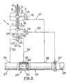
- the reference 26 indicates the water main which is connected at one end 27, the upstream end, to a supply of water under pressure.
- the downstream end 28 of the main 26 leads to the distribution pipes of the district being served.
- the pipe includes a flow control valve 29, in this instance a fluid-pressure controlled valve manufactured by M.I.L. Limited and known as the INBAL valve which comprises a valve housing 30, an ovoid core 31 and a resilient sleeve 32 surrounding the core 31 and sealed at both ends to the valve housing 30, forming an annular control chamber 33 between the sleeve 32 and the wall of the housing 30.
- control chamber 33 If the control chamber 33 is open to atmosphere, pressure at the upstream end 27 of the main will cause the sleeve 32 to move away from the core 31 against the wall of the valve housing 30 as shown in broken lines in Figure 2.
- the main 26 Downstream of the flow control valve 29 the main 26 is provided with an orifice plate 37 the throat of which is connected to the second impulse pipe 20. A tapping 38 between the flow control valve 29 and the orifice plate 37 is connected to the first impulse pipe 17.
- water pressure upstream of the orifice plate (higher pressure) is supplied through the first impulse pipe 17 to the intermediate chamber 16 and applied to the upper side of the first diaphragm 5 and the underside of the second diaphragm 6.
- Pressure at the orifice plate throat tapping (lower pressure) is supplied through the second impulse pipe 20 to the lower chamber and applied to the underside of the first diaphragm 5 which is thus subject to the difference in pressures at the orifice throat and upstream of the orifice. At very low flows in the main 26 this differential pressure is insignificant and has no effect on the first diaphragm 5.
- the pressure upstream of the orifice plate on the second diaphragm 6 exerts an upward force on the second diaphragm which moves upwards until this upward force and downward force due to compression of the spring 8 are equal.
- the tension spring 7 remains at its natural length, moves bodily upwards with the second diaphragm 6 and causes the first diaphragm 5 to follow the movement of the second diaphragm.
- the resulting upward movement of the stem 11 and valve member 13 connects ports 23 and 24 applying main pressure from upstream of the control valve 29 to the control chamber 33 and begins to close the control valve 29 to reduce the control pressure in the main 26 upstream of the orifice plate 37 until the reduction in pressure on the underside of the second diaphragm 6 and its resulting downward movement is sufficient to return the valve member 13 to the mid-position.
- the governor acts simply as a normal pressure governor monitoring and maintaining the required control pressure at the location of the tapping 38 upstream of the orifice plate 37.
- the entry to the water distribution system may be regarded as a point sufficiently far downstream of the orifice plate 37 for velocity head at the throat of the orifice plate to have been recovered.
- the governed pressure that is to say, the pressure required at such an entry point is in this instance directly dependent upon the control pressure at the location of the tapping 38. Varying the governed pressure at the entry to the distribution system in proportion to the differential pressure at an orifice plate will enable a satisfactory delivery pressure to be maintained at the far end of the distribution system with varying flows.
- the facility this provides of enabling the governed pressure to be reduced substantially when the demand for water is low, for example at night, is particularly useful in avoiding waste of water at leaks in the distribution system.
- the needle valve 18 is provided to enable the response of the governor to changes in flow to be delayed. Its effect may be understood by considering the following situation.
- the effect of opening the needle valve very slightly will be to allow water to flow into or out of the intermediate chamber 16 very slowly in response to changes in the differential pressure in the impulse pipes 17 and 20 that is to say the difference between the higher pressure upstream of the orifice plate 37 and the lower pressure at the throat which is dependent on the rate of flow through the main 26.
- the response to pressure will continue to be rapid.
- a compound spring may be provided so that the amount of compensation for change of flow will be something other than a direct proportion of orifice plate differential.
- the range of compensation can be limited to a fixed value.
- the system would continue to operate as a pressure reducing valve responsive to changes in pressure upstream of the orifice plate 37, but further increases in orifice plate differential would not raise the control pressure which the system was aiming to achieve.
- a fluid flow governor according to the invention may serve as a very sensitive pressure reducing valve without flow compensation.
- the pressures applied to the first or intermediate chamber 16 and the second or lower chamber 19 are taken from the same point but through separate impulse pipes 17 and 20 as previously described, the impulse pipe 17 including the needle valve 18 adjusted to be very nearly closed.
- the differential pressure on the diaphragm 5 becomes less so that the control pressure is again mainly under the control of the diaphragm 6.
- the governor can thus provide a pressure reducing valve capable of responding rapidly to control pressure fluctuations with less tendency to hunt than conventional sensitive pressure reducing valves.
- a body portion 2' of the housing comprises an upturned cup portion 40 and an inverted cup portion 41 rigidly secured together, for example, by stays 42.
- the top cover 3 is similar to the top cover in Figure 1.
- a bottom cover 4' is similar to the top cover 3.
- the first diaphragm 5 is clamped between the cup portion 41 and the bottom cover 4' and the second diaphragm 6 is clamped between the cup portion 40 and the top cover 3.
- the stem 11 connected to the valve member 13 of the pilot valve 14 is in the embodiment, connected directly to the second diaphragm 6 and passes out of the housing through a gland 43 in the cup portion 40.
- a rod 44 connected to the first diaphragm 5 extends upwards through a gland 45 in the cup portion 41 and is secured to the body 22 of the valve 14 which, in this embodiment is free to move relative to the housing 1, pipe connections to its ports 23, 24 and 25 being made by flexible hoses (not shown).
- the spring means 7, which is similar to the spring means 7 of Figure 1 except that it need not be capable of transmitting a compressive load, is housed in a turret portion 53 of the bottom cover 4 and is anchored to a cap 54 at the lower end of the turret portion 4'.
- the cap 54 is preferably adjustably mounted on the turret portion 53 to enable the tension of the spring means 7 to be varied.
- the upper chamber 15 above the second diaphragm 6 is vented to atmosphere as in the embodiment of Figure 1.
- a chamber 46 formed by the interior of the cup portion 40 and the second diaphragm 6 is connected by an impulse pipe 47 to a location in a main or pipe at which a control pressure is to be monitored.
- a chamber 48 formed by the interior of the cup portion 41 and the first diaphragm 5 is open to an impulse pipe 49.
- a chamber 50 formed by the bottom cover 4 and the first diaphragm 5 is open to an impulse pipe 51 which includes a needle valve 52 for imposing an adjustable restriction in the impulse pipe 51.
- the impulse pipes 49 and 51 are connected to the means for producing the differential pressure, impulse pipe 49 to the lower pressure component and impulse pipe 51 to the higher pressure.
- the needle valve 52 enables the rate to be varied at which the governor responds to changes in differential pressure.
- the impulse pipes 47, 49 and 51 may be connected independently of one another and as described above.
- the means for producing the differential pressure need not be at the location at which pressure is being monitored by the impulse pipe 47.
- the orifice plate 37 could be in a region of the pipe upstream of the flow control valve 29. It will generally be convenient to use as one of the component pressures of the differential pressure the control pressure at the location at which pressure is being monitored and then the impulse pipe 47 can be combined with one of the other impulse pipes 49, 51.
- impulse pipe 47 would be combined with the impulse pipe 51 and connected to the tapping 38 in Figure 2, the impulse pipe 49 being connected to the throat of the orifice plate 37.
- Control pressure is still directly applied to the diaphragm 6 to compress its loading spring 8 but the diaphragm now moves the valve member 13 directly.
- the neutral position of the valve 14 is altered by moving the body 22 of the valve 14 relative to the valve member 13. The movement of the valve body by the diaphragm 5 depends on rate of flow and the spring rate of the spring means 7.
- control pressure being monitored and kept constant under given flow conditions is the governed pressure, that is to say the pressure required, for example, at the entry to the distribution system downstream of the orifice plate to meet distribution needs.
- the lower pressure component of the differential pressure is used as the control pressure. This may be done by combining the impulse pipe 47 with the impulse pipe 49. If, for example, this combined connection is made to the throat of the orifice plate 37 in Figure 2, the governed pressure is not directly proportional to the control pressure but, though equal to it at very low flows, becomes higher than the control pressure at high flows because of the recovery of velocity head well downstream of the orifice plate 37. Greater compensation for rate of flow may be obtained by such an arrangement and may be advantageous in some circumstances.
- the governor of Figure 3 may also be used as a very sensitive pressure reducing valve as described in connection with the governor of Figure 1, the impulse pipes 49 and 51 both being connected to the same region of the main or pipe, the restriction imposed by needle valve 52 producing a differential pressure when pressure in the said region of the main or pipe changes.
- the characteristic of fluid flow from which the differential pressure is derived is thus the rate of change of pressure at the said region of the main or pipe.
Landscapes
- Engineering & Computer Science (AREA)
- Power Engineering (AREA)
- Physics & Mathematics (AREA)
- General Physics & Mathematics (AREA)
- Automation & Control Theory (AREA)
- Control Of Fluid Pressure (AREA)
- Safety Valves (AREA)
- Flow Control (AREA)
Claims (12)
Applications Claiming Priority (2)
| Application Number | Priority Date | Filing Date | Title |
|---|---|---|---|
| GB8511146 | 1985-05-02 | ||
| GB858511146A GB8511146D0 (en) | 1985-05-02 | 1985-05-02 | Fluid flow governor |
Publications (3)
| Publication Number | Publication Date |
|---|---|
| EP0200538A2 EP0200538A2 (fr) | 1986-11-05 |
| EP0200538A3 EP0200538A3 (en) | 1987-10-07 |
| EP0200538B1 true EP0200538B1 (fr) | 1990-08-16 |
Family
ID=10578540
Family Applications (1)
| Application Number | Title | Priority Date | Filing Date |
|---|---|---|---|
| EP86303267A Expired - Lifetime EP0200538B1 (fr) | 1985-05-02 | 1986-04-30 | Appareil de commande de débit de fluide |
Country Status (6)
| Country | Link |
|---|---|
| US (1) | US4697616A (fr) |
| EP (1) | EP0200538B1 (fr) |
| JP (1) | JPS62118169A (fr) |
| DE (1) | DE3673447D1 (fr) |
| GB (1) | GB8511146D0 (fr) |
| IL (1) | IL78664A (fr) |
Cited By (1)
| Publication number | Priority date | Publication date | Assignee | Title |
|---|---|---|---|---|
| CN104265964A (zh) * | 2014-09-12 | 2015-01-07 | 诸文伟 | 一种天然气曲流式调压器 |
Families Citing this family (15)
| Publication number | Priority date | Publication date | Assignee | Title |
|---|---|---|---|---|
| US4969364A (en) * | 1986-12-08 | 1990-11-13 | Daikin Industries, Ltd. | Flowmeter |
| AT389393B (de) * | 1987-10-02 | 1989-11-27 | Bock Orthopaed Ind | Regelventil |
| SE8801519L (sv) * | 1988-04-22 | 1989-10-23 | Cementa Mineral Ab | Anordning foer reglering av floedet av troegflytande fluider |
| US5351705A (en) * | 1992-08-26 | 1994-10-04 | Watertronics, Inc. | Method and apparatus for controlling fluid pumps and valves to regulate fluid pressure and to eliminate fluid flow surges |
| FR2718858B1 (fr) * | 1994-04-14 | 1996-07-19 | Bayard | Dispositif de modulation de la pression de la vanne de base d'un réseau de distribution de fluide en fonction du débit aval . |
| US5671774A (en) * | 1996-06-18 | 1997-09-30 | Nelson Irrigation Corporation | Rate-of-flow control valve |
| US5967176A (en) * | 1998-04-17 | 1999-10-19 | Blann; Brian David Francis | Automatic flow control valve with variable set-points |
| GB0208840D0 (en) * | 2002-04-18 | 2002-05-29 | Novamedix Distrib Ltd | Fluid control valve |
| JP3583123B1 (ja) * | 2004-01-06 | 2004-10-27 | 株式会社東京フローメータ研究所 | 流量制御弁及び流量制御装置 |
| US8091582B2 (en) | 2007-04-13 | 2012-01-10 | Cla-Val Co. | System and method for hydraulically managing fluid pressure downstream from a main valve between set points |
| US20080251130A1 (en) * | 2007-04-13 | 2008-10-16 | Cla-Val Co. | System and method for hydraulically managing fluid pressure downstream from a main valve |
| US20100071787A1 (en) * | 2007-10-29 | 2010-03-25 | Cla-Val Co. | System, including a variable orifice assembly, for hydraulically managing pressure in a fluid distribution system between pressure set points |
| US20190145538A1 (en) * | 2017-11-14 | 2019-05-16 | Sur-Flo Meters & Controls Ltd | Valve with Expandable Sleeve Fitted Over Perforated Walls of Inlet and Outlet Channels to Control Flow Therebetween |
| CN109630732B (zh) * | 2019-01-30 | 2024-02-27 | 余姚市三顺净水科技有限公司 | 压力开关阀 |
| CN114484026B (zh) * | 2022-04-06 | 2022-07-01 | 艾肯(江苏)工业技术有限公司 | 一种带有压力可调的先导隔膜式减压阀 |
Family Cites Families (9)
| Publication number | Priority date | Publication date | Assignee | Title |
|---|---|---|---|---|
| US2230914A (en) * | 1938-08-15 | 1941-02-04 | Gayle C Sherman | Pressure booster |
| US2291731A (en) * | 1940-01-03 | 1942-08-04 | Milton E Lake | Pressure regulating system |
| US2385664A (en) * | 1941-08-19 | 1945-09-25 | Gen Electric | Cabin supercharger arrangements |
| GB684554A (en) * | 1945-04-23 | 1952-12-17 | Garrett Corp | Improvements in means for regulating the flow of fluid into an enclosure |
| US2627703A (en) * | 1948-05-13 | 1953-02-10 | Theodore N Spencer | Flow responsive pressure regulator |
| US2650607A (en) * | 1949-02-23 | 1953-09-01 | M & J Engineering Co | Gas flow control apparatus |
| CH288875A (de) * | 1949-04-11 | 1953-02-15 | Bernhard Holm Carl | Einrichtung mit einem Membranventil zur Regelung des Durchflusses von Flüssigkeit. |
| US3221764A (en) * | 1961-10-09 | 1965-12-07 | Parker Hannifin Corp | Excess flow controlled shut-off for pilot controlled regulator |
| US3525355A (en) * | 1967-10-13 | 1970-08-25 | Robertshaw Controls Co | Flow control apparatus |
-
1985
- 1985-05-02 GB GB858511146A patent/GB8511146D0/en active Pending
-
1986
- 1986-04-30 US US06/858,220 patent/US4697616A/en not_active Expired - Fee Related
- 1986-04-30 DE DE8686303267T patent/DE3673447D1/de not_active Expired - Lifetime
- 1986-04-30 EP EP86303267A patent/EP0200538B1/fr not_active Expired - Lifetime
- 1986-05-02 IL IL78664A patent/IL78664A/xx not_active IP Right Cessation
- 1986-05-02 JP JP61101276A patent/JPS62118169A/ja active Pending
Cited By (1)
| Publication number | Priority date | Publication date | Assignee | Title |
|---|---|---|---|---|
| CN104265964A (zh) * | 2014-09-12 | 2015-01-07 | 诸文伟 | 一种天然气曲流式调压器 |
Also Published As
| Publication number | Publication date |
|---|---|
| IL78664A0 (en) | 1986-08-31 |
| EP0200538A3 (en) | 1987-10-07 |
| DE3673447D1 (de) | 1990-09-20 |
| GB8511146D0 (en) | 1985-06-12 |
| US4697616A (en) | 1987-10-06 |
| JPS62118169A (ja) | 1987-05-29 |
| EP0200538A2 (fr) | 1986-11-05 |
| IL78664A (en) | 1991-11-21 |
Similar Documents
| Publication | Publication Date | Title |
|---|---|---|
| EP0200538B1 (fr) | Appareil de commande de débit de fluide | |
| US5967176A (en) | Automatic flow control valve with variable set-points | |
| US4617958A (en) | Control valve | |
| US6263905B1 (en) | Automatic regulating valve apparatus | |
| US1925301A (en) | Valve | |
| US4565209A (en) | Pressure regulating valve with feedback control | |
| US3450152A (en) | Fluid pressure operated proportioning transmitter and controller | |
| US2163597A (en) | Fluid flow regulator | |
| US4106824A (en) | Hydrostatic supporting device | |
| US3425442A (en) | Pressure regulator | |
| US2637301A (en) | Air actuated power cylinder control with rate response | |
| GB2176316A (en) | Fluid flow control apparatus | |
| US4253603A (en) | Temperature responsive control apparatus | |
| KR830008060A (ko) | 유압식 제어 시스템 | |
| US4253484A (en) | Valve operator | |
| US2149390A (en) | Pressure regulating device | |
| US4263838A (en) | Pneumatic positioner | |
| CA1270176A (fr) | Distributeur regulateur de debit, a compensation | |
| US4852850A (en) | Valve system with adjustable seating force | |
| US1772403A (en) | Regulator | |
| US4264035A (en) | Dual reset controller | |
| US2277162A (en) | Pressure regulator | |
| US2176603A (en) | Self-stabilizing control mechanism | |
| US3794062A (en) | Fluid pressure reducing valve | |
| US2301301A (en) | Air operated instrument |
Legal Events
| Date | Code | Title | Description |
|---|---|---|---|
| PUAI | Public reference made under article 153(3) epc to a published international application that has entered the european phase |
Free format text: ORIGINAL CODE: 0009012 |
|
| AK | Designated contracting states |
Kind code of ref document: A2 Designated state(s): DE FR GB IT |
|
| PUAL | Search report despatched |
Free format text: ORIGINAL CODE: 0009013 |
|
| AK | Designated contracting states |
Kind code of ref document: A3 Designated state(s): DE FR GB IT |
|
| 17P | Request for examination filed |
Effective date: 19880118 |
|
| 17Q | First examination report despatched |
Effective date: 19890417 |
|
| GRAA | (expected) grant |
Free format text: ORIGINAL CODE: 0009210 |
|
| RBV | Designated contracting states (corrected) |
Designated state(s): DE FR IT |
|
| AK | Designated contracting states |
Kind code of ref document: B1 Designated state(s): DE FR IT |
|
| REF | Corresponds to: |
Ref document number: 3673447 Country of ref document: DE Date of ref document: 19900920 |
|
| ET | Fr: translation filed | ||
| ITF | It: translation for a ep patent filed | ||
| ITTA | It: last paid annual fee | ||
| PLBE | No opposition filed within time limit |
Free format text: ORIGINAL CODE: 0009261 |
|
| STAA | Information on the status of an ep patent application or granted ep patent |
Free format text: STATUS: NO OPPOSITION FILED WITHIN TIME LIMIT |
|
| 26N | No opposition filed | ||
| ITPR | It: changes in ownership of a european patent |
Owner name: CESSIONE;BRITISH TECHNOLOGY GROUP LIMITED |
|
| REG | Reference to a national code |
Ref country code: FR Ref legal event code: TP |
|
| PGFP | Annual fee paid to national office [announced via postgrant information from national office to epo] |
Ref country code: FR Payment date: 19930405 Year of fee payment: 8 |
|
| PGFP | Annual fee paid to national office [announced via postgrant information from national office to epo] |
Ref country code: DE Payment date: 19930621 Year of fee payment: 8 |
|
| PG25 | Lapsed in a contracting state [announced via postgrant information from national office to epo] |
Ref country code: FR Effective date: 19941229 |
|
| PG25 | Lapsed in a contracting state [announced via postgrant information from national office to epo] |
Ref country code: DE Effective date: 19950103 |
|
| REG | Reference to a national code |
Ref country code: FR Ref legal event code: ST |
|
| PG25 | Lapsed in a contracting state [announced via postgrant information from national office to epo] |
Ref country code: IT Free format text: LAPSE BECAUSE OF NON-PAYMENT OF DUE FEES;WARNING: LAPSES OF ITALIAN PATENTS WITH EFFECTIVE DATE BEFORE 2007 MAY HAVE OCCURRED AT ANY TIME BEFORE 2007. THE CORRECT EFFECTIVE DATE MAY BE DIFFERENT FROM THE ONE RECORDED. Effective date: 20050430 |