EP0200619A1 - Einrichtung zum Messen des Niveaus von in einem Behälter enthaltenem elektrisch leitendem Material und ihre Anwendungen - Google Patents
Einrichtung zum Messen des Niveaus von in einem Behälter enthaltenem elektrisch leitendem Material und ihre Anwendungen Download PDFInfo
- Publication number
- EP0200619A1 EP0200619A1 EP86400771A EP86400771A EP0200619A1 EP 0200619 A1 EP0200619 A1 EP 0200619A1 EP 86400771 A EP86400771 A EP 86400771A EP 86400771 A EP86400771 A EP 86400771A EP 0200619 A1 EP0200619 A1 EP 0200619A1
- Authority
- EP
- European Patent Office
- Prior art keywords
- level
- winding
- windings
- extreme
- measuring
- Prior art date
- Legal status (The legal status is an assumption and is not a legal conclusion. Google has not performed a legal analysis and makes no representation as to the accuracy of the status listed.)
- Granted
Links
Images

Classifications
-
- G—PHYSICS
- G01—MEASURING; TESTING
- G01F—MEASURING VOLUME, VOLUME FLOW, MASS FLOW OR LIQUID LEVEL; METERING BY VOLUME
- G01F23/00—Indicating or measuring liquid level or level of fluent solid material, e.g. indicating in terms of volume or indicating by means of an alarm
- G01F23/22—Indicating or measuring liquid level or level of fluent solid material, e.g. indicating in terms of volume or indicating by means of an alarm by measuring physical variables, other than linear dimensions, pressure or weight, dependent on the level to be measured, e.g. by difference of heat transfer of steam or water
- G01F23/26—Indicating or measuring liquid level or level of fluent solid material, e.g. indicating in terms of volume or indicating by means of an alarm by measuring physical variables, other than linear dimensions, pressure or weight, dependent on the level to be measured, e.g. by difference of heat transfer of steam or water by measuring variations of capacity or inductance of capacitors or inductors arising from the presence of liquid or fluent solid material in the electric or electromagnetic fields
Definitions
- the invention relates to a device for measuring the level of an electrically conductive medium contained in an envelope, the upper level of which can move between two extreme positions inside this envelope.
- probes comprising two electrical coils wound on a support itself fixed relative to the envelope containing the electrically conductive medium whose level is measured.
- One of the windings or primary winding is supplied with alternating electric current and the voltage induced in the second winding, or secondary winding, is measured, this induced voltage having a value depending on the coupling of the two windings, via the conductive medium.
- the coupling of the two windings which are partially immersed in the conductive medium obviously depends on the level of this conductive medium in the envelope.
- level probes have the disadvantage of requiring calibration prior to their use for level measurement in a given conductive medium. This calibration must be carried out again each time one passes from a conductive environment to another environment with a different electrical conductivity. The use of these level probes in an installation intended to receive different conductive media therefore leads to difficulties during their use.
- the upper level of the conductive medium In known installations where level probes are used, the upper level of the conductive medium, the position of which is measured, is caused to move, during the operation of the installation, between two extreme positions which define a measuring range. .
- the calibration of the probe must therefore take into account the whole of this measurement range and establish with sufficient precision the correspondence between the secondary voltages and the measured levels.
- the object of the invention is therefore to propose a device for measuring the level of an electrically conductive medium contained in an envelope, the upper level of which can move between two extreme positions inside the envelope, comprising two coils electrical at least partially immersed in the conductive medium and a support for fixing the windings relative to the envelope, the level measurement being carried out by measuring the electric voltage induced by one of the windings or primary winding which is supplied with current electric, in the other winding or secondary winding, this measuring device making it possible both to dispense with a prior calibration, even in the case of a change of conductive medium, for the entire measuring range and to avoid d '' use complex temperature compensation devices.
- the secondary winding comprises three separate windings placed one after the other in the vertical direction on the support in the measurement position in the envelope, with their vertical winding axes and in positions such as the lower extreme winding is located entirely below the lower extreme position of the level of the conducting medium, the upper extreme winding is located entirely above the upper upper position of this level and that the central winding, of a length substantially equal to the vertical distance between the extreme positions of the level, ie located between these two positions and the measuring device furthermore comprises means for determining the level by detecting the voltages induced in each of the windings of the secondary winding by the primary winding arranged over the entire length of the secondary winding and by comparison of the voltages induced in the extreme windings of on the one hand and in the central winding on the other hand.
- a conductive liquid medium 2 which may for example be a liquid metal such as sodium.
- the upper level 3 of this liquid metal can move, during the operation of the installation of which the tank is a part, between an extreme lower position 3 ′ and an extreme upper position 3 ′′.
- the position of level 3 between these two limits 3 'and 3 "defining the measurement range, can be measured by means of a probe 4 associated with a level determination means 6 constituted by electronic circuits which will be described in more detail in referring to Fig. 3.
- the probe 4 is arranged inside a thermowell 7 formed inside the envelope 1 so as to completely cover, in the vertical direction, the measuring range 3 ' -3 ".
- the thermowell 7 makes it possible to isolate the probe 4 from the liquid medium 2 and thus to avoid the destruction of the probe 4 by thermal or chemical effect.
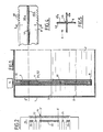
- the probe 4 comprises a support 8 fixed inside the thimble and a set of windings 10 having for axis the vertical axis of the support 8 and the thimble, these windings being constituted by the electric conductive wires 12 wound with substantially contiguous turns on the support 8.
- the ends of electrical conductors 12 are connected to the circuits of the level determination means 6.
- the windings 10 constitute a continuous primary winding 14 and a secondary winding 15 comprising successive windings in the vertical direction corresponding to the axis of the support and the thermowell.
- the turns of the secondary winding 15 are interposed and placed in a substantially contiguous manner, between the turns of the primary winding 14. Also shown in FIG. 2, the extreme positions 3 ′ and 3 ′ of the upper level 3 of the conductive medium 2, relative to the position of the windings 14 and 15, when these windings are in the measurement position in the thermowell 7 inside the 'envelope 1.
- the coils 14 and 15 which extend along the support 8 of the probe, over a substantially identical length, completely cover the measuring range 3' 3 ", in the vertical direction.
- the secondary winding 15 consists of five successive and separate windings21, 22, 23, 24 and 25.
- the windings 21 and 25 have the same number of turns and are placed entirely above the level 3 "in the case of the winding 21, and entirely below the level 3 ′ in the case of the winding 25.
- L winding 21 is thus always above the upper level of the conductive medium while winding 25 is always below this level and therefore entirely surrounded by conductive liquid metal.
- Windings 22 and 24 with a small number of turns are placed just above the level 3 "and just below the level 3 ', respectively.
- the central winding 23 has a length substantially equal to the vertical distance separating the levels 3 'and 3 "and is placed between these two levels.
- Fig. 3 all the electronic circuits constituting the supply means 17 of the primary winding 14 have been shown, the ends of the conductors 12 of which are connected to the output terminals 18 of the supply device 17 and, on the other hand ie means 19 for determining the level of the conducting medium in the casing 1 of the tank.
- the level determination means 19 comprises a set of input terminals 20 grouped in pairs, for the connection of the secondary windings 21, 22, 23, 24 and 25 of the probe, at the locations indicated in FIG. 3.
- the primary winding supply means 14 comprises an oscillator 26 providing a rectangular signal, a filter 27 and a power amplifier 28 making it possible to supply a current substantially regulated in frequency and in amplitude, to the primary of a transformer 29.
- the terminals output 18 of the supply means 17 to which the ends of the primary winding 14 are connected correspond to the terminals of the secondary of the transformer 29. A current substantially regulated in frequency and in amplitude is thus supplied to the primary winding 14 of the probe .
- the level 19 determination means comprises three sub-assemblies 19a, 19b and 19c.
- the sub-assembly 19a comprises five transformers 30 connected, on the primary side, via the input terminals 20, with the windings of the secondary winding 15, in the order indicated in FIG. 3.
- the transformers 30 are connected on the secondary side to five detection units 31 which thus receive a signal whose voltage is proportional to the voltage induced in the secondary winding, by the primary winding 14 supplied by the means 17.
- the sub assembly 19a comprising the detection modules 31 constitutes the detection stage of the level measurement means.
- the detection modules 31 provide analog signals representative of the amplitude and phase of the voltages induced in the windings of the secondary winding 15 of the probe.
- the analog signals corresponding to the extreme windings 21 and 25 and to the central winding 23 of the winding 15 are transmitted to the sub-assembly 19b of the processing and determination means 19 which constitutes the calculation stage of the level determination means 19.
- U25, U21 and U23 denote the respective electrical voltages of the analog signals corresponding to the secondary windings 25, 21 and 23;
- K denotes the ratio of the number of turns of the secondary windings 23 and 21 or 23 and 25, the windings 21 and 25 being identical.
- the computation stage 19b comprises an attenuator 32, summers 34 and 35, a signal comparator 36 and an analog multiplier 38.
- the attenuator 32 receiving an amplitude signal _ U23 at the input is designed to provide an output signal amplitude U23 / K. This signal at the output of the attenuator 32 is supplied in the form of a signal - negative to the summator 35.
- the analog signals corresponding respectively to the secondary windings 21 and 25, of respective amplitude U21 and U25 are sent to the summator 34, under form of a positive signal and a negative signal respectively.
- the voltage signal U21 is also sent in the form of a positive signal to the adder 35.
- the set of comparator 36 and analog multiplier 38 constitutes a divider receiving the analog signals of amplitude U21 -U25 coming from adder 34 and U21 -U23 / K coming from the summator 35.
- This amplitude signal ⁇ is representative of the level of the conductive medium in the envelope 1 of the reservoir.
- the voltages U21, U23 and U25 respectively are proportional to the voltages induced in the windings 21, 23 and 25, respectively, with the same proportionality factor resulting from the design of the transformers 30 and of the detection modules 31.
- the windings 21 and 25 being identical and the voltage U23 being divided by the number K corresponding to the ratio of the turns of the coils 21 and 23, the voltages combined to produce the signal a are all relative to the same number of turns.
- the voltage U21 corresponds to the voltage induced by the primary winding in a winding located in the air, above the level of the conductive medium
- the voltage U25 corresponds to the voltage induced by the primary winding in a secondary winding located entirely in the conducting medium while the voltage U23 / K corresponding to the voltage induced in a winding having the same number of turns as the windings U21 and U25 situated partly in the air and partly in the conducting medium.
- the ratio of the voltage differences corresponding to the amplitude of the signal therefore perfectly reflects the fraction of the winding 23 located in the conducting medium.
- the signal ⁇ will have the value zero when level 3 of the conductive medium is located in 3 'and the value one when this level 3 is located in 3 ".
- the signal obtained by making the ratio of signals detected under the same conditions with regard to the nature and the temperature of the medium of which the level is measured, independently of any prior calibration is practically insensitive to temperature variations of the conducting medium and independent of the nature of this conducting medium.
- the ratio a is obtained in the form of an analog signal, the amplitude of which directly translates the position of level 3 as a fraction of the measurement range corresponding to the vertical distance between the extreme levels 3 'and 3 ".
- This analog signal directly translating the position of level 3 is collected on output 39, to be displayed in a known manner, for example on an electronic voltmeter.
- the level measurement means 19 further comprises a discrimination stage 19c receiving the signals at the output of the detection modules 31 corresponding to the secondary windings 22 and 24 placed on either side of the central winding 23.
- a discrimination stage 19c receiving the signals at the output of the detection modules 31 corresponding to the secondary windings 22 and 24 placed on either side of the central winding 23.
- a particular embodiment of the support 8 of the windings can be seen, this support being constituted by a profile with a cruciform section visible in FIG. 5.
- a cruciform profile made of a material such as stainless steel can be obtained by welding two angles 45a and 45b along their edge 46.
- the support 8 thus' produced has notches 48 over its entire length useful to the inside which the conductors 12 are wound to form the successive turns of the primary and secondary windings, the turns of the secondary windings being interposed between the turns of the primary winding.
- the detection modules 31 receive the signal at the output of the oscillator 26 of the primary supply means 17. This signal perfectly translates the frequency and the amplitude of the excitation current of the primary winding. By varying this amplitude and this excitation frequency, it has been found that the level measurement is very insensitive to variations in amplitude and frequency of the excitation current. It is therefore possible to use an alternating current generator of excitation of a very simple design, its performances playing very little on the precision of the level measurement.
- the main advantages of the device according to the invention are the obtaining of very good measurement accuracy, without calibration prior to measurement, which allows the device to be used in environments with different resistivities without any intermediate operation, a small variation in the measured values, as a function of the temperature of the conducting medium, a small variation as a function of the frequency and the amplitude of the excitation current of the probe as well as satisfactory and reproducible performance despite a simple design of the device .
- the invention is not limited to the embodiment which has been described.
- a number of windings other than five can be used to constitute the secondary winding, this number of windings having to be at least equal to three in the simplest case where the secondary winding comprises a central winding. whose length is substantially equal to the vertical distance between the extreme levels to be measured and two identical extreme windings.
- the secondary winding comprises a central winding. whose length is substantially equal to the vertical distance between the extreme levels to be measured and two identical extreme windings.
- a stainless steel support in the form of a cruciform profile, it is possible to use a support constituted by an elongated cylinder made of magnetic material, which makes it possible to have higher level output signals.
- electrical conductors with insulator of the conventional type can be used to form the windings.
- refractory electrical conductors, with thermal insulation, such as conductors of the Pyrotenax type will be used.
- the level measurement device applies apart from measuring the level of liquid sodium in certain parts of a fast neutron nuclear reactor; it can be applied to the measurement of the level of metals li whatever, electrolytic solutions, grain powders or metallic pellets in tanks or in pipes forming part of various industrial installations.
Landscapes
- Physics & Mathematics (AREA)
- Engineering & Computer Science (AREA)
- Electromagnetism (AREA)
- Power Engineering (AREA)
- Thermal Sciences (AREA)
- Fluid Mechanics (AREA)
- General Physics & Mathematics (AREA)
- Measurement Of Levels Of Liquids Or Fluent Solid Materials (AREA)
Applications Claiming Priority (2)
| Application Number | Priority Date | Filing Date | Title |
|---|---|---|---|
| FR8506161 | 1985-04-23 | ||
| FR8506161A FR2580801B1 (fr) | 1985-04-23 | 1985-04-23 | Dispositif de mesure de niveau d'un milieu conducteur electrique contenu dans une enveloppe et ses applications |
Publications (2)
| Publication Number | Publication Date |
|---|---|
| EP0200619A1 true EP0200619A1 (de) | 1986-11-05 |
| EP0200619B1 EP0200619B1 (de) | 1989-04-19 |
Family
ID=9318572
Family Applications (1)
| Application Number | Title | Priority Date | Filing Date |
|---|---|---|---|
| EP19860400771 Expired EP0200619B1 (de) | 1985-04-23 | 1986-04-10 | Einrichtung zum Messen des Niveaus von in einem Behälter enthaltenem elektrisch leitendem Material und ihre Anwendungen |
Country Status (3)
| Country | Link |
|---|---|
| EP (1) | EP0200619B1 (de) |
| DE (1) | DE3662948D1 (de) |
| FR (1) | FR2580801B1 (de) |
Cited By (1)
| Publication number | Priority date | Publication date | Assignee | Title |
|---|---|---|---|---|
| FR2736433A1 (fr) * | 1995-07-04 | 1997-01-10 | Carbonnel Henri | Perfectionnement aux dispositifs de mesure du niveau des metaux liquides en fonderie |
Families Citing this family (1)
| Publication number | Priority date | Publication date | Assignee | Title |
|---|---|---|---|---|
| US5680055A (en) * | 1995-07-19 | 1997-10-21 | Marquette University | Method and apparatus to sense changes in the state of a resin bed |
Citations (6)
| Publication number | Priority date | Publication date | Assignee | Title |
|---|---|---|---|---|
| FR2169711A1 (de) * | 1971-12-24 | 1973-09-14 | Commissariat Energie Atomique | |
| FR2242669A1 (de) * | 1973-08-30 | 1975-03-28 | Mine Safety Appliances Co | |
| US4152937A (en) * | 1976-02-10 | 1979-05-08 | Westinghouse Electric Corp. | Liquid level sensor |
| US4170754A (en) * | 1975-10-16 | 1979-10-09 | Westinghouse Electric Corp. | Phase encoded digital position probe assembly |
| EP0019816A1 (de) * | 1979-05-31 | 1980-12-10 | INTERATOM Internationale Atomreaktorbau GmbH | Flexibler, kontinuierlicher Füllstandsmesser für elektrisch leitende Flüssigkeiten |
| EP0087382A1 (de) * | 1982-02-23 | 1983-08-31 | Stopinc Aktiengesellschaft | Verfahren zum Messen des Füllstandes von flüssigen Metallen in Stranggiesskokillen |
-
1985
- 1985-04-23 FR FR8506161A patent/FR2580801B1/fr not_active Expired
-
1986
- 1986-04-10 EP EP19860400771 patent/EP0200619B1/de not_active Expired
- 1986-04-10 DE DE8686400771T patent/DE3662948D1/de not_active Expired
Patent Citations (6)
| Publication number | Priority date | Publication date | Assignee | Title |
|---|---|---|---|---|
| FR2169711A1 (de) * | 1971-12-24 | 1973-09-14 | Commissariat Energie Atomique | |
| FR2242669A1 (de) * | 1973-08-30 | 1975-03-28 | Mine Safety Appliances Co | |
| US4170754A (en) * | 1975-10-16 | 1979-10-09 | Westinghouse Electric Corp. | Phase encoded digital position probe assembly |
| US4152937A (en) * | 1976-02-10 | 1979-05-08 | Westinghouse Electric Corp. | Liquid level sensor |
| EP0019816A1 (de) * | 1979-05-31 | 1980-12-10 | INTERATOM Internationale Atomreaktorbau GmbH | Flexibler, kontinuierlicher Füllstandsmesser für elektrisch leitende Flüssigkeiten |
| EP0087382A1 (de) * | 1982-02-23 | 1983-08-31 | Stopinc Aktiengesellschaft | Verfahren zum Messen des Füllstandes von flüssigen Metallen in Stranggiesskokillen |
Cited By (1)
| Publication number | Priority date | Publication date | Assignee | Title |
|---|---|---|---|---|
| FR2736433A1 (fr) * | 1995-07-04 | 1997-01-10 | Carbonnel Henri | Perfectionnement aux dispositifs de mesure du niveau des metaux liquides en fonderie |
Also Published As
| Publication number | Publication date |
|---|---|
| DE3662948D1 (en) | 1989-05-24 |
| EP0200619B1 (de) | 1989-04-19 |
| FR2580801A1 (fr) | 1986-10-24 |
| FR2580801B1 (fr) | 1987-07-10 |
Similar Documents
| Publication | Publication Date | Title |
|---|---|---|
| Gardner et al. | Calibration and comparison of the LDGO nephelometer and the OSU transmissometer on the Nova Scotian Rise | |
| US5854557A (en) | Corrosion measurement system | |
| US4188826A (en) | Device for measuring the liquid level of an electrically conductive liquid | |
| FR2488406A1 (fr) | Procede et instrument de mesure de corrosion a compensation de temperature secondaire | |
| FR2663115A1 (fr) | Procede et dispositif de controle de l'epaisseur et de la cohesion de l'interface d'un tube duplex. | |
| EP0657734A1 (de) | Mikroeinrichtung zur Messung der elektromagnetischen charakteristiken eines Mediums, sowie Anwendung dieser Mikroeinrichtung | |
| EP0583993A1 (de) | Mess-/Anordnung und -verfahren ab Grundniveau für Hochspannungsluftleitungen | |
| US5144247A (en) | Method and apparatus for reducing IR error in cathodic protection measurements | |
| JPS6014127A (ja) | 液体レベル遠隔測定用の装置 | |
| FR2571845A1 (fr) | Systeme de mesure de distance inductif sans contact, notamment pour la detection du niveau d'un bain de metal liquide | |
| US5583426A (en) | Method and apparatus for determining corrosivity of fluids on metallic materials | |
| EP3067704B1 (de) | Vorrichtung zum messen eines elektrischen felds in einem leitenden medium, und kalibrierverfahren dieser vorrichtung | |
| EP0200619B1 (de) | Einrichtung zum Messen des Niveaus von in einem Behälter enthaltenem elektrisch leitendem Material und ihre Anwendungen | |
| EP0013224B1 (de) | Verfahren und Gerät zur Messung des spezifischen Bohrlochflüssigkeitswiderstandes | |
| US4319484A (en) | Linear response capacitance wave height measuring system | |
| FR2493530A1 (fr) | Detecteur de neutrons auto-alimente et procede de mesure correspondant | |
| CA1118495A (en) | Sea water conductivity cell | |
| EP0557225B1 (de) | Kompensationsgerät für die kalte Verbindung eines Thermoelements | |
| CH574105A5 (en) | Measurement of density and water content esp. for snow - by measuring permittivity using two different frequencies | |
| FR2701566A1 (fr) | Procédé de mesure d'au moins une caractéristique d'une solution liquide et moyens pour la mise en Óoeuvre de la dite solution. | |
| EP0492394B1 (de) | Gerät zur zerstörungsfreien Untersuchung mit Wirbelströmen mit Umschaltung zur Flussaddition-Flusssubtraktion | |
| EP0186584B1 (de) | Vorrichtung zur Nachweisung eines eingeschlossenen elektrisch leitenden Materials und Verwendungen dieser Vorrichtung | |
| US3728622A (en) | Method of and apparatus for measuring in situ the formation factor | |
| FR2693797A1 (fr) | Système de contrôle de canalisations, notamment de canalisations en acier nu ou enrobé. | |
| EP0128824A1 (de) | Verfahren und Vorrichtung zur Stellungsüberwachung eines im Innern eines dickwandigen Gehäuses angeordneten Schiebers |
Legal Events
| Date | Code | Title | Description |
|---|---|---|---|
| PUAI | Public reference made under article 153(3) epc to a published international application that has entered the european phase |
Free format text: ORIGINAL CODE: 0009012 |
|
| 17P | Request for examination filed |
Effective date: 19861010 |
|
| AK | Designated contracting states |
Kind code of ref document: A1 Designated state(s): BE DE GB IT NL |
|
| PUAB | Information related to the publication of an a document modified or deleted |
Free format text: ORIGINAL CODE: 0009199EPPU |
|
| PUAF | Information related to the publication of a search report (a3 document) modified or deleted |
Free format text: ORIGINAL CODE: 0009199SEPU |
|
| R17D | Deferred search report published (corrected) |
Effective date: 19861210 |
|
| RA1 | Application published (corrected) |
Date of ref document: 19861210 Kind code of ref document: A1 |
|
| 17Q | First examination report despatched |
Effective date: 19880325 |
|
| GRAA | (expected) grant |
Free format text: ORIGINAL CODE: 0009210 |
|
| AK | Designated contracting states |
Kind code of ref document: B1 Designated state(s): BE DE GB IT NL |
|
| ITF | It: translation for a ep patent filed | ||
| GBT | Gb: translation of ep patent filed (gb section 77(6)(a)/1977) | ||
| REF | Corresponds to: |
Ref document number: 3662948 Country of ref document: DE Date of ref document: 19890524 |
|
| PLBE | No opposition filed within time limit |
Free format text: ORIGINAL CODE: 0009261 |
|
| STAA | Information on the status of an ep patent application or granted ep patent |
Free format text: STATUS: NO OPPOSITION FILED WITHIN TIME LIMIT |
|
| 26N | No opposition filed | ||
| ITPR | It: changes in ownership of a european patent |
Owner name: FUSIONI;FRAMATOME |
|
| PGFP | Annual fee paid to national office [announced via postgrant information from national office to epo] |
Ref country code: BE Payment date: 19910424 Year of fee payment: 6 |
|
| PGFP | Annual fee paid to national office [announced via postgrant information from national office to epo] |
Ref country code: NL Payment date: 19910430 Year of fee payment: 6 |
|
| NLS | Nl: assignments of ep-patents |
Owner name: FRAMATOME TE COURBEVOIE, FRANKRIJK. |
|
| REG | Reference to a national code |
Ref country code: GB Ref legal event code: 732 |
|
| PG25 | Lapsed in a contracting state [announced via postgrant information from national office to epo] |
Ref country code: BE Effective date: 19920430 |
|
| BERE | Be: lapsed |
Owner name: FRAMATOME Effective date: 19920430 |
|
| PG25 | Lapsed in a contracting state [announced via postgrant information from national office to epo] |
Ref country code: NL Effective date: 19921101 |
|
| NLV4 | Nl: lapsed or anulled due to non-payment of the annual fee | ||
| ITTA | It: last paid annual fee | ||
| PGFP | Annual fee paid to national office [announced via postgrant information from national office to epo] |
Ref country code: DE Payment date: 19940318 Year of fee payment: 9 |
|
| PG25 | Lapsed in a contracting state [announced via postgrant information from national office to epo] |
Ref country code: DE Effective date: 19960103 |
|
| PGFP | Annual fee paid to national office [announced via postgrant information from national office to epo] |
Ref country code: GB Payment date: 19970326 Year of fee payment: 12 |
|
| PG25 | Lapsed in a contracting state [announced via postgrant information from national office to epo] |
Ref country code: GB Free format text: LAPSE BECAUSE OF NON-PAYMENT OF DUE FEES Effective date: 19980410 |
|
| GBPC | Gb: european patent ceased through non-payment of renewal fee |
Effective date: 19980410 |
|
| PG25 | Lapsed in a contracting state [announced via postgrant information from national office to epo] |
Ref country code: IT Free format text: LAPSE BECAUSE OF NON-PAYMENT OF DUE FEES;WARNING: LAPSES OF ITALIAN PATENTS WITH EFFECTIVE DATE BEFORE 2007 MAY HAVE OCCURRED AT ANY TIME BEFORE 2007. THE CORRECT EFFECTIVE DATE MAY BE DIFFERENT FROM THE ONE RECORDED. Effective date: 20050410 |