EP0200623B1 - Radiologische Vorrichtung - Google Patents
Radiologische Vorrichtung Download PDFInfo
- Publication number
- EP0200623B1 EP0200623B1 EP86400809A EP86400809A EP0200623B1 EP 0200623 B1 EP0200623 B1 EP 0200623B1 EP 86400809 A EP86400809 A EP 86400809A EP 86400809 A EP86400809 A EP 86400809A EP 0200623 B1 EP0200623 B1 EP 0200623B1
- Authority
- EP
- European Patent Office
- Prior art keywords
- image
- plate
- installation
- optical transmission
- radiological
- Prior art date
- Legal status (The legal status is an assumption and is not a legal conclusion. Google has not performed a legal analysis and makes no representation as to the accuracy of the status listed.)
- Expired
Links
Images

Classifications
-
- G—PHYSICS
- G03—PHOTOGRAPHY; CINEMATOGRAPHY; ANALOGOUS TECHNIQUES USING WAVES OTHER THAN OPTICAL WAVES; ELECTROGRAPHY; HOLOGRAPHY
- G03B—APPARATUS OR ARRANGEMENTS FOR TAKING PHOTOGRAPHS OR FOR PROJECTING OR VIEWING THEM; APPARATUS OR ARRANGEMENTS EMPLOYING ANALOGOUS TECHNIQUES USING WAVES OTHER THAN OPTICAL WAVES; ACCESSORIES THEREFOR
- G03B7/00—Control of exposure by setting shutters, diaphragms or filters, separately or conjointly
- G03B7/28—Circuitry to measure or to take account of the object contrast
-
- G—PHYSICS
- G03—PHOTOGRAPHY; CINEMATOGRAPHY; ANALOGOUS TECHNIQUES USING WAVES OTHER THAN OPTICAL WAVES; ELECTROGRAPHY; HOLOGRAPHY
- G03B—APPARATUS OR ARRANGEMENTS FOR TAKING PHOTOGRAPHS OR FOR PROJECTING OR VIEWING THEM; APPARATUS OR ARRANGEMENTS EMPLOYING ANALOGOUS TECHNIQUES USING WAVES OTHER THAN OPTICAL WAVES; ACCESSORIES THEREFOR
- G03B42/00—Obtaining records using waves other than optical waves; Visualisation of such records by using optical means
- G03B42/02—Obtaining records using waves other than optical waves; Visualisation of such records by using optical means using X-rays
-
- H—ELECTRICITY
- H04—ELECTRIC COMMUNICATION TECHNIQUE
- H04N—PICTORIAL COMMUNICATION, e.g. TELEVISION
- H04N23/00—Cameras or camera modules comprising electronic image sensors; Control thereof
- H04N23/30—Cameras or camera modules comprising electronic image sensors; Control thereof for generating image signals from X-rays
-
- H—ELECTRICITY
- H04—ELECTRIC COMMUNICATION TECHNIQUE
- H04N—PICTORIAL COMMUNICATION, e.g. TELEVISION
- H04N23/00—Cameras or camera modules comprising electronic image sensors; Control thereof
- H04N23/70—Circuitry for compensating brightness variation in the scene
- H04N23/75—Circuitry for compensating brightness variation in the scene by influencing optical camera components
-
- H—ELECTRICITY
- H05—ELECTRIC TECHNIQUES NOT OTHERWISE PROVIDED FOR
- H05G—X-RAY TECHNIQUE
- H05G1/00—X-ray apparatus involving X-ray tubes; Circuits therefor
- H05G1/08—Electrical details
- H05G1/64—Circuit arrangements for X-ray apparatus incorporating image intensifiers
Definitions
- the invention relates to a radiology installation provided with means for compressing the dynamics of the radiological image with a view to better exploitation of the inherent dynamics of the image acquisition means, such as in particular a television camera.
- the invention proposes in particular to transpose this concept, with means of a different nature, in a radiology installation comprising optical transmission means between an output screen of a receiver of the radiological image (for example a luminance amplifier ) and means for acquiring the image (for example a television camera).
- the basic idea of the invention therefore consists in carrying out the dynamic compensation processing in the optical path of the image (by generating a kind of fuzzy mask there), upstream of the acquisition means whose own dynamic would be too limited for precise acquisition of low contrasts.
- the invention therefore essentially relates to a radiology installation of the type comprising optical transmission means between an output screen of a receiver of the radiological image and a two-dimensional image sensor, such as a camera. television, said optical transmission means comprising a system of lenses or objectives for capturing the visible image delivered by said output screen and reforming it on said two-dimensional sensor, characterized in that it comprises an optical attenuator with transmission adjustable in at least a certain number of zones, interposed in said optical transmission means and placed at least in the vicinity of a focal plane of said system of lenses or objectives where a real image of said visible image is reformed and in that it further comprises means for adjusting the transmission of each aforementioned zone as a function of the quantity of light received by it.
- the optical attenuator can come in very different forms.
- These components require significant light energy to be "impressed” correctly, so we must provide in this case means to temporarily increase the brightness of the transmitted image.
- the great "optical inertia" of such a component becomes an advantage in since, for example, there is then sufficient time to observe the development of a contrast product, without the attenuation characteristics of the blade, defined by the pre-lumination thereof, being have time to change significantly.
- each cell is controlled by independent means, in particular photosensitive sensors (photodiodes) arranged in a similar flat mosaic and placed at least in the vicinity of an auxiliary plane where a real image of said visible image is reformed.
- photosensitive sensors photodiodes
- An advantage of this system lies in the fact that one can memorize the values delivered by the photosensitive sensors for a given image forming a mask and "freeze" the attenuation configuration of the mosaic of attenuating cells for all a series of images taken. later. The resolution of the mask (dimensions of the attenuating cells) can be compared to that of the image.
- each attenuating cell can also be much coarser, each attenuating cell being associated with a more or less important area of the image.
- the offset of the mosaic of attenuating cells of the focal plane will in particular attenuate the defects resulting from the poor resolution of the mask.
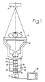
- FIG. 1 represents a radiology installation which conventionally comprises an X-ray tube 11, a receiver, constituted here by a luminance amplifier 12, a television camera 13 and means for optical transmission 14 inserted between an output screen 14a of the amplifier 12 and the camera 13.
- the body 15 to be represented is placed on a table 17 between the generator tube 11 and the luminance amplifier which gives a visible image taken up by the optical transmission system then by the television camera 13.
- the video signal delivered by the latter is transmitted to a television receiver 18.
- the optical transmission means 14 comprise two lenses or objectives 20, 21 having an optical axis common 22.
- the lens or objective 20 is arranged so that its focal plane is coincident with the plane of the screen 14a, to give an image "at infinity" which is taken up by the lens the or objective 21 which transforms a real image into a plane 25.
- the objective 26 of the camera takes this real image and reforms it on the target of the analyzer tube of the television camera 13.
- the arrangement of the optical transmission means described above is specific to the invention since it defines a plane 25 in which is placed an optical attenuator 28 with locally adjustable transmission. The latter is therefore inserted in said optical transmission means 14 and more particularly placed in the focal plane 25 where there is reformed a real image of the radiological image taken from the output screen 14a.
- the attenuator 28 can be slightly offset from said focal plane and its position along the axis 22 can also be adjustable.
- the attenuator consists of a photochromic glass slide.
- the local attenuation control of this attenuator is therefore optical and operated by the image itself since the attenuation at each point of the photochromic plate increases with the amount of light received at this point.
- the low sensitivity and "inertia" of currently known photochromic lenses require a prelumination device to "impress" the attenuator, prior to a period of use.
- the camera's analyzer tube can be protected by a mechanical or electro-optical shutter or else by cutting its own beam. The entire series of images following the pre-illumination therefore benefits from the same compensation given the relatively long equilibrium return time of such a material.
- FIG. 2 in which the similar structural elements bear the same numerical references, illustrates an installation of the same type in which the attenuator 28a is always of the type with direct optical control by the image itself, but essentially consisting of the 'association of a variable attenuation blade, for example liquid crystal, and a transparent blade of a photoconductive material.
- a variable attenuation blade for example liquid crystal
- a transparent blade of a photoconductive material Such systems have for example been described in an article in the journal "OPTICAL ENGINEERING" volume 17 W4 of JULY 1978.
- the arrangement may be in accordance with the diagram of FIG. 3, comprising a blade 35 of material endowed with electro-optical properties (for example in the form of liquid crystal of formula Bi, 2 , Si0 2o ) to which is attached a photoconductive strip 36.
- FIG. 4 illustrates another type of attenuator in a similar installation.
- the attenuator 28b consists of a mosaic of attenuating cells 45 with liquid crystals (FIG. 5) which are controlled individually by electrical control means comprising as input sensors photosensitive components 46, for example photodiodes, arranged in a mosaic similar to the mosaic of attenuating cells, placed in an auxiliary plane 47 where a real image of the image delivered by the output screen 14a of the luminance amplifier 12 is reformed, or else at neighborhood of this plane.
- photosensitive components 46 for example photodiodes
- the optical transmission means 14 comprise a semi-transparent mirror 48 oriented at 45 ° relative to the axis 22 and arranged in the “infinite” portion of the optical path, as well as a lens or objective 49 arranged to receive the light reflected by this mirror and to reform a real image in the auxiliary plane 47.
- the transmission coefficients of the cells 45 depend on the control voltages applied to them.
- the definition of the mask defined by the mosaic can be relatively coarse if it is shifted slightly from the focal plane 25.
- the electrical control means 50 between the photodiodes 46 and the attenuating cells 45 advantageously include a memory capable of storing the set of information representative of the signals delivered by the photodiodes 46, in order to "freeze" the configuration of a reference image forming a mask during a whole sequence of observations.
- the system of Figures 4 and 5 can be modified. We can indeed remove the mosaic of photodiodes 46 (as well as the mirror 48 and the lens 49) and in this case, a reference image can be taken at the start of the examination by the camera 13 itself if all the cells attenuators have been previously piloted to momentarily present the same attenuation. This reference image is then analyzed by zones corresponding to the definition of the mask defined by the mosaic and the corresponding control values stored in the memory of the electrical control means 50.
Landscapes
- Physics & Mathematics (AREA)
- General Physics & Mathematics (AREA)
- Engineering & Computer Science (AREA)
- Multimedia (AREA)
- Signal Processing (AREA)
- Transforming Light Signals Into Electric Signals (AREA)
Claims (10)
Applications Claiming Priority (2)
| Application Number | Priority Date | Filing Date | Title |
|---|---|---|---|
| FR8506008 | 1985-04-19 | ||
| FR8506008A FR2580827B1 (fr) | 1985-04-19 | 1985-04-19 | Installation de radiologie |
Publications (2)
| Publication Number | Publication Date |
|---|---|
| EP0200623A1 EP0200623A1 (de) | 1986-11-05 |
| EP0200623B1 true EP0200623B1 (de) | 1988-11-23 |
Family
ID=9318460
Family Applications (1)
| Application Number | Title | Priority Date | Filing Date |
|---|---|---|---|
| EP86400809A Expired EP0200623B1 (de) | 1985-04-19 | 1986-04-15 | Radiologische Vorrichtung |
Country Status (4)
| Country | Link |
|---|---|
| US (1) | US4749257A (de) |
| EP (1) | EP0200623B1 (de) |
| DE (1) | DE3661299D1 (de) |
| FR (1) | FR2580827B1 (de) |
Families Citing this family (20)
| Publication number | Priority date | Publication date | Assignee | Title |
|---|---|---|---|---|
| FR2610735A1 (fr) * | 1987-02-06 | 1988-08-12 | Thomson Csf | Compensateur de dynamique optique autoadaptatif et son utilisation dans une chaine optique d'imagerie radiologique |
| DE8807444U1 (de) * | 1987-10-06 | 1989-02-02 | Siemens AG, 1000 Berlin und 8000 München | Röntgendiagnostikvorrichtung mit einer Bildverstärker-Fernsehkette |
| DE8714009U1 (de) * | 1987-10-19 | 1989-02-16 | Siemens AG, 1000 Berlin und 8000 München | Röntgendiagnostikvorrichtung |
| US4918534A (en) * | 1988-04-22 | 1990-04-17 | The University Of Chicago | Optical image processing method and system to perform unsharp masking on images detected by an I.I./TV system |
| USH737H (en) | 1988-08-18 | 1990-02-06 | The United States Of America As Represented By The United States Department Of Energy | Light intensity compressor |
| DE58905397D1 (de) * | 1989-05-10 | 1993-09-30 | Siemens Ag | Röntgendiagnostikeinrichtung. |
| JP2548018Y2 (ja) * | 1990-01-24 | 1997-09-17 | 興和 株式会社 | X線撮像装置 |
| DE4005111A1 (de) * | 1990-02-17 | 1991-08-22 | Philips Patentverwaltung | Roentgendiagnostikgeraet mit mitteln zur vergroesserten visuellen darstellung eines waehlbaren ausschnitts des gesamt-bildbereichs |
| JP3188491B2 (ja) * | 1990-10-24 | 2001-07-16 | コーニンクレッカ フィリップス エレクトロニクス エヌ ヴィ | X線記録のダイナミック圧縮方法及びその装置 |
| US5319733A (en) * | 1992-01-02 | 1994-06-07 | Adc Telecommunications, Inc. | Variable fiber optical attenuator |
| EP0694173A1 (de) * | 1992-01-02 | 1996-01-31 | Adc Telecommunications, Inc. | Überlappendes geschweistes dämpfungsglied |
| DE69327809T2 (de) | 1992-11-27 | 2000-10-12 | Voxel, Laguna Hills | Verfahren und vorrichtung zur herstellung von hologrammen |
| US5903247A (en) * | 1996-07-19 | 1999-05-11 | The Regents Of The University Of California | Servo controlled liquid crystal windows |
| US6507638B2 (en) * | 2001-05-30 | 2003-01-14 | Ge Medical Systems Global Technology Company Llc | X-ray imaging optical camera apparatus and method of use |
| US7034492B2 (en) * | 2003-10-28 | 2006-04-25 | Ge Medical Systems Global Technology Company, Llc | Methods and systems for reducing unintentional collisions |
| US20080212180A1 (en) * | 2007-03-02 | 2008-09-04 | Jingyun Zhang | Polarization independent raman imaging with liquid crystal tunable filter |
| US8289513B2 (en) * | 2009-05-01 | 2012-10-16 | Chemimage Corporation | System and method for component discrimination enhancement based on multispectral addition imaging |
| US8988680B2 (en) | 2010-04-30 | 2015-03-24 | Chemimage Technologies Llc | Dual polarization with liquid crystal tunable filters |
| US9052290B2 (en) | 2012-10-15 | 2015-06-09 | Chemimage Corporation | SWIR targeted agile raman system for detection of unknown materials using dual polarization |
| US9157800B2 (en) | 2013-01-15 | 2015-10-13 | Chemimage Technologies Llc | System and method for assessing analytes using conformal filters and dual polarization |
Family Cites Families (14)
| Publication number | Priority date | Publication date | Assignee | Title |
|---|---|---|---|---|
| US3476029A (en) * | 1967-08-16 | 1969-11-04 | Graflex Inc | Electrochromic shutter system |
| US3622786A (en) * | 1969-11-19 | 1971-11-23 | Gen Electric | X-ray image converter using a high performance folded objective lens |
| AT310831B (de) * | 1971-04-29 | 1973-10-25 | Eumig | Sucher |
| US4025191A (en) * | 1975-03-12 | 1977-05-24 | Corning Glass Works | Photographic contrast enhancement system using photochromic glass |
| NL7600142A (nl) * | 1976-01-08 | 1977-07-12 | Philips Nv | Werkwijze en inrichting voor het afregelen van een beeldversterkerketen. |
| US4063092A (en) * | 1976-04-09 | 1977-12-13 | The United States Of America As Represented By The Administrator Of The National Aeronautics And Space Administration | Selective image area control of x-ray film exposure density |
| DE2651307C2 (de) * | 1976-11-10 | 1983-02-17 | Siemens AG, 1000 Berlin und 8000 München | Röntgendiagnostikeinrichtung mit einem elektronischen Übertragungskanal für das Röntgenbild |
| NL8200852A (nl) * | 1982-03-03 | 1983-10-03 | Philips Nv | Roentgenonderzoekinrichting. |
| JPS58209273A (ja) * | 1982-05-31 | 1983-12-06 | Eiichi Takenaka | X線テレビジヨン撮像装置 |
| DE3225061A1 (de) * | 1982-07-05 | 1984-01-05 | Siemens AG, 1000 Berlin und 8000 München | Roentgendiagnostikeinrichtung |
| JPS59118135A (ja) * | 1982-12-27 | 1984-07-07 | 株式会社東芝 | X線診断装置 |
| JPS59180452A (ja) * | 1983-03-31 | 1984-10-13 | Toshiba Corp | パルスx線診断装置 |
| DE3319309A1 (de) * | 1983-05-27 | 1984-11-29 | Siemens AG, 1000 Berlin und 8000 München | Roentgendiagnostikeinrichtung mit einem flachbildverstaerker |
| US4497062A (en) * | 1983-06-06 | 1985-01-29 | Wisconsin Alumni Research Foundation | Digitally controlled X-ray beam attenuation method and apparatus |
-
1985
- 1985-04-19 FR FR8506008A patent/FR2580827B1/fr not_active Expired
-
1986
- 1986-04-15 DE DE8686400809T patent/DE3661299D1/de not_active Expired
- 1986-04-15 EP EP86400809A patent/EP0200623B1/de not_active Expired
- 1986-04-16 US US06/852,705 patent/US4749257A/en not_active Expired - Lifetime
Also Published As
| Publication number | Publication date |
|---|---|
| FR2580827B1 (fr) | 1987-05-22 |
| EP0200623A1 (de) | 1986-11-05 |
| US4749257A (en) | 1988-06-07 |
| FR2580827A1 (fr) | 1986-10-24 |
| DE3661299D1 (en) | 1988-12-29 |
Similar Documents
| Publication | Publication Date | Title |
|---|---|---|
| EP0200623B1 (de) | Radiologische Vorrichtung | |
| EP0256051B1 (de) | Bildverarbeitungsvorrichtung zur kontrolle der transferfunktion eines optischen systems | |
| EP1071974B1 (de) | Mikroskop für die erzeugung einer dreidimensionalen darstellung von einem objekt und bilder, die mittels dieses mikroskops erzeugt sind | |
| US4594507A (en) | Thermal imager | |
| CA1264580A (en) | Optical image processor | |
| EP0394137B1 (de) | Gerät für Holographie mit inkohärentem Licht | |
| EP2929310A1 (de) | Vorrichtung zum messen und regeln der wellenfront eines kohärenten lichtstrahls | |
| US6052432A (en) | Method of generating multiple x-ray images of an object from a single x-ray exposure | |
| EP0286529B1 (de) | Anordnung zur Bestimmung des Kontrastes eines Aufzeichnungsschirmes als Funktion der Beobachtungsrichtung | |
| Hofmann et al. | High-angular-resolution NIR astronomy with large arrays (SHARP I and SHARP II) | |
| EP0376837B1 (de) | Verfahren und Vorrichtung für Holographie mit inkohärentem Licht | |
| FR2612647A1 (fr) | Dispositif de modulation pour un dispositif detecteur de rayonnement captant un champ d'image | |
| CA3119232C (fr) | Appareil et procede pour observer une scene comportant une cible | |
| EP2176633A2 (de) | Verfahren zur schätzung mindestens einer deformation der wellenfront eines optischen systems oder eines durch das optische system beobachteten objekts und diesbezügliche einrichtung | |
| RU2812809C1 (ru) | Лазерный голографический локатор | |
| CA1263761A (fr) | Dispositif de traitement d'image pour le controle de la fonction de transfert d'un systeme optique | |
| FR2582502A1 (fr) | Installation de radiologie a compensateur global place dans un trajet optique de l'image | |
| FR2787566A1 (fr) | Procede et systeme d'aide a la visee pour arme legere | |
| Dumont et al. | The phototitus optical converter | |
| Xie et al. | Optical sparse aperture imaging with faint objects using improved spatial modulation diversity | |
| EP0751400B1 (de) | Verfahren und Vorrichtung für die optische Behandlung von zweidimensionalen Bildern, um das Geschwindigkeitsfeld zu gewinnen | |
| EP0593327A1 (de) | Infrarotkamera mit Schutz vor parasitären Intensitätsmodulationen des detektierten Lichtstroms | |
| FR2673794A1 (fr) | Dispositif de correction de defauts pour systemes d'imagerie. | |
| FR2593295A1 (fr) | Controleur electronique matriciel des parametres d'exposition pour appareil de prise de vues | |
| Clary et al. | Hydrogen-alpha auroral activity on Jupiter |
Legal Events
| Date | Code | Title | Description |
|---|---|---|---|
| PUAI | Public reference made under article 153(3) epc to a published international application that has entered the european phase |
Free format text: ORIGINAL CODE: 0009012 |
|
| AK | Designated contracting states |
Kind code of ref document: A1 Designated state(s): DE IT NL |
|
| PUAB | Information related to the publication of an a document modified or deleted |
Free format text: ORIGINAL CODE: 0009199EPPU |
|
| PUAF | Information related to the publication of a search report (a3 document) modified or deleted |
Free format text: ORIGINAL CODE: 0009199SEPU |
|
| R17D | Deferred search report published (corrected) |
Effective date: 19861210 |
|
| RA1 | Application published (corrected) |
Date of ref document: 19861210 Kind code of ref document: A1 |
|
| 17P | Request for examination filed |
Effective date: 19870318 |
|
| 17Q | First examination report despatched |
Effective date: 19880504 |
|
| GRAA | (expected) grant |
Free format text: ORIGINAL CODE: 0009210 |
|
| AK | Designated contracting states |
Kind code of ref document: B1 Designated state(s): DE IT NL |
|
| PG25 | Lapsed in a contracting state [announced via postgrant information from national office to epo] |
Ref country code: IT Free format text: LAPSE BECAUSE OF FAILURE TO SUBMIT A TRANSLATION OF THE DESCRIPTION OR TO PAY THE FEE WITHIN THE PRE;WARNING: LAPSES OF ITALIAN PATENTS WITH EFFECTIVE DATE BEFORE 2007 MAY HAVE OCCURRED AT ANY TIME BEFORE 2007. THE CORRECT EFFECTIVE DATE MAY BE DIFFERENT FROM THE ONE RECORDED.SCRIBED TIME-LIMIT Effective date: 19881123 |
|
| REF | Corresponds to: |
Ref document number: 3661299 Country of ref document: DE Date of ref document: 19881229 |
|
| PLBE | No opposition filed within time limit |
Free format text: ORIGINAL CODE: 0009261 |
|
| STAA | Information on the status of an ep patent application or granted ep patent |
Free format text: STATUS: NO OPPOSITION FILED WITHIN TIME LIMIT |
|
| 26N | No opposition filed | ||
| PGFP | Annual fee paid to national office [announced via postgrant information from national office to epo] |
Ref country code: DE Payment date: 19920326 Year of fee payment: 7 |
|
| PGFP | Annual fee paid to national office [announced via postgrant information from national office to epo] |
Ref country code: NL Payment date: 19930430 Year of fee payment: 8 |
|
| PG25 | Lapsed in a contracting state [announced via postgrant information from national office to epo] |
Ref country code: DE Effective date: 19940101 |
|
| PG25 | Lapsed in a contracting state [announced via postgrant information from national office to epo] |
Ref country code: NL Effective date: 19941101 |
|
| NLV4 | Nl: lapsed or anulled due to non-payment of the annual fee |