EP0200632A1 - Hydraulisches Bremssystem für Schienenfahrzeuge - Google Patents
Hydraulisches Bremssystem für Schienenfahrzeuge Download PDFInfo
- Publication number
- EP0200632A1 EP0200632A1 EP86400854A EP86400854A EP0200632A1 EP 0200632 A1 EP0200632 A1 EP 0200632A1 EP 86400854 A EP86400854 A EP 86400854A EP 86400854 A EP86400854 A EP 86400854A EP 0200632 A1 EP0200632 A1 EP 0200632A1
- Authority
- EP
- European Patent Office
- Prior art keywords
- pressure
- accumulator
- hydraulic
- actuator
- hydraulic fluid
- Prior art date
- Legal status (The legal status is an assumption and is not a legal conclusion. Google has not performed a legal analysis and makes no representation as to the accuracy of the status listed.)
- Granted
Links
- 239000012530 fluid Substances 0.000 claims abstract description 24
- 230000002457 bidirectional effect Effects 0.000 claims description 4
- 230000001105 regulatory effect Effects 0.000 claims description 4
- 230000001276 controlling effect Effects 0.000 claims description 2
- 238000007599 discharging Methods 0.000 claims 1
- 230000009471 action Effects 0.000 description 2
- 238000010586 diagram Methods 0.000 description 1
- 230000000694 effects Effects 0.000 description 1
- 238000012423 maintenance Methods 0.000 description 1
- 238000005259 measurement Methods 0.000 description 1
- 238000000034 method Methods 0.000 description 1
- 230000010355 oscillation Effects 0.000 description 1
- 230000008569 process Effects 0.000 description 1
- 230000008439 repair process Effects 0.000 description 1
- 230000032258 transport Effects 0.000 description 1
Images
Classifications
-
- B—PERFORMING OPERATIONS; TRANSPORTING
- B60—VEHICLES IN GENERAL
- B60T—VEHICLE BRAKE CONTROL SYSTEMS OR PARTS THEREOF; BRAKE CONTROL SYSTEMS OR PARTS THEREOF, IN GENERAL; ARRANGEMENT OF BRAKING ELEMENTS ON VEHICLES IN GENERAL; PORTABLE DEVICES FOR PREVENTING UNWANTED MOVEMENT OF VEHICLES; VEHICLE MODIFICATIONS TO FACILITATE COOLING OF BRAKES
- B60T8/00—Arrangements for adjusting wheel-braking force to meet varying vehicular or ground-surface conditions, e.g. limiting or varying distribution of braking force
- B60T8/18—Arrangements for adjusting wheel-braking force to meet varying vehicular or ground-surface conditions, e.g. limiting or varying distribution of braking force responsive to vehicle weight or load, e.g. load distribution
- B60T8/1893—Arrangements for adjusting wheel-braking force to meet varying vehicular or ground-surface conditions, e.g. limiting or varying distribution of braking force responsive to vehicle weight or load, e.g. load distribution especially adapted for railway vehicles
-
- B—PERFORMING OPERATIONS; TRANSPORTING
- B60—VEHICLES IN GENERAL
- B60T—VEHICLE BRAKE CONTROL SYSTEMS OR PARTS THEREOF; BRAKE CONTROL SYSTEMS OR PARTS THEREOF, IN GENERAL; ARRANGEMENT OF BRAKING ELEMENTS ON VEHICLES IN GENERAL; PORTABLE DEVICES FOR PREVENTING UNWANTED MOVEMENT OF VEHICLES; VEHICLE MODIFICATIONS TO FACILITATE COOLING OF BRAKES
- B60T13/00—Transmitting braking action from initiating means to ultimate brake actuator with power assistance or drive; Brake systems incorporating such transmitting means, e.g. air-pressure brake systems
- B60T13/10—Transmitting braking action from initiating means to ultimate brake actuator with power assistance or drive; Brake systems incorporating such transmitting means, e.g. air-pressure brake systems with fluid assistance, drive, or release
- B60T13/12—Transmitting braking action from initiating means to ultimate brake actuator with power assistance or drive; Brake systems incorporating such transmitting means, e.g. air-pressure brake systems with fluid assistance, drive, or release the fluid being liquid
- B60T13/22—Brakes applied by springs or weights and released hydraulically
-
- B—PERFORMING OPERATIONS; TRANSPORTING
- B60—VEHICLES IN GENERAL
- B60T—VEHICLE BRAKE CONTROL SYSTEMS OR PARTS THEREOF; BRAKE CONTROL SYSTEMS OR PARTS THEREOF, IN GENERAL; ARRANGEMENT OF BRAKING ELEMENTS ON VEHICLES IN GENERAL; PORTABLE DEVICES FOR PREVENTING UNWANTED MOVEMENT OF VEHICLES; VEHICLE MODIFICATIONS TO FACILITATE COOLING OF BRAKES
- B60T13/00—Transmitting braking action from initiating means to ultimate brake actuator with power assistance or drive; Brake systems incorporating such transmitting means, e.g. air-pressure brake systems
- B60T13/10—Transmitting braking action from initiating means to ultimate brake actuator with power assistance or drive; Brake systems incorporating such transmitting means, e.g. air-pressure brake systems with fluid assistance, drive, or release
- B60T13/66—Electrical control in fluid-pressure brake systems
- B60T13/665—Electrical control in fluid-pressure brake systems the systems being specially adapted for transferring two or more command signals, e.g. railway systems
Definitions
- the invention relates to a hydraulic braking system for a vehicle and more particularly for light vehicles on rails such as trams, comprising at least one brake actuator for applying the braking force using a group of springs and release of the brake with hydraulic pressure, means for delivering pressurized hydraulic fluid and control means for releasing the hydraulic fluid from the actuator.
- the object of the invention is to provide a braking system for vehicles of the type referenced above where the action of the brake in emergency braking is controlled according to the load of the vehicle, even in the case where no power supply only available for normal control of the brake action.
- the invention provides a hydraulic braking system for vehicles of the aforementioned type which is characterized by a pressure accumulator connected to said means for delivering hydraulic fluid under pressure and depending on the load of the vehicle to maintain a pressure which, at all times, is inversely proportional to said charge and means for controlling the pressure of said accumulator to maintain a pressure in the actuator, which is equal to said pressure, when said control means are actuated to discharge the actuator hydraulic fluid.
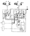
- an electronic unit 1 is actively connected to an electric motor 2 which is connected to a pump 3.
- the pump transports hydraulic fluid through a pipe 4 from a reservoir 5 for such a fluid to two solenoid valves 6A and 6B of the pressure control valve type having a return connection 7 to the tank 5.
- valve 6A is arranged for the brake actuators SA of the first bogie of the vehicle, while the other valve 6B is arranged for the brake actuators 8B of the second bogie of the vehicle, said actuators comprising disc brake linkages of the type application by spring and hydraulic loosening, known per se, the connections between the valve 6A and the actuators 8A on the one hand and the valve 68 and the actuators 88 on the other hand, being produced respectively by the lines 9A and 9B.
- each valve is electrically connected to a central unit 10, which can be actuated manually for example by means of a control lever.
- a pump 3 is driven by a motor 2 controlled by an electronic unit 1, to provide a constant hydraulic pressure.
- the hydraulic pressure delivered by each solenoid valve 6A and 6B is adjusted by means of a central unit 10 which regulates the current flowing in the solenoid of the valve considered, according to the braking requests.
- Two accumulators 13A and 13B are connected to line 4 and placed respectively at the inlet of valves 6A and 6B.
- they are of the hydropneumatic type.
- Each outlet pipe 9A and 98 has a calibrated orifice 14A and 14B. These pipes 9A and 98 are connected to the pipe 7 downstream of said orifice calibrated by a shunt 15A and 158. A non-return valve 16A and 16B is placed on said shunt and lets the fluid from the pipe 9A and 98, towards the line 4 but prevents movement of the fluid in the opposite direction.
- the different operating conditions of the hydraulic braking system have been described in said patent.
- the braking force is controlled by delivering hydraulic fluid under pressure regulated by the valves SA and 68.
- the hydraulic braking system is de-energized, the safety valve 12 establishes a connection between the lines 4 and 7 (the position of the valve 12 shown in the drawing) and the non-return valves 16A and 168 connect the actuators to the reservoir.
- the arrangement of the invention eliminates this drawback by giving a braking force which is adjusted to the load of the vehicle.
- a solenoid valve 17, supplied by line 4 and connected to the return line 7, is controlled by the central unit 10 so as to maintain at its output a hydraulic pressure which is inversely proportional to the load of the vehicle.
- a valve 18 connects the outlet of the valve 17 to the accumulator 20 through the calibrated orifice 19 when the power is turned on. It interrupts the connection when the power is turned off in order to prevent the flow of fluid from the accumulator 20 to the reservoir 5 through the valve 17.
- the purpose of the calibrated orifice 19 is to attenuate the oscillations in the hydraulic braking system when the accumulator 20 is filled and allow the valve 18 to close before a significant quantity of hydraulic fluid is admitted. evacuate from the accumulator in emergency braking.
- the accumulator 20 is connected to the lines 9A and 9B respectively by bidirectional valves 21A and 21B.
- the bidirectional valves 21A and 218 are controlled by the dominant pressure delivered either by the valves 6A and 6B, or by the accumulator 20.
- the electrical control of the hydraulic braking system is de-energized and the pressure delivered by the valves 6A and 6B drops.
- the pressure prevailing in the accumulator 20 then maintains in the actuators 8A and 88 a braking force adjusted to the momentary load of the vehicle.
- the actuators 8A and 8B are again supplied with the pressure delivered by 6A and 6B through bidirectional valves 21A and 218.
- a pressure sensor 22 is connected to the accumulator 20 for indication and measurement purposes but can also be used to control valves 17 and 18 of a type other than those used in the version shown and described below. after.
- valves 23A and 23B are arranged in parallel with the valves 6A and 21A and the valves 66 and 21B.
- valves 23A and 23B are pressure limiting valves preventing the pressure from exceeding a predetermined maximum value above which the valves are open to directly connect the accumulator to the pipe 7 and thus to the reservoir 5.
- valve 24 connecting the accumulator directly with the pipe 7 and thus towards the reservoir.
- the valve 24 must be manually controlled but can also include a calibrated orifice which automatically empties the accumulator 20 after a predetermined period, for example 15 minutes, if no hydraulic fluid is supplied through the valve 17 to the accumulator.
Landscapes
- Engineering & Computer Science (AREA)
- Transportation (AREA)
- Mechanical Engineering (AREA)
- Valves And Accessory Devices For Braking Systems (AREA)
- Braking Systems And Boosters (AREA)
- Braking Arrangements (AREA)
Priority Applications (1)
| Application Number | Priority Date | Filing Date | Title |
|---|---|---|---|
| AT86400854T ATE42510T1 (de) | 1985-04-22 | 1986-04-21 | Hydraulisches bremssystem fuer schienenfahrzeuge. |
Applications Claiming Priority (2)
| Application Number | Priority Date | Filing Date | Title |
|---|---|---|---|
| FR8506047 | 1985-04-22 | ||
| FR8506047A FR2580572B1 (fr) | 1985-04-22 | 1985-04-22 | Systeme de freinage hydraulique pour vehicules ferroviaires |
Publications (2)
| Publication Number | Publication Date |
|---|---|
| EP0200632A1 true EP0200632A1 (de) | 1986-11-05 |
| EP0200632B1 EP0200632B1 (de) | 1989-04-26 |
Family
ID=9318490
Family Applications (1)
| Application Number | Title | Priority Date | Filing Date |
|---|---|---|---|
| EP86400854A Expired EP0200632B1 (de) | 1985-04-22 | 1986-04-21 | Hydraulisches Bremssystem für Schienenfahrzeuge |
Country Status (5)
| Country | Link |
|---|---|
| US (1) | US4775191A (de) |
| EP (1) | EP0200632B1 (de) |
| AT (1) | ATE42510T1 (de) |
| DE (1) | DE3663010D1 (de) |
| FR (1) | FR2580572B1 (de) |
Cited By (1)
| Publication number | Priority date | Publication date | Assignee | Title |
|---|---|---|---|---|
| EP0363827A3 (de) * | 1988-10-05 | 1991-06-12 | Knorr-Bremse Ag | Drehgestellfahrzeug mit elektrohydraulischer Bremse und hydropneumatischer Abfederung |
Families Citing this family (3)
| Publication number | Priority date | Publication date | Assignee | Title |
|---|---|---|---|---|
| GB2344142B (en) | 1998-11-27 | 2003-01-22 | Lucas Ind Plc | Pump motor control in electro-hydraulic braking systems |
| DE102010005091B4 (de) * | 2010-01-18 | 2013-08-08 | Siemens Aktiengesellschaft | Bremsanordnung eines Schienenfahrzeugs |
| CN115743074B (zh) * | 2022-12-21 | 2026-03-10 | 中车制动系统有限公司 | 液压制动缸压力控制系统及其控制方法 |
Citations (6)
| Publication number | Priority date | Publication date | Assignee | Title |
|---|---|---|---|---|
| US2330739A (en) * | 1940-11-29 | 1943-09-28 | Transit Res Corp | Hydraulic braking system |
| DE2140781A1 (de) * | 1970-08-26 | 1972-03-02 | Westinghouse Brake and Signal Co Ltd, London | Bremsensteuervorrichtung |
| FR2210532A1 (de) * | 1972-12-13 | 1974-07-12 | Girling Ltd | |
| US3881785A (en) * | 1973-04-03 | 1975-05-06 | Knorr Bremse Gmbh | Load responsive air brake system for vehicles including a spring-loaded cylinder |
| GB1587405A (en) * | 1977-07-18 | 1981-04-01 | Dilltown Holdings Ltd | Braking systems |
| EP0089081A1 (de) * | 1982-03-16 | 1983-09-21 | SAB NIFE AB (reg. no. 556010-0058) | Hydraulisches Bremssystem für Fahrzeuge |
Family Cites Families (7)
| Publication number | Priority date | Publication date | Assignee | Title |
|---|---|---|---|---|
| US3178238A (en) * | 1963-08-26 | 1965-04-13 | Budd Co | Brake apparatus |
| DE2015799B2 (de) * | 1970-04-02 | 1977-03-17 | Knorr-Bremse GmbH, 8000 München | Bremsvorrichtung fuer schienenfahrzeuge |
| DE2622746A1 (de) * | 1976-05-21 | 1977-11-24 | Wabco Westinghouse Gmbh | Einrichtung zur bremskraftregelung von kraftfahrzeugen |
| SE7703171L (sv) * | 1977-03-21 | 1978-09-22 | Bromsregulator Svenska Ab | Hydrauliskt fordonsbromssystem |
| US4307916A (en) * | 1979-12-20 | 1981-12-29 | Tec Tran Corp. | Hydraulic braking system |
| SU1090599A2 (ru) * | 1982-10-05 | 1984-05-07 | Белорусский Ордена Трудового Красного Знамени Политехнический Институт | Электропневматическа тормозна система транспортного средства |
| SE447231B (sv) * | 1983-06-22 | 1986-11-03 | Sab Nife Ab | Bromssystem for ett relsfordon |
-
1985
- 1985-04-22 FR FR8506047A patent/FR2580572B1/fr not_active Expired
-
1986
- 1986-04-21 AT AT86400854T patent/ATE42510T1/de not_active IP Right Cessation
- 1986-04-21 DE DE8686400854T patent/DE3663010D1/de not_active Expired
- 1986-04-21 EP EP86400854A patent/EP0200632B1/de not_active Expired
-
1987
- 1987-08-10 US US07/086,228 patent/US4775191A/en not_active Expired - Fee Related
Patent Citations (6)
| Publication number | Priority date | Publication date | Assignee | Title |
|---|---|---|---|---|
| US2330739A (en) * | 1940-11-29 | 1943-09-28 | Transit Res Corp | Hydraulic braking system |
| DE2140781A1 (de) * | 1970-08-26 | 1972-03-02 | Westinghouse Brake and Signal Co Ltd, London | Bremsensteuervorrichtung |
| FR2210532A1 (de) * | 1972-12-13 | 1974-07-12 | Girling Ltd | |
| US3881785A (en) * | 1973-04-03 | 1975-05-06 | Knorr Bremse Gmbh | Load responsive air brake system for vehicles including a spring-loaded cylinder |
| GB1587405A (en) * | 1977-07-18 | 1981-04-01 | Dilltown Holdings Ltd | Braking systems |
| EP0089081A1 (de) * | 1982-03-16 | 1983-09-21 | SAB NIFE AB (reg. no. 556010-0058) | Hydraulisches Bremssystem für Fahrzeuge |
Cited By (1)
| Publication number | Priority date | Publication date | Assignee | Title |
|---|---|---|---|---|
| EP0363827A3 (de) * | 1988-10-05 | 1991-06-12 | Knorr-Bremse Ag | Drehgestellfahrzeug mit elektrohydraulischer Bremse und hydropneumatischer Abfederung |
Also Published As
| Publication number | Publication date |
|---|---|
| DE3663010D1 (en) | 1989-06-01 |
| US4775191A (en) | 1988-10-04 |
| ATE42510T1 (de) | 1989-05-15 |
| FR2580572A1 (fr) | 1986-10-24 |
| EP0200632B1 (de) | 1989-04-26 |
| FR2580572B1 (fr) | 1987-07-10 |
Similar Documents
| Publication | Publication Date | Title |
|---|---|---|
| EP1205369B1 (de) | Architektur eines hydraulischen Flugzeugbremssystems | |
| EP1404978B1 (de) | Hydraulikkreis für ein flugzeugbremssystem | |
| FR2624462A1 (fr) | Systeme de freinage antiblocage pour vehicule automobile | |
| EP1884432B1 (de) | Verfahren zur Steuerung einer Bremseinheit einer Seilbahn und Bremseinheit | |
| FR2471899A1 (fr) | Installation de freinage hydraulique avec un systeme antiblocage | |
| FR2548291A1 (fr) | Installation hydraulique comportant deux equipements utilisateurs d'energie hydraulique | |
| FR2602195A1 (fr) | Dispositif de freinage a regulation du glissement de freinage pour vehicule automobile | |
| FR2574358A1 (fr) | Circuit de commande de la pression auxiliaire d'un circuit de freinage | |
| FR2573710A1 (fr) | Dispositif de regulation de la pression dans un accumulateur de pression auxiliaire de freinage | |
| FR2629145A1 (fr) | Dispositif de commande d'un verin hydraulique a double effet | |
| EP0200632B1 (de) | Hydraulisches Bremssystem für Schienenfahrzeuge | |
| FR2660903A1 (fr) | Installation de freinage hydraulique a deux circuits avec systeme antiblocage et regulation antipatinage a l'entrainement. | |
| EP0275786A1 (de) | Bremskreis für Flugzeuge | |
| EP0238368B1 (de) | Speisesystem für Druckflüssigkeit | |
| FR2544268A1 (fr) | Procede et dispositif de securite pour l'attaque d'une valve de commande de pression dans une regulation automatique de l'effort de freinage en fonction de la charge | |
| FR2593757A1 (fr) | Systeme hydraulique de freinage | |
| CN216508301U (zh) | 一种轨道车辆的液压制动系统及轨道车辆 | |
| FR2593129A1 (fr) | Systeme de freinage a regulation du glissement. | |
| CH640792A5 (fr) | Dispositif de commande d'un ralentisseur electrique. | |
| EP2445766B1 (de) | Hydraulisches bremssystem mit hydraulischer unterstützung | |
| FR2600958A1 (fr) | Systeme de freinage hydraulique pour vehicule automobile | |
| FR2577875A1 (fr) | Installation de freinage a fluide sous pression pour vehicules | |
| FR2515592A1 (fr) | Installation de freinage pour remorques de vehicules automobiles | |
| CN210317949U (zh) | 一种多功能液压站 | |
| EP1827940B1 (de) | Bremsvorrichtung für ein industriefahrzeug |
Legal Events
| Date | Code | Title | Description |
|---|---|---|---|
| PUAI | Public reference made under article 153(3) epc to a published international application that has entered the european phase |
Free format text: ORIGINAL CODE: 0009012 |
|
| AK | Designated contracting states |
Kind code of ref document: A1 Designated state(s): AT BE CH DE GB IT LI LU NL SE |
|
| 17P | Request for examination filed |
Effective date: 19870121 |
|
| 17Q | First examination report despatched |
Effective date: 19880204 |
|
| ITF | It: translation for a ep patent filed | ||
| GRAA | (expected) grant |
Free format text: ORIGINAL CODE: 0009210 |
|
| AK | Designated contracting states |
Kind code of ref document: B1 Designated state(s): AT BE CH DE GB IT LI LU NL SE |
|
| PG25 | Lapsed in a contracting state [announced via postgrant information from national office to epo] |
Ref country code: SE Effective date: 19890426 Ref country code: NL Effective date: 19890426 |
|
| REF | Corresponds to: |
Ref document number: 42510 Country of ref document: AT Date of ref document: 19890515 Kind code of ref document: T |
|
| GBT | Gb: translation of ep patent filed (gb section 77(6)(a)/1977) | ||
| REF | Corresponds to: |
Ref document number: 3663010 Country of ref document: DE Date of ref document: 19890601 |
|
| NLV1 | Nl: lapsed or annulled due to failure to fulfill the requirements of art. 29p and 29m of the patents act | ||
| PLBE | No opposition filed within time limit |
Free format text: ORIGINAL CODE: 0009261 |
|
| STAA | Information on the status of an ep patent application or granted ep patent |
Free format text: STATUS: NO OPPOSITION FILED WITHIN TIME LIMIT |
|
| 26N | No opposition filed | ||
| PGFP | Annual fee paid to national office [announced via postgrant information from national office to epo] |
Ref country code: AT Payment date: 19930326 Year of fee payment: 8 |
|
| PGFP | Annual fee paid to national office [announced via postgrant information from national office to epo] |
Ref country code: GB Payment date: 19930414 Year of fee payment: 8 |
|
| PGFP | Annual fee paid to national office [announced via postgrant information from national office to epo] |
Ref country code: CH Payment date: 19930419 Year of fee payment: 8 |
|
| PGFP | Annual fee paid to national office [announced via postgrant information from national office to epo] |
Ref country code: DE Payment date: 19930423 Year of fee payment: 8 |
|
| ITTA | It: last paid annual fee | ||
| PGFP | Annual fee paid to national office [announced via postgrant information from national office to epo] |
Ref country code: LU Payment date: 19930503 Year of fee payment: 8 |
|
| PGFP | Annual fee paid to national office [announced via postgrant information from national office to epo] |
Ref country code: BE Payment date: 19930513 Year of fee payment: 8 |
|
| EPTA | Lu: last paid annual fee | ||
| PG25 | Lapsed in a contracting state [announced via postgrant information from national office to epo] |
Ref country code: LU Free format text: LAPSE BECAUSE OF NON-PAYMENT OF DUE FEES Effective date: 19940421 Ref country code: GB Effective date: 19940421 Ref country code: AT Effective date: 19940421 |
|
| PG25 | Lapsed in a contracting state [announced via postgrant information from national office to epo] |
Ref country code: LI Effective date: 19940430 Ref country code: CH Effective date: 19940430 Ref country code: BE Effective date: 19940430 |
|
| BERE | Be: lapsed |
Owner name: SAB NIFE Effective date: 19940430 Owner name: REGIE AUTONOME DES TRANSPORTS PARISIENS Effective date: 19940430 |
|
| GBPC | Gb: european patent ceased through non-payment of renewal fee |
Effective date: 19940421 |
|
| REG | Reference to a national code |
Ref country code: CH Ref legal event code: PL |
|
| PG25 | Lapsed in a contracting state [announced via postgrant information from national office to epo] |
Ref country code: DE Effective date: 19950103 |
|
| PG25 | Lapsed in a contracting state [announced via postgrant information from national office to epo] |
Ref country code: IT Free format text: LAPSE BECAUSE OF NON-PAYMENT OF DUE FEES;WARNING: LAPSES OF ITALIAN PATENTS WITH EFFECTIVE DATE BEFORE 2007 MAY HAVE OCCURRED AT ANY TIME BEFORE 2007. THE CORRECT EFFECTIVE DATE MAY BE DIFFERENT FROM THE ONE RECORDED. Effective date: 20050421 |