EP0200693A1 - Meeresanker zum Herablassen entlang einer geneigten Ebene - Google Patents
Meeresanker zum Herablassen entlang einer geneigten Ebene Download PDFInfo
- Publication number
- EP0200693A1 EP0200693A1 EP86850129A EP86850129A EP0200693A1 EP 0200693 A1 EP0200693 A1 EP 0200693A1 EP 86850129 A EP86850129 A EP 86850129A EP 86850129 A EP86850129 A EP 86850129A EP 0200693 A1 EP0200693 A1 EP 0200693A1
- Authority
- EP
- European Patent Office
- Prior art keywords
- anchor
- wing
- shank
- rope
- glide
- Prior art date
- Legal status (The legal status is an assumption and is not a legal conclusion. Google has not performed a legal analysis and makes no representation as to the accuracy of the status listed.)
- Granted
Links
- XLYOFNOQVPJJNP-UHFFFAOYSA-N water Substances O XLYOFNOQVPJJNP-UHFFFAOYSA-N 0.000 claims abstract description 27
- 241000935974 Paralichthys dentatus Species 0.000 claims abstract description 9
- 241000242541 Trematoda Species 0.000 claims abstract description 8
- 238000004873 anchoring Methods 0.000 claims description 14
- 230000033001 locomotion Effects 0.000 claims description 10
- 230000005484 gravity Effects 0.000 claims description 4
- 230000000717 retained effect Effects 0.000 claims description 3
- 239000002184 metal Substances 0.000 claims description 2
- 229910052751 metal Inorganic materials 0.000 claims description 2
- 230000000063 preceeding effect Effects 0.000 claims 2
- 230000000284 resting effect Effects 0.000 claims 1
- 238000000034 method Methods 0.000 description 3
- 230000008901 benefit Effects 0.000 description 2
- 230000003993 interaction Effects 0.000 description 2
- 239000003381 stabilizer Substances 0.000 description 2
- 239000000725 suspension Substances 0.000 description 2
- XEEYBQQBJWHFJM-UHFFFAOYSA-N Iron Chemical group [Fe] XEEYBQQBJWHFJM-UHFFFAOYSA-N 0.000 description 1
- 229910000831 Steel Inorganic materials 0.000 description 1
- 230000005540 biological transmission Effects 0.000 description 1
- 238000005266 casting Methods 0.000 description 1
- QYIYFLOTGYLRGG-GPCCPHFNSA-N cefaclor Chemical compound C1([C@H](C(=O)N[C@@H]2C(N3C(=C(Cl)CS[C@@H]32)C(O)=O)=O)N)=CC=CC=C1 QYIYFLOTGYLRGG-GPCCPHFNSA-N 0.000 description 1
- 229960005361 cefaclor Drugs 0.000 description 1
- 230000000694 effects Effects 0.000 description 1
- 238000012986 modification Methods 0.000 description 1
- 230000004048 modification Effects 0.000 description 1
- 238000011017 operating method Methods 0.000 description 1
- 239000007787 solid Substances 0.000 description 1
- 239000010959 steel Substances 0.000 description 1
- 229920002994 synthetic fiber Polymers 0.000 description 1
Images

Classifications
-
- B—PERFORMING OPERATIONS; TRANSPORTING
- B63—SHIPS OR OTHER WATERBORNE VESSELS; RELATED EQUIPMENT
- B63B—SHIPS OR OTHER WATERBORNE VESSELS; EQUIPMENT FOR SHIPPING
- B63B21/00—Tying-up; Shifting, towing, or pushing equipment; Anchoring
- B63B21/24—Anchors
- B63B21/38—Anchors pivoting when in use
- B63B21/40—Anchors pivoting when in use with one fluke
-
- B—PERFORMING OPERATIONS; TRANSPORTING
- B63—SHIPS OR OTHER WATERBORNE VESSELS; RELATED EQUIPMENT
- B63B—SHIPS OR OTHER WATERBORNE VESSELS; EQUIPMENT FOR SHIPPING
- B63B21/00—Tying-up; Shifting, towing, or pushing equipment; Anchoring
- B63B21/24—Anchors
- B63B21/26—Anchors securing to bed
- B63B2021/262—Anchors securing to bed by drag embedment
Definitions
- the present invention relates to anchors, and more specifically to sea anchors.
- an anchor of this kind is so arranged, when being Lowered to the bottom, as to follow an oblique or inclined path.
- anchoring with the help of a conventional anchor takes place in such a way that the anchor is deployed whilst the boat or vessel is still some distance away from the intended anchoring place.
- the anchor sinks more or Less straight down to the bottom, whilst the boat continues on its way.
- the anchor drags for a few moments before gripping, whereupon the boat is anchored by means of the anchor rope or anchor chain which extends obliquely outwards and down to the anchor Lying and fixed on the bottom.
- the object of the invention is thus to simplify the anchoring procedure by making it possible to position the boat first at the intended anchoring place and then to drop the anchor, said anchor being executed in such a way that it will not drop straight down through the water but will glide along a fairly flat, inclined plane away from the boat. Once it has landed on the bottom it can be made to drag and to take a grip by being operated for the entire period from a stationary boat lying at the intended anchoring place.
- Previously discLosed in, for example, Swedish Patent 344720 and US Patent 3,611,974 is the principle of sending out anchoring arrangements from a given point in different directions and obliqueLy downwards towards the bottom.
- the devices concerned here are intended primarily for anchoring buoys with the help of two or more weights Lying on the bottom; these are not, therefore, in the form of gripping anchors.
- the weights consist of cylindrical bodies executed as small aeroplanes with wings and stabilizers, and it is possible with the help of these devices to cause the body to glide obtiquely down towards the bottom, albeit at a rather steep glide path of about 450 .
- the object of this invention is, on the other hand, to propose a true gripping anchor which also follows an oblique path at an angle to the bottom, but which is a good deal flatter than the glide path of the previously disclosed arrangement, to the extent that the path exhibits a so-called gliding ratio of between 1:4 and 1:5, that is to say the path is inclined towards the bottom at an angle of the order of 12-15°.
- This means that the anchor can be deployed for a considerable distance from the boat before it Lands on the bottom; if the boat has about 4-5 metres of water beneath the keel, then the anchor can be made to find a secure grip at a distance of 15 to 25 m from the boat, thereby providing advantageous anchoring conditions.
- the performance of the anchor in accordance with the invention is strikingly obvious from the very start; this is no Lightweight object, but rather a solid iron structure which, in accordance with the invention, is so executed as to exhibit, in addition to its ability to glide, an ability to find a grip on the bottom apparently rapidly and effectively as the anchor cable behind the anchor is tensioned.
- the principle by which the 'gLiding anchor' in accordance with the invention is able to exhibit such an ability to glide along a flat path through the water is easily appreciated from a comparison of the aerodynamic and hydrodynamic parameters: in principle the anchor in accordance with the invention glides through the water in the same way as a glider aircraft glides through the air, and both are subject to the same rules and formulae in respect of Lift and drag.
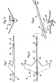
- FIG. 1 to 3 in the drawing thus portray a side, plan and front view respectively of an anchor executed in accordance with the invention, with all of the Figures being drawn in a highly schematic manner and in such a way that they illustrate the principle of the invention as clearly as possible.
- Fig. 4 is a side view, similarly schematic in nature, of the anchor in accordance with the invention and shows it in an initial phase of its engagement with the bottom of the sea or the bed of a Lake.
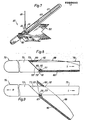
- FIG. 5 is a perspective view of a practical embodiment of the anchor in accordance with the invention and shows it viewed at an angle from the front whilst it is gliding forwards through the water.
- Fig. 6 shows, similarly as a perspective view, the anchor in accordance with Fig. 5 once it has landed on the bottom and whilst it is being dragged into engagement with it.
- Fig. 7 is a schematic representation on a smaller scale of a somewhat modified anchor in accordance with Figs. 5 and 6 viewed from the side in a suspended position.
- Figs. 8 and 9 are detailed sections through the central part of a further modified anchor in the gliding attitude, whilst Fig. 9 shows the same part of the anchor in the engagement position.
- FIGs. 1 to 3 thus schematically illustrate an anchor 10 in accordance with the invention, said anchor consisting of - if we are to apply the traditional designations for parts of anchors - an anchor shank 15 in the form of a straight bar or rail constituting the crown 12 of the anchor at the front and the head 14 of the anchor at the rear. Attached to the head is a shackle or tube 16 for the connection of an anchor rope 18.
- the arms of the anchor project from the shank 15 behind the crown 12 running transversely across the shank, and in accordance with the invention these arms have the form of a continuous wing 20, which is now described in greater detail.
- the former is provided with two centrally arranged, longitudinal bars or ribs 28 (see in particular Figs. 1 and 3) which between them accommodate the shank 15.
- This is pivotally attached to the bars by means of an articulated link 30, for example in the form of a bolt or pin.
- the pair of arms or the wing 20 is thus pivotally attached to the anchor shank 15 for a purpose which will be described Later.
- the schematically iLLustrated anchor in accordance with the invention will be seen to present the appearance of a stylized aeroplane, in which the shank 15 corresponds to the fuselage and the pair of arms 20 corresponds to the wing of the aeroplane. This will be seen to be noticeably swept back (see Fig. 2) and to exhibit a marked 'V' form (see Fig. 3).
- the trailing edge of the wing exhibits, as may also be clearly seen, an interrupted plane profile, and the central part of the wing is extended rearwards to form a point 26 resulting in a triangular, spade-shaped part 25, as may be appreciated from Fig. 2 in particular.
- This part 25 corresponds to an anchor fluke on a conventional anchor, and the actual tip 26 thus constitutes a point.
- the size and position of the anchor shank 15 in relation to the pair of arms or the wing 20 is matched to the principal forces acting upon the anchor, which, as in the case of an aircraft, consist of a resulting Lifting force acting on the wing 20, a resulting drag force acting on the anchor as a whole and countering the forward gliding motion, plus the weight of the anchor, said forces balancing one another out precisely as in an aircraft.
- the drag force includes a component for the anchor rope 18 which the anchor draws with it through the water and which also stabilizes the anchor as it glides forwards.
- the anchor rope 18 consists preferably of a strip of modern, synthetic material such as is described in patent 8300513-2. A strip of this kind is extremely strong and presents fairly low resistance to being pulled forwards through the water.
- the anchor in accordance with the invention will glide forwards in a stable manner along an essentially rectilinear path, the inclination of which is determined primarily by the detailed execution of the anchor wing 20. It has been found to be possible in practice to achieve fairly flat glide paths, especially if the aforementioned, strip-shaped type of anchor rope 18 is used. As already. mentioned, gliding ratios of between 1:4 and 1:5 have been achieved.
- the anchor wing 20 is connected to the shank 15 by means of an articulated link 30. This is situated at or close to the Leading edge of the wing (see Figs. 1 and 2), which means that the wing 20 as a whole can be folded downwards in relation to the shank 15,
- the pointed rear part 25 of the wing will dig into the bottom in the same way as occurs with the pivotally attached anchor fluke of a conventional anchor.
- Fig. 4 represents schematically the initial phase of the gripping procedure for the anchor.
- the shank 15 When a force P is applied to the anchor rope 18, the shank 15 will rise from the wing 20 as it pivots about the articulated link 30.
- the position of the Latter in relation to the part at the very front or the tip of the Leading edge of the arrow-shaped wing is, for example, such that the Leading edge strikes the under side of the shank 15 at a contact point 31. Further relative movement between the shank and the wing is prevented in this way, and the two elements form with one another an obtuse angle y of appropriate size, such that the rear pointed part of the wing or the anchor fluke 25 is caused to start to dig down, as illustrated in Fig. 4.
- the swept back tips 25' of the wing wiLL also act as anchor flukes with points 26' and wiLL start to dig down, and the entire device will soon be securely anchored to the bottom.
- the anchor in accordance with the invention has a modified design in order to give it the ability to glide through the water, in addition to which the design of the wing part of the anchor makes the anchor self-stabilizing as it glides (due mainly to the 'V'-shape of the wing), so that the anchor will always Land 'on an even keeL', as it were, on the bottom. Accordingly no canting device, Like the usual anchor shank, is required, and similarly there is no need for the duplication of the moving anchor flukes which is essential in previousLy disclosed anchors if these are to have the ability to grip in whatever position they may arrive on the bottom.
- Fig. 5 shows a perspective view of a practical embodiment of a gliding anchor 40 in accordance with the invention on its way through the water.
- This embodiment harmonizes fully with that which is represented only schematically in the previous Figures and includes a wing 50.
- an anchor shank 45 is thus supported between the side arms by means of the articulated Link 60, and the shank is terminated at the front by an enlarged part 42 constituting the crown of the anchor.
- the anchor shank 45 extends from the crown 42 rearwards towards a head 44, to the end of which a shackle or a tube 46 is attached.
- This is connected to an anchor rope 48 in the form of the previously described strip.
- the wing executed as a single piece, which in this way corresponds to the pair of arms of the conventional anchor, in this case exhibits a central, shallow groove 52 which extends rearwards from the arms 58 and constitutes a prolongation of the space between these.
- the wing exhibits a central part 55 which narrows to the rear and constitutes the flukes of the anchor with a tip or point 56 situated at the end of said groove 52.
- Fig. 5 thus illustrates the anchor assembly in accordance with the invention as it glides through the water towing the anchor rope 48 behind it.
- Fig. 6 shows the anchor immediateLy after having landed on the bottom and after a tractive force has been applied to the enchor rope.
- the rearward motion of the anchor is counteracted immediately by the flukes 55 of the wing 50 finding a grip on the bottom or in some other way being arrested by an obstacle.
- the result of this grip being established is for the anchor shank 45 to rise immediately out of the groove 52 and to pivot about the articulated link 60 through a certain angle ⁇ ' , which is restricted, for example, through contact between the shank and the rear edge of the bridge piece 59.
- the Leading edge of the Latter may, furthermore, be utilized in the gliding attitude as a stop against the crown 42, at the same time as the anchor shank or the 'fuselage' 45 rests with its under side against the bottom of the groove 52.
- the gripping position shown in Fig. 6 as the anchor continues to dig down may also be extended to provide a grip at the pointed trailing edges 56' of the wing at the ends 55' of the wing, which in this case, too constitute additional flukes on the anchor 40.
- the anchor in accordance with the invention also exhibits all the characteristics of a conventional anchor with regard to its ability to find a grip and to be retained in the bottom of the sea or on the bed of a lake.
- the anchor in accordance with the invention is self-stabilizing, that is to say it can be dropped into the water in more or less any attitude, whereupon it will right itself on its way down to the bottom and will start its forward glide. It is not possible in practice, however, for the anchor to be handled in this way,-.because it would Lose far too much 'height' in relation to the bottom, with the associated risk of an excessively short gliding distance.
- the anchor should, instead, be deployed in an approximately horizontal attitude so that it can immediately adopt its 'gLiding attitude' and begin its glide, in conjunction with which the anchor is, of course, pointed in the direction of the desired place of anchoring.
- the anchor More often than not, however, it may prove difficult to deploy the anchor in this way simply by dropping it into the water Lying horizontally, especially if the boat has quite a high freeboard.
- the possibility should, therefore, be available for Lowering the anchor gently down into the water Lying in the correct attitude, or more precisely with the wing of the anchor in an attitude such that it will immediately adopt the appropriate angle of attack at the start of its glide.
- the anchor it is, of course, preferable for the anchor to be capable of being Lowered down gently into the water using the anchor rope, although it will clearly be necessary to take certain precautions since the anchor in accordance with the invention will, in the-case of the embodiment illustrated, hang straight down from the end of the rope.
- Fig. 7 The anchor 40' illustrated here corresponds in aLL essential respects to the anchor 40 in accordance with Figs. 5 and 6, although it will be appreciated that a LongitudinaL slot 47 is formed in the shank 45' of the anchor 40'.
- the width of the slot matches the dimensions of the transverse bolt of the tube 46, so that the tube with its anchor rope 48 attached is able to slide along the slot 47 along most of the length of the shank 45' and as far forwards as a point immediately behind the articulated Link 60' of the anchor.
- the slot 47 exhibits an upward deflection 49 in relation to the shank, as may be appreciated clearly from Fig. 7.
- the suspension arrangement described is, on the whole, arranged in such a way that the anchor wiLL hang down with the wing 50' LargeLy horizontal and adopting an appropriate attitude such that, after having been deployed in a straight down direction, it wiLL adopt a gliding attitude as quickly as possible.
- the shank 45' will faLL and will adopt its normal position in accordance with Fig. 5.
- the tube 46 is able to slide back in the slot 47, since the tractive force applied to its bolt wiLL displace the Latter from the deflection 49 and the tube together with its anchor rope wiLL adopt its normal position at the rear end of the anchor.
- the temporary suspension of the anchor in the attitude illustrated in Fig. 7, that is to say for the purpose of Lowering it gently down into the water in order to achieve the quickest possible start of the gliding motion of the anchor, can also be achieved by means other than those described above.
- the anchor rope may, for example, be attached to the end of the anchor in a normal manner, for instance as shown in Figs. 5 and 6, although it is possible at the front of the anchor shank, approximately at the position of the deflection 49 in the slot in accordance with F ig. 7 described above, to arrange a hook device on the shank for the temporary attachment of the anchor rope strip.
- the hook device is so executed and arranged for this purpose that the strip will remain suspended from the hook when in a position in accordance with Fig.
- Fig. 8 thus represents schematically a central vertical section through an anchor 70 which harmonizes in its principal characteristics with the anchor 40 described previously, but the wing of which consists of a robust sheet of steel cut into a straight flat form and bent in a single direction at the centre, with arms welded in position on the upper side.
- the anchor 70 thus consists, as before, of an anchor shank 75 with a front crown 72 and a wing 80 in accordance with the above, a central section through which is shown in Figs. 8 and 9, together with arms 88 which, as already mentioned, are welded in position on the upper. side of the wing, one to either side of the shank.
- the arms 88 are attached to a bridge piece 89 at the top and towards the front.
- the anchor 70 exhibits the same general configuration as the anchor 40 in accordance with Figs. 5 and 6.
- a heel 87 is attached at the Leading edge of the central section of the wing 80, said heel being the same width as the shank 75 and having more or less the same cross-sectional form shown in Figs. 8 and 9.
- the anchor shank 75 is provided with a corresponding recess 77 into which the heel 87 fits, and in the normal attitude or the gliding attitude of the anchor, the anchor shank and the wing will interact in the manner illustrated in Fig. 8.
- the trailing edge of the Lower part of the anchor crown 72 is inclined along a plane 73, as shown in Fig. 8.
- the angle of inclination is such that, at the same time as the extreme position is reached, that is to say when the upper side of the shank comes into contact with the contact surface 92 on the bridge piece 89, the inclined surface 73 will also make contact with a corresponding surface 81 along the leading edge of the central section of the wing 80.
- This surface 81 lies on the same plane as the plane 93 of the leading edge of the arms 88 and the bridge piece 89, and as will have been appreciated from the foregoing, the edge 90 of the articulated Link will be present at the upper end of said leading edge surface 81 of the wing.
- the aforementioned locking heel 87 on the wing is also present at this point.
- the anchor in accordance with Figs. 8 and 9 functions, as has already been mentioned, in precisely the same fashion as previously described in conjunction with the other embodiments of the anchor, in which case the anchor shank 75 and the wing 80 interact in such a way in both the gliding attitude and the digging attitude that all necessary transmission of force between these principal component parts of the anchor takes place in an effective fashion through the necessary degree of interaction between the contact surfaces.
- the anchor shank 75 is thus prevented in this way from moving in the direction indicated by the arrow L in relation to the wing 80.
- the heel 87 should preferably be executed in such a way that it will permit the anchor shank to be withdrawn only if a certain level of friction is overcome, which additionally contributes to the anchor components not being separated unintentionally. It is of considerable benefit if, on the other hand, as has already been mentioned, the anchor is capable of being dismantled easily for stowing on board.
Landscapes
- Chemical & Material Sciences (AREA)
- Engineering & Computer Science (AREA)
- Combustion & Propulsion (AREA)
- Mechanical Engineering (AREA)
- Ocean & Marine Engineering (AREA)
- Piles And Underground Anchors (AREA)
- Road Signs Or Road Markings (AREA)
- Road Paving Structures (AREA)
- Other Liquid Machine Or Engine Such As Wave Power Use (AREA)
- Bridges Or Land Bridges (AREA)
Applications Claiming Priority (2)
| Application Number | Priority Date | Filing Date | Title |
|---|---|---|---|
| SE8502187 | 1985-05-03 | ||
| SE8502187A SE447723C (sv) | 1985-05-03 | 1985-05-03 | Sjoeankare anordnat foer nedsaenkning laengs en lutande bana |
Publications (2)
| Publication Number | Publication Date |
|---|---|
| EP0200693A1 true EP0200693A1 (de) | 1986-11-05 |
| EP0200693B1 EP0200693B1 (de) | 1988-11-23 |
Family
ID=20360071
Family Applications (1)
| Application Number | Title | Priority Date | Filing Date |
|---|---|---|---|
| EP86850129A Expired EP0200693B1 (de) | 1985-05-03 | 1986-04-14 | Meeresanker zum Herablassen entlang einer geneigten Ebene |
Country Status (7)
| Country | Link |
|---|---|
| US (1) | US4704982A (de) |
| EP (1) | EP0200693B1 (de) |
| DE (1) | DE3661252D1 (de) |
| DK (1) | DK161626C (de) |
| FI (1) | FI87908C (de) |
| NO (1) | NO172104C (de) |
| SE (1) | SE447723C (de) |
Cited By (2)
| Publication number | Priority date | Publication date | Assignee | Title |
|---|---|---|---|---|
| US4831952A (en) * | 1986-10-24 | 1989-05-23 | Dumison Marine Pty. Ltd. | Anchor |
| US5829379A (en) * | 1994-07-21 | 1998-11-03 | Von Spies; Rudiger | Plate anchor |
Families Citing this family (4)
| Publication number | Priority date | Publication date | Assignee | Title |
|---|---|---|---|---|
| NL9202083A (nl) * | 1992-12-01 | 1994-07-01 | Vrijhof Ankers Beheer Bv | Ankervloei. |
| MX2016012539A (es) | 2014-03-27 | 2017-05-04 | Intermoor Inc | Sistemas de ancla enclavados por gravedad dirigibles activamente y metodos para su uso. |
| CN110481710B (zh) * | 2019-09-24 | 2025-02-18 | 东营鑫奥船舶设备制造有限公司 | 一种滑槽式三角锚 |
| US11566393B2 (en) * | 2019-12-11 | 2023-01-31 | Keith Holtman | Land anchor |
Citations (5)
| Publication number | Priority date | Publication date | Assignee | Title |
|---|---|---|---|---|
| US1974933A (en) * | 1933-03-21 | 1934-09-25 | Taylor Geoffrey Ingram | Anchor |
| GB1100518A (en) * | 1966-11-21 | 1968-01-24 | Georges Eugene Dial | Improvements in or relating to marine anchors |
| US3611974A (en) * | 1969-07-16 | 1971-10-12 | Honeywell Inc | Gliding anchors |
| SE344720B (de) * | 1970-10-30 | 1972-05-02 | Honeywell Inc | |
| US4397256A (en) * | 1979-06-01 | 1983-08-09 | Peter Bruce | Anchors |
Family Cites Families (5)
| Publication number | Priority date | Publication date | Assignee | Title |
|---|---|---|---|---|
| US2480188A (en) * | 1946-11-04 | 1949-08-30 | Thomas R Gardiner | Stop device for anchor shanks |
| US2722191A (en) * | 1952-01-28 | 1955-11-01 | Olaf H Johnson | Boat anchor |
| US3946695A (en) * | 1975-04-28 | 1976-03-30 | Honeywell Inc. | Self-deploying multiple anchor mooring systems |
| JPS60121183A (ja) * | 1983-12-03 | 1985-06-28 | Sojiro Nakamura | 錨構成体 |
| US4523539A (en) * | 1983-12-15 | 1985-06-18 | Granger Gerald M | Boat anchor |
-
1985
- 1985-05-03 SE SE8502187A patent/SE447723C/sv not_active IP Right Cessation
-
1986
- 1986-04-08 NO NO861350A patent/NO172104C/no unknown
- 1986-04-11 US US06/851,030 patent/US4704982A/en not_active Expired - Fee Related
- 1986-04-11 DK DK165486A patent/DK161626C/da not_active IP Right Cessation
- 1986-04-14 EP EP86850129A patent/EP0200693B1/de not_active Expired
- 1986-04-14 DE DE8686850129T patent/DE3661252D1/de not_active Expired
- 1986-05-12 FI FI861982A patent/FI87908C/fi not_active IP Right Cessation
Patent Citations (5)
| Publication number | Priority date | Publication date | Assignee | Title |
|---|---|---|---|---|
| US1974933A (en) * | 1933-03-21 | 1934-09-25 | Taylor Geoffrey Ingram | Anchor |
| GB1100518A (en) * | 1966-11-21 | 1968-01-24 | Georges Eugene Dial | Improvements in or relating to marine anchors |
| US3611974A (en) * | 1969-07-16 | 1971-10-12 | Honeywell Inc | Gliding anchors |
| SE344720B (de) * | 1970-10-30 | 1972-05-02 | Honeywell Inc | |
| US4397256A (en) * | 1979-06-01 | 1983-08-09 | Peter Bruce | Anchors |
Cited By (2)
| Publication number | Priority date | Publication date | Assignee | Title |
|---|---|---|---|---|
| US4831952A (en) * | 1986-10-24 | 1989-05-23 | Dumison Marine Pty. Ltd. | Anchor |
| US5829379A (en) * | 1994-07-21 | 1998-11-03 | Von Spies; Rudiger | Plate anchor |
Also Published As
| Publication number | Publication date |
|---|---|
| SE447723B (sv) | 1986-12-08 |
| NO861350L (no) | 1986-11-04 |
| NO172104B (no) | 1993-03-01 |
| FI87908C (fi) | 1993-03-10 |
| EP0200693B1 (de) | 1988-11-23 |
| DE3661252D1 (en) | 1988-12-29 |
| SE447723C (sv) | 1989-10-16 |
| NO172104C (no) | 1993-06-09 |
| DK161626C (da) | 1992-01-13 |
| DK161626B (da) | 1991-07-29 |
| FI87908B (fi) | 1992-11-30 |
| FI861982A7 (fi) | 1986-11-04 |
| DK165486D0 (da) | 1986-04-11 |
| DK165486A (da) | 1986-11-04 |
| FI861982A0 (fi) | 1986-05-12 |
| SE8502187D0 (sv) | 1985-05-03 |
| SE8502187L (de) | 1986-11-04 |
| US4704982A (en) | 1987-11-10 |
Similar Documents
| Publication | Publication Date | Title |
|---|---|---|
| US4706595A (en) | Anchor | |
| US4831952A (en) | Anchor | |
| US5138967A (en) | Marine anchor | |
| US4869193A (en) | Anchor | |
| EP0200693B1 (de) | Meeresanker zum Herablassen entlang einer geneigten Ebene | |
| US4248171A (en) | Anchor handling and securing assembly | |
| US5095839A (en) | Stabilizer for boats and the like | |
| US4763943A (en) | Crane hook | |
| US3022762A (en) | Anchor | |
| US3766877A (en) | Mooring anchor | |
| US4905622A (en) | Marine anti-roll device | |
| US4479452A (en) | Anchor handling and storage device | |
| US4972793A (en) | Anchor | |
| US2869503A (en) | Folding anchor | |
| CN214001971U (zh) | 一种组合式防撞船锚 | |
| US2681631A (en) | Anchor | |
| AU594800B2 (en) | Improved anchor | |
| JPS5855115Y2 (ja) | 係維掃海具 | |
| JP2005319820A (ja) | 折り畳みセールの構造 | |
| US20040154521A1 (en) | Folding anchor | |
| US3292565A (en) | Anchor apparatus | |
| AU734845B2 (en) | Anchor | |
| JPS62110591A (ja) | アンカ− | |
| GB2183580A (en) | Anchor | |
| US3379160A (en) | Anchor construction |
Legal Events
| Date | Code | Title | Description |
|---|---|---|---|
| PUAI | Public reference made under article 153(3) epc to a published international application that has entered the european phase |
Free format text: ORIGINAL CODE: 0009012 |
|
| AK | Designated contracting states |
Kind code of ref document: A1 Designated state(s): DE FR GB IT |
|
| 17P | Request for examination filed |
Effective date: 19870108 |
|
| 17Q | First examination report despatched |
Effective date: 19870828 |
|
| GRAA | (expected) grant |
Free format text: ORIGINAL CODE: 0009210 |
|
| ITF | It: translation for a ep patent filed | ||
| AK | Designated contracting states |
Kind code of ref document: B1 Designated state(s): DE FR GB IT |
|
| REF | Corresponds to: |
Ref document number: 3661252 Country of ref document: DE Date of ref document: 19881229 |
|
| ET | Fr: translation filed | ||
| PLBE | No opposition filed within time limit |
Free format text: ORIGINAL CODE: 0009261 |
|
| STAA | Information on the status of an ep patent application or granted ep patent |
Free format text: STATUS: NO OPPOSITION FILED WITHIN TIME LIMIT |
|
| 26N | No opposition filed | ||
| ITTA | It: last paid annual fee | ||
| PGFP | Annual fee paid to national office [announced via postgrant information from national office to epo] |
Ref country code: GB Payment date: 19940420 Year of fee payment: 9 Ref country code: FR Payment date: 19940420 Year of fee payment: 9 |
|
| PGFP | Annual fee paid to national office [announced via postgrant information from national office to epo] |
Ref country code: DE Payment date: 19940517 Year of fee payment: 9 |
|
| PG25 | Lapsed in a contracting state [announced via postgrant information from national office to epo] |
Ref country code: GB Effective date: 19950414 |
|
| GBPC | Gb: european patent ceased through non-payment of renewal fee |
Effective date: 19950414 |
|
| PG25 | Lapsed in a contracting state [announced via postgrant information from national office to epo] |
Ref country code: FR Effective date: 19951229 |
|
| PG25 | Lapsed in a contracting state [announced via postgrant information from national office to epo] |
Ref country code: DE Effective date: 19960103 |
|
| REG | Reference to a national code |
Ref country code: FR Ref legal event code: ST |
|
| PG25 | Lapsed in a contracting state [announced via postgrant information from national office to epo] |
Ref country code: IT Free format text: LAPSE BECAUSE OF NON-PAYMENT OF DUE FEES;WARNING: LAPSES OF ITALIAN PATENTS WITH EFFECTIVE DATE BEFORE 2007 MAY HAVE OCCURRED AT ANY TIME BEFORE 2007. THE CORRECT EFFECTIVE DATE MAY BE DIFFERENT FROM THE ONE RECORDED. Effective date: 20050414 |