EP0200699A2 - Vorrichtung für die Zufuhr von Flüssigkeit zu Werkzeugen für das Zerkleinern von hartem Material - Google Patents
Vorrichtung für die Zufuhr von Flüssigkeit zu Werkzeugen für das Zerkleinern von hartem Material Download PDFInfo
- Publication number
- EP0200699A2 EP0200699A2 EP86850146A EP86850146A EP0200699A2 EP 0200699 A2 EP0200699 A2 EP 0200699A2 EP 86850146 A EP86850146 A EP 86850146A EP 86850146 A EP86850146 A EP 86850146A EP 0200699 A2 EP0200699 A2 EP 0200699A2
- Authority
- EP
- European Patent Office
- Prior art keywords
- tool
- control valve
- nozzle
- fluid
- tools
- Prior art date
- Legal status (The legal status is an assumption and is not a legal conclusion. Google has not performed a legal analysis and makes no representation as to the accuracy of the status listed.)
- Granted
Links
Images

Classifications
-
- E—FIXED CONSTRUCTIONS
- E21—EARTH OR ROCK DRILLING; MINING
- E21C—MINING OR QUARRYING
- E21C35/00—Details of, or accessories for, machines for slitting or completely freeing the mineral from the seam, not provided for in groups E21C25/00 - E21C33/00, E21C37/00 or E21C39/00
- E21C35/18—Mining picks; Holders therefor
- E21C35/187—Mining picks; Holders therefor with arrangement of fluid-spraying nozzles
-
- E—FIXED CONSTRUCTIONS
- E21—EARTH OR ROCK DRILLING; MINING
- E21C—MINING OR QUARRYING
- E21C35/00—Details of, or accessories for, machines for slitting or completely freeing the mineral from the seam, not provided for in groups E21C25/00 - E21C33/00, E21C37/00 or E21C39/00
- E21C35/22—Equipment for preventing the formation of, or for removal of, dust
- E21C35/23—Distribution of spraying-fluids in rotating cutter-heads
Definitions
- the present invention relates to a device for supplying fluid at tools mounted in sockets in such a way that they are not axially movable, said tools being used to break solid materials, e g coal, and that a nozzle is arranged adjacent to the tool, said nozzle being related to a control valve that is arranged to supply fluid to the nozzle when a working tool is subjected to a counter-acting force.
- a control valve that is arranged to supply fluid to the nozzle when a working tool is subjected to a counter-acting force.
- the devices are arranged in such a way that fluid is supplied only when a working tool is charged axially.
- Devices of that kind are previously known from DE-A-2854307, DE-A-3307895 and EP-A-10534.
- the tool is arranged to be displaced rearwardly in axial direction during work, said axial displacement being used to control the fluid supply to the nozzle.
- An aim of the present invention is to design the device in such a way that the counter-acting force on-the tool can be used for control of the fluid supply without requiring an axial displacement of the tool in the socket.
- a tool 10 for breaking solid material e g coal
- the socket 11 is welded to a portion 12 of a machine for breaking solid materials, e g a cutting head or a cutting roller.
- Adjacent the tool 10 is a nozzle 13 arranged in the socket 11.
- the nozzle 13 has such a direction that a fluid jet discharged from the nozzle is directed somewhat in front of the tip of the tool 10.
- the nozzle 13 is connected to a control valve 14, that via a boring 15 in the valve is in connection with a not shown fluid source.
- a control valve 14 that via a boring 15 in the valve is in connection with a not shown fluid source.
- fluid flows under high pressure from the boring 15, passes the valve body 16 and enters an annular space 17 -n the control valve 16. From that space the fluid flows to the nozzle 13 via a boring 18.
- the tool 10 is rotatably mounted in a sleeve 19, that via a locking pin 20 is secured in the socket 11.
- the tool 10 is also arranged, via a flange 21, to bear against the frontal end surface 22 of the sleeve 19.
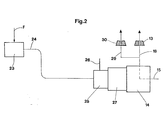
- the tool 10 is subjected to a rearwardly directed force F in the direction of the arrow P. Said force generates a compression strain in the sleeve 19.
- Sensor means in the shape of strain gauges 23 are secured to the sleeve 19 in such a way that they generate a control signal when a compression strain is present in the sleeve 19.
- This control signal is via a cabel 24 transmitted to an amplifier 25, that via a wire 26 is connected to a not shown voltage source.
- the amplified control signal from the amplifier is transmitted to an electromagnet 27, that displaces an operating rod 28 that is in engagement with the valve body 16, said displacement causing the valve body 16 to raise from its seat.
- the sensor means 23 of the control valve 14 is thus arranged to generate, in respect of the force F, pulses that opens the control valve 14.
- the strain gauges 23 are arranged in an interior and an exterior recess in the sleeve 19. Said recesses are filled with e g a rubber material 31 and 32 respectively to protect the gauges. Due to the fact that the tool is not axially movable in the socket said tool always bear against the socket. This prevents particles to enter between tool and socket, such entering would affect the rotating of the tool negatively. The rotating is important in order to have a uniform wearing of the tool tip.
- each of the nozzles 13 can have its own control valve 14. However, it seems more convinient to arrange the nozzles 13 in groups and give each group a control valve 14. This alternative is from economic point of view favourable due to the fact that fewer control valves and sensor means are required. Said alternative is illustrated in the figures showing fluid flowing from the space 17 via the borings 18, 29 to the nozzles 13, 30, said nozzle 30 being arranged in attachment to a not shown tool.
- control valve 14 of those sensor means 23 that sense the force F acting on a first tool 10 can be arranged to supply fluid to a second tool that is subsequent the first tool in the working order.
- the control valve 14 is shut there is a time delay because of damping so that the subsequent tool has time to leave its engagement with the material before the fluid supply to the last-mentioned tool is shut off.
- the invention is disclosed in connection with rotatably mounted tools it can of course be used for non-rotatably mounted tools.
- the nozzles instead of in front of the tool as is shown in Fig. 1, can be arranged behind the tool or both behind and in front of the tool.
- the fluid preferably flows from the space 17 in Fig. 1 to the frontal nozzle via the boring 18 and to the rear nozzle via the boring 29.
Landscapes
- Engineering & Computer Science (AREA)
- Mining & Mineral Resources (AREA)
- Mechanical Engineering (AREA)
- Life Sciences & Earth Sciences (AREA)
- General Life Sciences & Earth Sciences (AREA)
- Geochemistry & Mineralogy (AREA)
- Geology (AREA)
- Disintegrating Or Milling (AREA)
- Cutting Tools, Boring Holders, And Turrets (AREA)
- Earth Drilling (AREA)
- Auxiliary Devices For Machine Tools (AREA)
- Perforating, Stamping-Out Or Severing By Means Other Than Cutting (AREA)
Priority Applications (1)
| Application Number | Priority Date | Filing Date | Title |
|---|---|---|---|
| AT86850146T ATE41811T1 (de) | 1985-05-03 | 1986-04-22 | Vorrichtung fuer die zufuhr von fluessigkeit zu werkzeugen fuer das zerkleinern von hartem material. |
Applications Claiming Priority (2)
| Application Number | Priority Date | Filing Date | Title |
|---|---|---|---|
| SE8502160A SE457818B (sv) | 1985-05-03 | 1985-05-03 | Anordning foer fluidumtillfoersel vid verktyg foer brytning av fast material |
| SE8502160 | 1985-05-03 |
Publications (3)
| Publication Number | Publication Date |
|---|---|
| EP0200699A2 true EP0200699A2 (de) | 1986-11-05 |
| EP0200699A3 EP0200699A3 (en) | 1987-03-11 |
| EP0200699B1 EP0200699B1 (de) | 1989-03-29 |
Family
ID=20360058
Family Applications (1)
| Application Number | Title | Priority Date | Filing Date |
|---|---|---|---|
| EP86850146A Expired EP0200699B1 (de) | 1985-05-03 | 1986-04-22 | Vorrichtung für die Zufuhr von Flüssigkeit zu Werkzeugen für das Zerkleinern von hartem Material |
Country Status (7)
| Country | Link |
|---|---|
| US (1) | US4733915A (de) |
| EP (1) | EP0200699B1 (de) |
| AT (1) | ATE41811T1 (de) |
| AU (1) | AU590265B2 (de) |
| DE (1) | DE3662611D1 (de) |
| SE (1) | SE457818B (de) |
| ZA (1) | ZA862906B (de) |
Cited By (2)
| Publication number | Priority date | Publication date | Assignee | Title |
|---|---|---|---|---|
| DE3712832A1 (de) * | 1987-04-15 | 1988-11-03 | Eickhoff Geb | Vorrichtung zum steuern der zufuhr von berieselungsfluessigkeit zu einer schneidwalze |
| CN102108867A (zh) * | 2010-11-04 | 2011-06-29 | 无锡盛达机械制造有限公司 | 一种采掘机械用截齿座系统 |
Families Citing this family (4)
| Publication number | Priority date | Publication date | Assignee | Title |
|---|---|---|---|---|
| AT407896B (de) * | 1997-04-29 | 2001-07-25 | Tamrock Voest Alpine Bergtech | Einrichtung zum bedüsen der schneidspur von schrämwerkzeugen |
| US9145741B2 (en) | 2011-06-13 | 2015-09-29 | Baker Hughes Incorporated | Cutting elements comprising sensors, earth-boring tools having such sensors, and associated methods |
| CN107008544B (zh) * | 2015-12-08 | 2021-02-05 | 肯纳金属公司 | 智能切削滚筒组件 |
| DE102021126279A1 (de) | 2021-10-11 | 2023-04-13 | Technische Universität Bergakademie Freiberg, Körperschaft des öffentlichen Rechts | Maschinenmeißel, Haltevorrichtung, Abtragsystem und Verfahren |
Family Cites Families (15)
| Publication number | Priority date | Publication date | Assignee | Title |
|---|---|---|---|---|
| GB1407236A (en) * | 1972-10-10 | 1975-09-24 | Coal Industry Patents Ltd | Cutting force sensor |
| DE2426815C3 (de) * | 1974-06-04 | 1979-05-17 | Gebr. Eickhoff, Maschinenfabrik U. Eisengiesserei Mbh, 4630 Bochum | Verfahren und Vorrichtung zum Regeln der stufenlos verstellbaren Schnitt- und Vorschubgeschwindigkeit von Walzenschrämmaschinen des Untertagebergbaues |
| SU610993A1 (ru) * | 1976-11-30 | 1978-06-15 | Государственный Проектно-Конструкторский Институт Угольного Машиностроения | Шнековый исполнительный орган угольного комбайна |
| DE2733405C3 (de) * | 1977-07-23 | 1982-03-04 | Gebr. Eickhoff, Maschinenfabrik U. Eisengiesserei Mbh, 4630 Bochum | Meßvorrichtung, insbesondere für untertage eingesetzte Walzenschrämmaschinen |
| US4143552A (en) * | 1978-03-01 | 1979-03-13 | General Electric Company | Coal seam sensor |
| AT358510B (de) * | 1978-10-19 | 1980-09-10 | Voest Ag | Einrichtung zum kuehlen der meissel des schraemwerkzeuges einer schraemmaschine und der ortsbrust |
| GB2036127A (en) * | 1978-12-15 | 1980-06-25 | Coal Ind | Pick Assembly |
| DE2854307A1 (de) * | 1978-12-15 | 1980-07-03 | Kennametal Inc | Halter zur anbringung von meisseln, insbesondere von rundschaftmeisseln an bergbaulichen gewinnungs- und streckenvortriebsmaschinen |
| GB2070104A (en) * | 1980-02-26 | 1981-09-03 | Coal Industry Patents Ltd | Holder assemblies for sensitised cutter tools on mining machines |
| AT370209B (de) * | 1981-06-04 | 1983-03-10 | Voest Alpine Ag | Einrichtung zum kuehlen der meissel einer schraemmaschine |
| DE3122323A1 (de) * | 1981-06-05 | 1982-12-23 | Gewerkschaft Eisenhütte Westfalia, 4670 Lünen | Steuerung des druckwassers innenbeduester schneidwalzen |
| SE452638B (sv) * | 1982-03-10 | 1987-12-07 | Sandvik Ab | Anordning for vetsketillforsel vid roterande verktyg for brytning av fast material |
| AT375149B (de) * | 1982-07-06 | 1984-07-10 | Voest Alpine Ag | Mit einer spruehvorrichtung ausgestatteter meisselhalter |
| US4497031A (en) * | 1982-07-26 | 1985-01-29 | Johnson Service Company | Direct digital control apparatus for automated monitoring and control of building systems |
| DE3234993A1 (de) * | 1982-09-22 | 1984-03-22 | Bergwerksverband Gmbh, 4300 Essen | Automatische teilbeduesung an schneidend arbeitenden gewinnungsmaschinen |
-
1985
- 1985-05-03 SE SE8502160A patent/SE457818B/sv not_active IP Right Cessation
-
1986
- 1986-04-17 ZA ZA862906A patent/ZA862906B/xx unknown
- 1986-04-22 AU AU56484/86A patent/AU590265B2/en not_active Expired - Fee Related
- 1986-04-22 AT AT86850146T patent/ATE41811T1/de not_active IP Right Cessation
- 1986-04-22 DE DE8686850146T patent/DE3662611D1/de not_active Expired
- 1986-04-22 EP EP86850146A patent/EP0200699B1/de not_active Expired
- 1986-05-02 US US06/859,022 patent/US4733915A/en not_active Expired - Fee Related
Cited By (3)
| Publication number | Priority date | Publication date | Assignee | Title |
|---|---|---|---|---|
| DE3712832A1 (de) * | 1987-04-15 | 1988-11-03 | Eickhoff Geb | Vorrichtung zum steuern der zufuhr von berieselungsfluessigkeit zu einer schneidwalze |
| CN102108867A (zh) * | 2010-11-04 | 2011-06-29 | 无锡盛达机械制造有限公司 | 一种采掘机械用截齿座系统 |
| CN102108867B (zh) * | 2010-11-04 | 2013-06-26 | 无锡盛达机械制造有限公司 | 一种采掘机械用截齿座系统 |
Also Published As
| Publication number | Publication date |
|---|---|
| EP0200699B1 (de) | 1989-03-29 |
| US4733915A (en) | 1988-03-29 |
| SE8502160D0 (sv) | 1985-05-03 |
| DE3662611D1 (en) | 1989-05-03 |
| ATE41811T1 (de) | 1989-04-15 |
| AU590265B2 (en) | 1989-11-02 |
| AU5648486A (en) | 1986-11-06 |
| SE457818B (sv) | 1989-01-30 |
| EP0200699A3 (en) | 1987-03-11 |
| SE8502160L (sv) | 1986-11-10 |
| ZA862906B (en) | 1986-12-30 |
Similar Documents
| Publication | Publication Date | Title |
|---|---|---|
| US4488759A (en) | Device for supplying fluid to a tool for breaking hard material | |
| HU180112B (en) | Device for cooling the sutter blocks of cutting machine and the workface | |
| EP0578623A2 (de) | Schlagapparat | |
| EP0200699A2 (de) | Vorrichtung für die Zufuhr von Flüssigkeit zu Werkzeugen für das Zerkleinern von hartem Material | |
| US4978173A (en) | Holder for cutter in mining machine | |
| US20040112638A1 (en) | Percussion drill head | |
| EP0549549A1 (de) | Bohrvorrichtug zur Verwendung im Bohrloch | |
| EP0634559B1 (de) | Im-Loch-Bohrmaschine, betrieben mit einem Druckmedium | |
| US5125462A (en) | Quick-change ram boring head | |
| US4194791A (en) | Grooved earthworking bit and method of enhancing the life thereof | |
| US3942595A (en) | Self-propelled percussive machine for boring holes | |
| GB2192565A (en) | Spray nozzle for cutting head | |
| US4976496A (en) | Valve openable in response to displacement of a cutting tool | |
| SU909100A1 (ru) | Породоразрущающий орган | |
| US5320189A (en) | Rock drilling device | |
| SE8804457A0 (sv) | Förfarande för rotationsborrning och rotationsborrningsanordning | |
| US4705321A (en) | Device for supplying fluid to a tool for breaking hard material | |
| US4840235A (en) | Impact hammer assembly for drilling rock | |
| US20020053827A1 (en) | Pick box for housing a mineral cutter pick | |
| GB2041043A (en) | Improvements Relating to Mineral Mining Tools | |
| GB2138053A (en) | Device for supplying fluid to a tool for breaking hard material | |
| US1868684A (en) | Cleansing fluid conveying tube | |
| SU1550126A1 (ru) | Устройство дл подачи орошающей жидкости к резцу горной машины | |
| US2027562A (en) | Feeding device | |
| RU2060387C1 (ru) | Устройство для подачи орошающей жидкости к резцу горной машины |
Legal Events
| Date | Code | Title | Description |
|---|---|---|---|
| PUAI | Public reference made under article 153(3) epc to a published international application that has entered the european phase |
Free format text: ORIGINAL CODE: 0009012 |
|
| AK | Designated contracting states |
Kind code of ref document: A2 Designated state(s): AT CH DE FR GB LI SE |
|
| PUAL | Search report despatched |
Free format text: ORIGINAL CODE: 0009013 |
|
| AK | Designated contracting states |
Kind code of ref document: A3 Designated state(s): AT CH DE FR GB LI SE |
|
| 17P | Request for examination filed |
Effective date: 19870901 |
|
| 17Q | First examination report despatched |
Effective date: 19880531 |
|
| GRAA | (expected) grant |
Free format text: ORIGINAL CODE: 0009210 |
|
| AK | Designated contracting states |
Kind code of ref document: B1 Designated state(s): AT CH DE FR GB LI SE |
|
| REF | Corresponds to: |
Ref document number: 41811 Country of ref document: AT Date of ref document: 19890415 Kind code of ref document: T |
|
| PGFP | Annual fee paid to national office [announced via postgrant information from national office to epo] |
Ref country code: SE Payment date: 19890410 Year of fee payment: 4 |
|
| PGFP | Annual fee paid to national office [announced via postgrant information from national office to epo] |
Ref country code: FR Payment date: 19890412 Year of fee payment: 4 Ref country code: AT Payment date: 19890412 Year of fee payment: 4 |
|
| REF | Corresponds to: |
Ref document number: 3662611 Country of ref document: DE Date of ref document: 19890503 |
|
| ET | Fr: translation filed | ||
| PGFP | Annual fee paid to national office [announced via postgrant information from national office to epo] |
Ref country code: CH Payment date: 19890523 Year of fee payment: 4 |
|
| PGFP | Annual fee paid to national office [announced via postgrant information from national office to epo] |
Ref country code: DE Payment date: 19890630 Year of fee payment: 4 |
|
| PLBE | No opposition filed within time limit |
Free format text: ORIGINAL CODE: 0009261 |
|
| STAA | Information on the status of an ep patent application or granted ep patent |
Free format text: STATUS: NO OPPOSITION FILED WITHIN TIME LIMIT |
|
| 26N | No opposition filed | ||
| PG25 | Lapsed in a contracting state [announced via postgrant information from national office to epo] |
Ref country code: GB Effective date: 19900422 Ref country code: AT Effective date: 19900422 |
|
| PG25 | Lapsed in a contracting state [announced via postgrant information from national office to epo] |
Ref country code: SE Effective date: 19900423 |
|
| PG25 | Lapsed in a contracting state [announced via postgrant information from national office to epo] |
Ref country code: LI Effective date: 19900430 Ref country code: CH Effective date: 19900430 |
|
| GBPC | Gb: european patent ceased through non-payment of renewal fee | ||
| PG25 | Lapsed in a contracting state [announced via postgrant information from national office to epo] |
Ref country code: FR Effective date: 19901228 |
|
| REG | Reference to a national code |
Ref country code: CH Ref legal event code: PL |
|
| PG25 | Lapsed in a contracting state [announced via postgrant information from national office to epo] |
Ref country code: DE Effective date: 19910101 |
|
| REG | Reference to a national code |
Ref country code: FR Ref legal event code: ST |
|
| EUG | Se: european patent has lapsed |
Ref document number: 86850146.1 Effective date: 19910116 |