EP0200768B1 - Probenteiler - Google Patents
Probenteiler Download PDFInfo
- Publication number
- EP0200768B1 EP0200768B1 EP85905593A EP85905593A EP0200768B1 EP 0200768 B1 EP0200768 B1 EP 0200768B1 EP 85905593 A EP85905593 A EP 85905593A EP 85905593 A EP85905593 A EP 85905593A EP 0200768 B1 EP0200768 B1 EP 0200768B1
- Authority
- EP
- European Patent Office
- Prior art keywords
- rotor
- inlet
- zone
- sample splitter
- outlets
- Prior art date
- Legal status (The legal status is an assumption and is not a legal conclusion. Google has not performed a legal analysis and makes no representation as to the accuracy of the status listed.)
- Expired - Lifetime
Links
- 239000000463 material Substances 0.000 description 24
- 238000005520 cutting process Methods 0.000 description 3
- 239000011236 particulate material Substances 0.000 description 3
- 238000005070 sampling Methods 0.000 description 3
- 230000004888 barrier function Effects 0.000 description 2
- 239000002245 particle Substances 0.000 description 2
- 239000012530 fluid Substances 0.000 description 1
- 230000005484 gravity Effects 0.000 description 1
- 239000007788 liquid Substances 0.000 description 1
- 238000000034 method Methods 0.000 description 1
- 239000002002 slurry Substances 0.000 description 1
- 239000007787 solid Substances 0.000 description 1
Images



Classifications
-
- G—PHYSICS
- G01—MEASURING; TESTING
- G01N—INVESTIGATING OR ANALYSING MATERIALS BY DETERMINING THEIR CHEMICAL OR PHYSICAL PROPERTIES
- G01N1/00—Sampling; Preparing specimens for investigation
- G01N1/02—Devices for withdrawing samples
- G01N1/10—Devices for withdrawing samples in the liquid or fluent state
- G01N1/20—Devices for withdrawing samples in the liquid or fluent state for flowing or falling materials
Definitions
- This invention relates to a sample splitter for sampling from a quantity of material.
- a sample splitter is disclosed in the patent specification of GB-A-1310599 which comprises a substantially cylindrical rotor chamber the central axis of which is substantially horizontal, and having at least one inlet, and at least two outlets, a rotor rotatably received in the rotor chamber for rotation about said horizontal axis.
- GB-A-2010219 also discloses a sample splitter which comprises a rotary drum with a substantially horizontal axis, which is divided into a plurality of axial zones communicating with each other by means of a scoop provided on the end of a pipe which is fitted into the side wall of each compartment.
- the rotary drum has in addition, one inlet and two outlets.
- a sample splitter comprising a substantially cylindrical rotor chamber the central axis of which is substantially horizontal, and having at least one inlet, and at least two outlets, a rotor rotatably received in the rotor chamber for rotation about said horizontal axis, characterised by said rotor being sub-divided into at least two axially separate zones, wherein each zone periodically communicates with said inlet on rototation of the rotor, and each zone communicates with its associated single outlet each outlet being associated with only one zone.
- three outlets are associated with a chute assembly wherein the flow path from two outlets are each sub-divided into two flow paths of which, one flow path of each subdivided outlet flows to a chute associated with the respective outlet and the other flow path of each subdivided outlet flows to a common third chute and wherein the flow path from the remaining undivided outlet also flows to the third chute.
- the zones maybe located in side-by-side relationship.
- the inlet is located above the rotor.
- outlets are located below the rotor.
- said sets of pockets of each zone alternately communicate with the inlet.
- each zone is sub-divided into a set of pockets angularly disposed around the axis of rotation and wherein each of the pockets communicates with the inlet on rotation of the rotor.
- the embodiment is directed towards a sample splitter for splitting substantial quantities of fluid solid particulate material and/or slurries such as borehole cuttings.
- the sample splitter is connected to a cyclone 11 which has an inlet 14 located towards the top thereof which receives the flow of air and/or liquid and entrained particulate material such as cuttings from a borehole.
- the top of the cyclone has an outlet 15 to permit air to escape. The cuttings fall to the bottom of the cyclone 11 and enter the sample splitter 12 at its inlet 16.
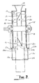
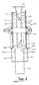
- the sample splitter 12 comprises a substantially cylindrical rotor chamber 17 having its central axis substantially horizontal.
- the upper portion of the rotor chamber 17 is formed with an opening accommodating a chute which provides the inlet 16 of the splitter.
- the lower face of the rotor chamber is formed with an opening which extends the length of the chamber and provides for the outlets 23a, 23b and 23c from the rotor chamber.
- the outlets are associated with a chute assembly 13 which provides three axially disposed chutes 13a, 13b and 13c whereby the two side chutes 13a and 13c are radially offset from the central chute 13b as may be observed from Figure 5.
- the rotor chamber accommodates a substantially cylindrical rotor 18 mounted for rotation about the central axis of the rotor chamber 17.
- the rotor is defined into three axially disposed annular zones A, B and C which are defined by means of two end plates 19 and two intermediate plates 20.
- the central zone B is divided into a plurality of radially disposed pockets by means of a set of equally spaced radial plates extending between the intermediate separator plates 20.
- One half of the pockets are defined by the radial plates and the intermediate separator plates 20 such that when the pockets are located below the inlet 16, material flowing into the splitter from the inlet 16 is deposited into the central zone B as shown at figure 3.
- An additional one quarter of the pockets in the central zone B are formed with first oblique diverter plates 21 which close off the entry into the pocket and cause material flowing into the central zone B from the inlet 16 of the splitter to be diverted into one end zone A of the rotor as shown at figure 2.
- the remaining one quarter of the pockets in the central zone B of the rotor are formed with second obliquely located diverter plates 22 which are opposed to the first oblique diverter plates 21 and close off the pocket of the central zone B of the rotor and divert material flowing into central zone B from the inlet 16 of the splitter into the other end zone C located at the other side of the central zone B as shown at figure 4.
- Each of the end zones A and C are formed with pockets by means of radial plates which may if desired by located at corresponding positions to the radial plates forming the pockets in the central zone B.
- the divisions 24a and 24b between the side chutes 13a and 13c and the central chute 13b are located such that they lie substantially centrally across side outlets 23a and 23c which are below the rotation paths of the end zones A and C of the rotor.
- the rotor 18 In operation, as material is delivered to the sample splitter 12 from the cyclone 11 through the inlet 16, the rotor 18 is caused to rotate. As each of the open central pockets of the central zone B pass underneath the inlet 16, material is collected in the pockets of the central zone B and on further rotation of the rotor, this material is deposited from the central outlet 23b. As each of the pockets of the one end zone A which communicate with the central zone B (see figure 2) pass beneath the inlet 16, material is collected in those pockets and on further rotation of the rotor, that material is deposited from the respective side outlet 23a and is further sub-divided into two flow paths of substantially equal cross-sectional area, by the division 24a between the central chute 13b and the respective side chute 13a.
- a sample splitter is produced which separates a quantity of material flowing into the splitter into two samples of approximately 121 ⁇ 2% of the total material and a further sample which comprises approximately 75% of the material. If desired the samples collected may be split further by dividing the flow paths further.
- the embodiment provides a sample splitter which by virtue of the rotor 18 provides an air lock valve to prevent any air escaping from the cyclone 11 and passing through the splitter to upset any of the sampling procedures. Particulate material moving under gravity within the splitter has minimal velocity and therefor has no opportunity to segregate according to particle size or density.
- the divisions 24a and 24b located below the two end zones A and C are shaped as shown at figure 5 such that their upper edge diverges away from the periphery of the rotor 18 with rotation of the rotor in order that any large particles which may be riding over the barriers do not become jammed between the barriers and the rotor.
- the unsplit material may be delivered to the rotor chamber through the end most zones A and C rather than the central zone.
- zones need not be sub-divided into pockets and there may be a somewhat direct communication between the inlet and outlet. In such a case the rotor would not serve as a valve or air lock.
- the scope of the present invention need not be limited to the particular scope of the embodiment described above.
- the invention may be used with any form of material which may be in a wet or dry form.
- the material may be introduced into the splitter by any suitable means and need not be introduced direct from its source.
- the relative volume of material delivered to each zone may vary as desired.
Landscapes
- Life Sciences & Earth Sciences (AREA)
- General Physics & Mathematics (AREA)
- Pathology (AREA)
- Health & Medical Sciences (AREA)
- Chemical & Material Sciences (AREA)
- Analytical Chemistry (AREA)
- Biochemistry (AREA)
- Physics & Mathematics (AREA)
- General Health & Medical Sciences (AREA)
- Immunology (AREA)
- Hydrology & Water Resources (AREA)
- Sampling And Sample Adjustment (AREA)
- Centrifugal Separators (AREA)
- Optical Communication System (AREA)
- Mechanical Treatment Of Semiconductor (AREA)
- Investigating, Analyzing Materials By Fluorescence Or Luminescence (AREA)
- Cyclones (AREA)
Claims (8)
- Probenteiler mit einer im wesentlichen zylindrischen Rotorkammer (17), deren zentrale Achse im wesentlichen horizontal verläuft und die wenigstens einen Einlaß (16) und wenigstens zwei Auslässe (23a und 23c) aufweist, und mit einem drehbar in der Rotorkammer (17) aufgenommenen und um eine im wesentlichen horizontale Achse rotierenden Rotor (18), dadurch gekennzichnet, daß der Rotor (18) in wenigstens zwei axial getrennte Zonen (A und C) unterteilt ist, daß jede der Zonen bei Drehung des Rotors periodisch mit dem Einlaß (16) in Verbindung tritt, daß jede Zone mit ihrem zugeordneten einzigen Ausgang in Verbindung steht und daß jeder Auslaß lediglich einer Zone zugeordnet ist.
- Probenteiler nach Anspruch 1, bei denen drei Auslässe (23a, 23b, 23c) und drei Zonen (A, B und C) vorhanden sind.
- Probenteiler nach Anspruch 2, in dem den Auslässen eine Rinneneinrichtung zugeordnet ist, der Flußweg von zwei Auslässen (23a und 23c) jeweils in zwei Flußwege unterteilt ist, von denen ein Flußweg jedes unterteilten Auslasses zu einer dem entsprechenden Auslaß zugeordneten Rinne (13a und 13c) führt und der andere Flußweg jedes unterteilten Auslasses zu einer gemeinsamen dritten Rinne (13b) Führt, und in dem der Flußweg vom verbleibenden nicht unterteilten Auslaß (23b) ebenfalls zu der dritten Rinne (13b) führt.
- Probenteiler noch Anspruch 1, 2 oder 3, in dem die Zonen (A. B und C) Seite an Seite zueinander angeordnet sind.
- Probenteiler nach den vorhergehenden Ansprüchen, in dem jede Zone in einen Satz von winkelmäßig um die Rotationsachse angeordneten Taschen unterteilt ist und in dem jede der Taschen ihrerseits bei Drehung das Rotors (17) mit dem Einlaß (16) in Verbindung tritt.
- Probenteiler nach den vorhergehenden Ansprüchen, in dem der Einlaß (16) oberhalb des Rotors (18) angeordnet ist.
- Probenteiler nach den vorhergehenden Ansprüchen, in dem die Auslässe unterhalb des Rotors (18) angeordnet sind.
- Probenteiler nach Anspruch 5, in dem die Sätze von Taschen jeder Zone abwechselnd mit dem Einlaß in Verbindung treten.
Applications Claiming Priority (2)
| Application Number | Priority Date | Filing Date | Title |
|---|---|---|---|
| AU8021/84 | 1984-11-07 | ||
| AUPG802184 | 1984-11-07 |
Publications (3)
| Publication Number | Publication Date |
|---|---|
| EP0200768A1 EP0200768A1 (de) | 1986-11-12 |
| EP0200768A4 EP0200768A4 (de) | 1988-07-14 |
| EP0200768B1 true EP0200768B1 (de) | 1991-05-15 |
Family
ID=3770832
Family Applications (1)
| Application Number | Title | Priority Date | Filing Date |
|---|---|---|---|
| EP85905593A Expired - Lifetime EP0200768B1 (de) | 1984-11-07 | 1985-11-01 | Probenteiler |
Country Status (8)
| Country | Link |
|---|---|
| EP (1) | EP0200768B1 (de) |
| JP (1) | JPS62500804A (de) |
| AU (1) | AU577425B2 (de) |
| BR (1) | BR8507288A (de) |
| CA (1) | CA1268352A (de) |
| DE (1) | DE3582883D1 (de) |
| WO (1) | WO1986003001A1 (de) |
| ZA (1) | ZA858467B (de) |
Families Citing this family (1)
| Publication number | Priority date | Publication date | Assignee | Title |
|---|---|---|---|---|
| GB201620735D0 (en) * | 2016-12-06 | 2017-01-18 | Advanced Laser Tech Ltd | Powder splitter |
Family Cites Families (8)
| Publication number | Priority date | Publication date | Assignee | Title |
|---|---|---|---|---|
| LU28413A1 (de) * | 1945-12-08 | |||
| US3186233A (en) * | 1963-09-09 | 1965-06-01 | Thiokol Chemical Corp | Continuous sampling device for dry ground materials |
| GB1310599A (en) * | 1970-11-24 | 1973-03-21 | Coal Industry Patents Ltd | Apparatus for dispensing and sampling fluid materials |
| GB1389124A (en) * | 1972-08-17 | 1975-04-03 | Kelly E | Sample taker to extract samples automatically and continuously |
| US3964513A (en) * | 1975-04-08 | 1976-06-22 | Hoffmann-La Roche Inc. | Rotating sampling valve |
| SU696337A1 (ru) * | 1977-06-02 | 1979-11-05 | Litovchenko Konstantin V | Устройство дл отбора и дозировани усредненной пробы сыпучего материала |
| FR2412838A1 (fr) * | 1977-12-20 | 1979-07-20 | Fives Cail Babcock | Appareil pour prelever des echantillons dans un courant de matieres granulaires ou pulverulentes |
| US4170900A (en) * | 1978-01-20 | 1979-10-16 | Ozawa Kenneth Y | Rotary sampler for particulate matter |
-
1985
- 1985-11-01 EP EP85905593A patent/EP0200768B1/de not_active Expired - Lifetime
- 1985-11-01 BR BR8507288A patent/BR8507288A/pt unknown
- 1985-11-01 WO PCT/AU1985/000268 patent/WO1986003001A1/en not_active Ceased
- 1985-11-01 AU AU50697/85A patent/AU577425B2/en not_active Ceased
- 1985-11-01 DE DE8585905593T patent/DE3582883D1/de not_active Expired - Fee Related
- 1985-11-01 JP JP60504989A patent/JPS62500804A/ja active Pending
- 1985-11-04 ZA ZA858467A patent/ZA858467B/xx unknown
- 1985-11-06 CA CA000494685A patent/CA1268352A/en not_active Expired - Lifetime
Also Published As
| Publication number | Publication date |
|---|---|
| JPS62500804A (ja) | 1987-04-02 |
| AU577425B2 (en) | 1988-09-22 |
| CA1268352A (en) | 1990-05-01 |
| DE3582883D1 (de) | 1991-06-20 |
| EP0200768A4 (de) | 1988-07-14 |
| ZA858467B (en) | 1986-07-30 |
| EP0200768A1 (de) | 1986-11-12 |
| BR8507288A (pt) | 1987-10-27 |
| WO1986003001A1 (en) | 1986-05-22 |
| AU5069785A (en) | 1986-06-03 |
Similar Documents
| Publication | Publication Date | Title |
|---|---|---|
| EP0068792B1 (de) | Multizyklonanlage für Fluide | |
| US3482771A (en) | Sludge centrifuge | |
| JPH0716629B2 (ja) | 遠心分離機 | |
| SU1024003A3 (ru) | Центробежный сепаратор | |
| KR890001390B1 (ko) | 입상물질 분리기 | |
| WO1983001584A1 (en) | Improvements in or relating to cyclone separators | |
| US3858794A (en) | Sludge centrifuge | |
| EP0210729B1 (de) | Sichter zum Sortieren von Materialpartikeln | |
| US4817442A (en) | Sample splitter | |
| JPS586256A (ja) | 遠心分離機 | |
| US2698142A (en) | Bowl mill with novel bowl and air flow directing means | |
| AU577425B2 (en) | Sample splitter | |
| US3084798A (en) | Cyclone | |
| US4193537A (en) | Centrifugal separator with presedimentation means | |
| US4083500A (en) | Tube mill | |
| NZ522739A (en) | Centrifuge with a sieve system and method for operating the same | |
| CA1076781A (en) | Apparatus for processing dust-carrying gas and bulk goods | |
| CA1115649A (en) | Apparatus for separating or concentrating gaseous mixtures | |
| US4511462A (en) | Method and apparatus for sorting particulate material | |
| FR2434652A1 (fr) | Separateur cyclone muni de moyens d'alimentation en air d'acceleration | |
| WO1988003189A1 (en) | Refiner | |
| US2989146A (en) | Separating apparatus | |
| RU2136397C1 (ru) | Аэрогравитационный разделитель сыпучих материалов | |
| WO1993011877A1 (en) | Centrifugal separator | |
| US3036759A (en) | Centrifugal bowl for separating sludge-containing liquids |
Legal Events
| Date | Code | Title | Description |
|---|---|---|---|
| PUAI | Public reference made under article 153(3) epc to a published international application that has entered the european phase |
Free format text: ORIGINAL CODE: 0009012 |
|
| AK | Designated contracting states |
Kind code of ref document: A1 Designated state(s): AT BE CH DE FR GB IT LI LU NL SE |
|
| 17P | Request for examination filed |
Effective date: 19870507 |
|
| RBV | Designated contracting states (corrected) |
Designated state(s): BE DE FR GB SE |
|
| R17P | Request for examination filed (corrected) |
Effective date: 19870507 |
|
| A4 | Supplementary search report drawn up and despatched |
Effective date: 19880714 |
|
| 17Q | First examination report despatched |
Effective date: 19891026 |
|
| GRAA | (expected) grant |
Free format text: ORIGINAL CODE: 0009210 |
|
| AK | Designated contracting states |
Kind code of ref document: B1 Designated state(s): BE DE FR GB SE |
|
| PG25 | Lapsed in a contracting state [announced via postgrant information from national office to epo] |
Ref country code: SE Effective date: 19910515 Ref country code: BE Effective date: 19910515 |
|
| REF | Corresponds to: |
Ref document number: 3582883 Country of ref document: DE Date of ref document: 19910620 |
|
| EN | Fr: translation not filed | ||
| PG25 | Lapsed in a contracting state [announced via postgrant information from national office to epo] |
Ref country code: FR Effective date: 19911004 |
|
| PLBE | No opposition filed within time limit |
Free format text: ORIGINAL CODE: 0009261 |
|
| STAA | Information on the status of an ep patent application or granted ep patent |
Free format text: STATUS: NO OPPOSITION FILED WITHIN TIME LIMIT |
|
| 26N | No opposition filed | ||
| REG | Reference to a national code |
Ref country code: FR Ref legal event code: ST |
|
| PGFP | Annual fee paid to national office [announced via postgrant information from national office to epo] |
Ref country code: GB Payment date: 19921023 Year of fee payment: 8 |
|
| PGFP | Annual fee paid to national office [announced via postgrant information from national office to epo] |
Ref country code: DE Payment date: 19921120 Year of fee payment: 8 |
|
| PG25 | Lapsed in a contracting state [announced via postgrant information from national office to epo] |
Ref country code: GB Effective date: 19931101 |
|
| GBPC | Gb: european patent ceased through non-payment of renewal fee |
Effective date: 19931101 |
|
| PG25 | Lapsed in a contracting state [announced via postgrant information from national office to epo] |
Ref country code: DE Effective date: 19940802 |