EP0200788A1 - Procede de retour d'un arbre rotatif a un point de reference - Google Patents
Procede de retour d'un arbre rotatif a un point de reference Download PDFInfo
- Publication number
- EP0200788A1 EP0200788A1 EP85905233A EP85905233A EP0200788A1 EP 0200788 A1 EP0200788 A1 EP 0200788A1 EP 85905233 A EP85905233 A EP 85905233A EP 85905233 A EP85905233 A EP 85905233A EP 0200788 A1 EP0200788 A1 EP 0200788A1
- Authority
- EP
- European Patent Office
- Prior art keywords
- reference point
- coordinate system
- rotary axis
- machine
- workpiece coordinate
- Prior art date
- Legal status (The legal status is an assumption and is not a legal conclusion. Google has not performed a legal analysis and makes no representation as to the accuracy of the status listed.)
- Granted
Links
Images

Classifications
-
- G—PHYSICS
- G05—CONTROLLING; REGULATING
- G05B—CONTROL OR REGULATING SYSTEMS IN GENERAL; FUNCTIONAL ELEMENTS OF SUCH SYSTEMS; MONITORING OR TESTING ARRANGEMENTS FOR SUCH SYSTEMS OR ELEMENTS
- G05B19/00—Program-control systems
- G05B19/02—Program-control systems electric
- G05B19/18—Numerical control [NC], i.e. automatically operating machines, in particular machine tools, e.g. in a manufacturing environment, so as to execute positioning, movement or co-ordinated operations by means of program data in numerical form
- G05B19/401—Numerical control [NC], i.e. automatically operating machines, in particular machine tools, e.g. in a manufacturing environment, so as to execute positioning, movement or co-ordinated operations by means of program data in numerical form characterised by control arrangements for measuring, e.g. calibration and initialisation, measuring workpiece for machining purposes
- G05B19/4015—Numerical control [NC], i.e. automatically operating machines, in particular machine tools, e.g. in a manufacturing environment, so as to execute positioning, movement or co-ordinated operations by means of program data in numerical form characterised by control arrangements for measuring, e.g. calibration and initialisation, measuring workpiece for machining purposes going to a reference at the beginning of machine cycle, e.g. for calibration
Definitions
- This invention relates to a method of restoring a rotary axis to a reference point. More particularly, the invention relates to a rotary axis reference point restoration method for rotating the rotary table of a machine to position the table at a predetermined angular position.
- a rotary axis is rotated to position the table at a predetermined angular position by numerical control in the same manner that control is performed along linear axes (e.g. X, Y and Z axes) so that a workpiece placed upon the table may be subjected to boring and other machining.
- linear axes e.g. X, Y and Z axes
- a rotational direction workpiece coordinate system serving as a programming reference for a rotational direction machine coordinate system is decided
- data specifying an angle r between the origin of the workpiece coordinate system and a reference point in the machine coordinate system are commanded by a program (a G-function instruction for setting a coordinate system)
- the position of the rotary axis is controlled by NC program data created on the basis of the workpiece coordinate system, and present positions Pm, Pw in the machine and workpiece coordinate systems, respectively, are monitored.
- NC program data are created including at least NC data specifying an angle r between an origin of the workpiece coordinate system and a reference point in the machine coordinate system, and rotational direction positioning data based on the workpiece coordinate system, and a rotary axis is positionally controlled based on the NC program data.
- the method of the invention includes updating present positions Pm, Pw of a fixed point Q on the rotary axis in the machine coordinate system and workpiece coordinate system in dependence upon rotation of the rotary axis, obtaining an angle a that satisfies the equations in response to a reference point restoration command, then rotating the rotary axis by
- Fig. 1 is a view for describing the general features of the present invention.
- MR represents a rotating direction reference point (hereafter referred to simply as a "reference point") in a machine coordinate system
- WR denotes a rotating direction origin of a workpiece coordinate system.
- the angle between the reference point MR and the origin WR of the workpiece coordinate system is r.
- the fixed point Q is situated at the reference point MR and the fixed point Q' is situated at the origin WR of the workpiece coordinate system when the rotary axis has been restored to the reference point, as shown in Fig. 1(A). If the rotary axis 11 is rotated by (360 n+a)° from this state, the positional relationship among the fixed points Q, Q', reference point MR and the origin WR of the workpiece coordinate system will be as illustrated in Fig. l(B). The present position P m in the machine coordinate system becomes and the position Pw in the workpiece coordinate system becomes
- F ig. 2 is a block diagram of a numerical control unit to which the present invention can be applied
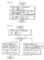
- Fig. 3 is a flowchart of processing according to the invention.
- numeral 101 denotes a processor, 102 a ROM storing a control program, 103 a RAM, 104 a working memory, 105 an NC tape, 106 an input unit for reading NC program data from the NC tape 105 and for inputting the data, 107 a pulse distributor, 108 a servo circuit, 109 a motor for driving the rotary axis , 110 an operator's panel, and 111 a bus line.
- the NC data are read from the NC tape 105 and stored in the RAM 103. If the system is now started by pressing a start button on the operator's panel 110, the processor 101 reads NC data out of the RAM 103 one block at a time and executes predetermined numerical control processing.
- the processor 101 stores an angle specified by the instruction in the working memory 104 as the present position Pw in the workpiece coordinate system. If a positioning command is issued, positioning processing, described below, is executed. Note that the description will deal with a case where the rotary axis is subjected to simultaneous one-axis control.
- the processor obtains a rotary axis incremental value Ri and performs an operation in accordance with the expression (where F is the rotational velocity and ⁇ T is a predetermined period of time) to calculate an amount of movement ⁇ A to be traversed in the time ⁇ T.
- ⁇ A is applied to the pulse distributor 107 at intervals of ⁇ T, and the pulse distributor 107 generates distributed pulses P A applied to the servo circuit 108, thereby rotating the motor 109 to rotate the rotary axis 11 shown in Fig. 1.
- the processor updates the present position and a remaining amount of rotation Ar at intervals of ⁇ T.
- the present position Pm in the machine coordinate system and the present position Pw in the workpiece coordinate system, both of which are stored in the working memory 104 are updated every T in accordance with the expressions
- the remaining amount of rotation AR which has been stored in the working memory 104, is updated in accordance with the expression
- the processor 101 subsequently executes origin restoration processing in accordance with the flowchart shown in Fig. 3. It should be noted that the reference point restoration is assumed to be performed within 360 of rotation.
- processing is executed in accordance with the flowchart shown in Fig. 4. Specifically, the following steps are executed if a reference point restoration command is generated when the rotary axis is in the state shown in Fig. l(B):
- the rotary axis is rotated by (360 -
- the values of Pm, Pw are updated to the values indicated by the Eqs. (7), (8) by (360 -
- the arrangement is such that a reference point restoration is executed by a first step of updating the present positions Pm, Pw in the machine and workpiece coordinate systems, respectively, in dependence upon rotation of the rotary axis and, in response to a reference point restortion command, obtaining the angle a that satisfies the equations a second step of rotating the rotary axis by a° to return the rotary axis to the reference point in the machine coordinate system, and a third step of updating the present positions Pm, Pw in the machine and workpiece coordinate systems, respectively, in accordance with, e.g. the following expressions:
- the reference point restoration can be performed by rotation through less than 360°, namely in a short period of time, and the workpiece coordinate system can be returned to its original state after the reference point restoration. This dispenses with the need to set the workpiece coordinate system after the restoration is completed, as is necessary in the prior art.
- the arrangement is such that a reference point restoration is executed by a first step of updating the present positions Pm, Pw in the machine and workpiece coordinate systems, respectively, in dependence upon rotation of the rotary axis and, in response to a reference point restortion command, obtaining the angle a that satisfies the equations a second step of comparing
Landscapes
- Engineering & Computer Science (AREA)
- Human Computer Interaction (AREA)
- Manufacturing & Machinery (AREA)
- Physics & Mathematics (AREA)
- General Physics & Mathematics (AREA)
- Automation & Control Theory (AREA)
- Numerical Control (AREA)
- Control Of Position Or Direction (AREA)
Abstract
Applications Claiming Priority (2)
| Application Number | Priority Date | Filing Date | Title |
|---|---|---|---|
| JP59220844A JPS61100815A (ja) | 1984-10-20 | 1984-10-20 | 回転軸のリフアレンス点復帰方法 |
| JP220844/84 | 1984-10-20 |
Publications (3)
| Publication Number | Publication Date |
|---|---|
| EP0200788A1 true EP0200788A1 (fr) | 1986-11-12 |
| EP0200788A4 EP0200788A4 (fr) | 1988-12-12 |
| EP0200788B1 EP0200788B1 (fr) | 1992-03-11 |
Family
ID=16757427
Family Applications (1)
| Application Number | Title | Priority Date | Filing Date |
|---|---|---|---|
| EP85905233A Expired EP0200788B1 (fr) | 1984-10-20 | 1985-10-18 | Procede de retour d'un arbre rotatif a un point de reference |
Country Status (5)
| Country | Link |
|---|---|
| US (1) | US4783617A (fr) |
| EP (1) | EP0200788B1 (fr) |
| JP (1) | JPS61100815A (fr) |
| DE (1) | DE3585620D1 (fr) |
| WO (1) | WO1986002470A1 (fr) |
Cited By (2)
| Publication number | Priority date | Publication date | Assignee | Title |
|---|---|---|---|---|
| EP0416258A1 (fr) * | 1989-07-21 | 1991-03-13 | Toyoda Koki Kabushiki Kaisha | Méthode pour détecter les coordonnées de position du point à meuler d'une machine à meuler et équipement rattaché |
| EP0372082A4 (en) * | 1988-02-24 | 1991-07-03 | Fanuc Ltd | Method for returning to origin |
Families Citing this family (5)
| Publication number | Priority date | Publication date | Assignee | Title |
|---|---|---|---|---|
| JP3071758B2 (ja) * | 1998-05-20 | 2000-07-31 | ヤマザキマザック株式会社 | 3次元レーザ加工機及び3次元レーザ加工機における加工プログラムの作成制御方法 |
| ITMI981230A1 (it) * | 1998-06-03 | 1999-12-03 | Matec Spa | Motore passo-passo dotato di dispositivo di azzeramento a precisione elevata |
| DE10108139A1 (de) * | 2001-02-20 | 2002-08-29 | Boegl Max Bauunternehmung Gmbh | Verfahren zur Vermessung und/oder Bearbeitung eines Werkstücks |
| CN100573054C (zh) * | 2008-02-01 | 2009-12-23 | 三一重工股份有限公司 | 一种工程车辆转台的回转角度检测装置及其工程车辆 |
| CN117283009B (zh) * | 2023-11-14 | 2025-11-18 | 中国航发沈阳黎明航空发动机有限责任公司 | 一种提高线性焊整体叶盘孔加工位置精度的方法 |
Family Cites Families (8)
| Publication number | Priority date | Publication date | Assignee | Title |
|---|---|---|---|---|
| US3546442A (en) * | 1967-07-03 | 1970-12-08 | Northern Electric Co | Digital subtractor with means for providing conjugate angle |
| JPS50119181A (fr) * | 1974-03-08 | 1975-09-18 | ||
| JPS5926401Y2 (ja) * | 1974-04-26 | 1984-08-01 | 豊田工機株式会社 | 移動体の原点復帰装置 |
| JPS5160410A (ja) * | 1974-11-25 | 1976-05-26 | Hitachi Ltd | Kotonaruichinisonzaisurufukusuno zahyono gentenitsuchiho |
| JPS51116484A (en) * | 1975-04-03 | 1976-10-13 | Okuma Mach Works Ltd | Position control device for circular table |
| JPS5611515A (en) * | 1979-07-10 | 1981-02-04 | Chiyou Lsi Gijutsu Kenkyu Kumiai | Aligning unit |
| JPS57189207A (en) * | 1981-05-18 | 1982-11-20 | Fanuc Ltd | Numerical control system |
| JPS5968003A (ja) * | 1982-10-13 | 1984-04-17 | Toyoda Mach Works Ltd | 数値制御工作機械の非常機械原点復帰装置 |
-
1984
- 1984-10-20 JP JP59220844A patent/JPS61100815A/ja active Pending
-
1985
- 1985-10-18 EP EP85905233A patent/EP0200788B1/fr not_active Expired
- 1985-10-18 WO PCT/JP1985/000586 patent/WO1986002470A1/fr not_active Ceased
- 1985-10-18 DE DE8585905233T patent/DE3585620D1/de not_active Expired - Lifetime
- 1985-10-18 US US06/881,023 patent/US4783617A/en not_active Expired - Fee Related
Cited By (3)
| Publication number | Priority date | Publication date | Assignee | Title |
|---|---|---|---|---|
| EP0372082A4 (en) * | 1988-02-24 | 1991-07-03 | Fanuc Ltd | Method for returning to origin |
| EP0416258A1 (fr) * | 1989-07-21 | 1991-03-13 | Toyoda Koki Kabushiki Kaisha | Méthode pour détecter les coordonnées de position du point à meuler d'une machine à meuler et équipement rattaché |
| US5224050A (en) * | 1989-07-21 | 1993-06-29 | Toyoda Koki Kabushiki Kaisha | Method for detecting the coordinate position of the grinding point of a grinding wheel and related device |
Also Published As
| Publication number | Publication date |
|---|---|
| JPS61100815A (ja) | 1986-05-19 |
| DE3585620D1 (de) | 1992-04-16 |
| WO1986002470A1 (fr) | 1986-04-24 |
| EP0200788B1 (fr) | 1992-03-11 |
| EP0200788A4 (fr) | 1988-12-12 |
| US4783617A (en) | 1988-11-08 |
Similar Documents
| Publication | Publication Date | Title |
|---|---|---|
| EP0046032B1 (fr) | Méthode de commande numérique | |
| EP1302829B1 (fr) | Commande numérique | |
| US4659971A (en) | Robot controlling system | |
| EP1353251B1 (fr) | Commande numérique | |
| US4722063A (en) | Method of calculating actual arm lengths and compensating for angular errors | |
| US5075865A (en) | Method and apparatus for involute interpolation | |
| EP0077177A1 (fr) | Méthode et dispositif pour la commande numérique | |
| US5004968A (en) | Method for acceleration and deceleration control of servomotors | |
| US5646493A (en) | Robot profile control method | |
| US5545959A (en) | Speed control method for a numerical control apparatus | |
| EP0200788B1 (fr) | Procede de retour d'un arbre rotatif a un point de reference | |
| US4862381A (en) | Position control method in which a cartesian point is transformed through two cartesian coordinate systems | |
| US5578913A (en) | NC device controlling machining processes with pre- and post-execution in-position values | |
| EP0161321B1 (fr) | Procede d'usinage pour machine-outil | |
| US20040207356A1 (en) | Numerical controller | |
| US5347461A (en) | Tool travel path creating method | |
| US5155424A (en) | Numerical control method | |
| EP0362391A1 (fr) | Procede d'interpolation de developpante | |
| US4495561A (en) | Numerical control method | |
| JPH0630011B2 (ja) | 数値制御加工再開制御方式 | |
| EP0509102A1 (fr) | Procede de simulation d'un travail d'usinage | |
| US5773950A (en) | Program creating method for uniform-shape machining | |
| JPH0778031A (ja) | サーボモータの制御方法 | |
| EP0362393A1 (fr) | Systeme d'interpolation d'impulsions de grande precision | |
| JP3232252B2 (ja) | 位置決め制御装置及び位置決め制御方法 |
Legal Events
| Date | Code | Title | Description |
|---|---|---|---|
| PUAI | Public reference made under article 153(3) epc to a published international application that has entered the european phase |
Free format text: ORIGINAL CODE: 0009012 |
|
| 17P | Request for examination filed |
Effective date: 19860703 |
|
| AK | Designated contracting states |
Kind code of ref document: A1 Designated state(s): DE FR GB |
|
| A4 | Supplementary search report drawn up and despatched |
Effective date: 19881212 |
|
| 17Q | First examination report despatched |
Effective date: 19900918 |
|
| GRAA | (expected) grant |
Free format text: ORIGINAL CODE: 0009210 |
|
| AK | Designated contracting states |
Kind code of ref document: B1 Designated state(s): DE FR GB |
|
| REF | Corresponds to: |
Ref document number: 3585620 Country of ref document: DE Date of ref document: 19920416 |
|
| ET | Fr: translation filed | ||
| PLBI | Opposition filed |
Free format text: ORIGINAL CODE: 0009260 |
|
| 26 | Opposition filed |
Opponent name: ROBERT BOSCH GMBH Effective date: 19921209 |
|
| PGFP | Annual fee paid to national office [announced via postgrant information from national office to epo] |
Ref country code: GB Payment date: 19941010 Year of fee payment: 10 Ref country code: DE Payment date: 19941010 Year of fee payment: 10 |
|
| PGFP | Annual fee paid to national office [announced via postgrant information from national office to epo] |
Ref country code: FR Payment date: 19941011 Year of fee payment: 10 |
|
| RDAG | Patent revoked |
Free format text: ORIGINAL CODE: 0009271 |
|
| STAA | Information on the status of an ep patent application or granted ep patent |
Free format text: STATUS: PATENT REVOKED |
|
| 27W | Patent revoked |
Effective date: 19950109 |
|
| GBPR | Gb: patent revoked under art. 102 of the ep convention designating the uk as contracting state |
Free format text: 950109 |