EP0200809A2 - Filtre à huile avec un échangeur de chaleur intégré - Google Patents
Filtre à huile avec un échangeur de chaleur intégré Download PDFInfo
- Publication number
- EP0200809A2 EP0200809A2 EP85106783A EP85106783A EP0200809A2 EP 0200809 A2 EP0200809 A2 EP 0200809A2 EP 85106783 A EP85106783 A EP 85106783A EP 85106783 A EP85106783 A EP 85106783A EP 0200809 A2 EP0200809 A2 EP 0200809A2
- Authority
- EP
- European Patent Office
- Prior art keywords
- oil
- base
- coolant
- channels
- channel
- Prior art date
- Legal status (The legal status is an assumption and is not a legal conclusion. Google has not performed a legal analysis and makes no representation as to the accuracy of the status listed.)
- Withdrawn
Links
Images
Classifications
-
- B—PERFORMING OPERATIONS; TRANSPORTING
- B01—PHYSICAL OR CHEMICAL PROCESSES OR APPARATUS IN GENERAL
- B01D—SEPARATION
- B01D35/00—Filtering devices having features not specifically covered by groups B01D24/00 - B01D33/00, or for applications not specifically covered by groups B01D24/00 - B01D33/00; Auxiliary devices for filtration; Filter housing constructions
- B01D35/18—Heating or cooling the filters
-
- F—MECHANICAL ENGINEERING; LIGHTING; HEATING; WEAPONS; BLASTING
- F01—MACHINES OR ENGINES IN GENERAL; ENGINE PLANTS IN GENERAL; STEAM ENGINES
- F01M—LUBRICATING OF MACHINES OR ENGINES IN GENERAL; LUBRICATING INTERNAL COMBUSTION ENGINES; CRANKCASE VENTILATING
- F01M1/00—Pressure lubrication
- F01M1/10—Lubricating systems characterised by the provision therein of lubricant venting or purifying means, e.g. of filters
-
- F—MECHANICAL ENGINEERING; LIGHTING; HEATING; WEAPONS; BLASTING
- F01—MACHINES OR ENGINES IN GENERAL; ENGINE PLANTS IN GENERAL; STEAM ENGINES
- F01M—LUBRICATING OF MACHINES OR ENGINES IN GENERAL; LUBRICATING INTERNAL COMBUSTION ENGINES; CRANKCASE VENTILATING
- F01M5/00—Heating, cooling, or controlling temperature of lubricant; Lubrication means facilitating engine starting
- F01M5/002—Cooling
-
- F—MECHANICAL ENGINEERING; LIGHTING; HEATING; WEAPONS; BLASTING
- F28—HEAT EXCHANGE IN GENERAL
- F28D—HEAT-EXCHANGE APPARATUS, NOT PROVIDED FOR IN ANOTHER SUBCLASS, IN WHICH THE HEAT-EXCHANGE MEDIA DO NOT COME INTO DIRECT CONTACT
- F28D7/00—Heat-exchange apparatus having stationary tubular conduit assemblies for both heat-exchange media, the media being in contact with different sides of a conduit wall
- F28D7/10—Heat-exchange apparatus having stationary tubular conduit assemblies for both heat-exchange media, the media being in contact with different sides of a conduit wall the conduits being arranged one within the other, e.g. concentrically
- F28D7/103—Heat-exchange apparatus having stationary tubular conduit assemblies for both heat-exchange media, the media being in contact with different sides of a conduit wall the conduits being arranged one within the other, e.g. concentrically consisting of more than two coaxial conduits or modules of more than two coaxial conduits
-
- F—MECHANICAL ENGINEERING; LIGHTING; HEATING; WEAPONS; BLASTING
- F28—HEAT EXCHANGE IN GENERAL
- F28D—HEAT-EXCHANGE APPARATUS, NOT PROVIDED FOR IN ANOTHER SUBCLASS, IN WHICH THE HEAT-EXCHANGE MEDIA DO NOT COME INTO DIRECT CONTACT
- F28D9/00—Heat-exchange apparatus having stationary plate-like or laminated conduit assemblies for both heat-exchange media, the media being in contact with different sides of a conduit wall
- F28D9/0012—Heat-exchange apparatus having stationary plate-like or laminated conduit assemblies for both heat-exchange media, the media being in contact with different sides of a conduit wall the apparatus having an annular form
-
- F—MECHANICAL ENGINEERING; LIGHTING; HEATING; WEAPONS; BLASTING
- F01—MACHINES OR ENGINES IN GENERAL; ENGINE PLANTS IN GENERAL; STEAM ENGINES
- F01M—LUBRICATING OF MACHINES OR ENGINES IN GENERAL; LUBRICATING INTERNAL COMBUSTION ENGINES; CRANKCASE VENTILATING
- F01M11/00—Component parts, details or accessories, not provided for in, or of interest apart from, groups F01M1/00 - F01M9/00
- F01M11/03—Mounting or connecting of lubricant purifying means relative to the machine or engine; Details of lubricant purifying means
-
- F—MECHANICAL ENGINEERING; LIGHTING; HEATING; WEAPONS; BLASTING
- F01—MACHINES OR ENGINES IN GENERAL; ENGINE PLANTS IN GENERAL; STEAM ENGINES
- F01M—LUBRICATING OF MACHINES OR ENGINES IN GENERAL; LUBRICATING INTERNAL COMBUSTION ENGINES; CRANKCASE VENTILATING
- F01M1/00—Pressure lubrication
- F01M1/10—Lubricating systems characterised by the provision therein of lubricant venting or purifying means, e.g. of filters
- F01M2001/1007—Lubricating systems characterised by the provision therein of lubricant venting or purifying means, e.g. of filters characterised by the purification means combined with other functions
- F01M2001/1014—Lubricating systems characterised by the provision therein of lubricant venting or purifying means, e.g. of filters characterised by the purification means combined with other functions comprising supply of additives
-
- F—MECHANICAL ENGINEERING; LIGHTING; HEATING; WEAPONS; BLASTING
- F01—MACHINES OR ENGINES IN GENERAL; ENGINE PLANTS IN GENERAL; STEAM ENGINES
- F01M—LUBRICATING OF MACHINES OR ENGINES IN GENERAL; LUBRICATING INTERNAL COMBUSTION ENGINES; CRANKCASE VENTILATING
- F01M1/00—Pressure lubrication
- F01M1/10—Lubricating systems characterised by the provision therein of lubricant venting or purifying means, e.g. of filters
- F01M2001/105—Lubricating systems characterised by the provision therein of lubricant venting or purifying means, e.g. of filters characterised by the layout of the purification arrangements
- F01M2001/1092—Lubricating systems characterised by the provision therein of lubricant venting or purifying means, e.g. of filters characterised by the layout of the purification arrangements comprising valves bypassing the filter
-
- F—MECHANICAL ENGINEERING; LIGHTING; HEATING; WEAPONS; BLASTING
- F01—MACHINES OR ENGINES IN GENERAL; ENGINE PLANTS IN GENERAL; STEAM ENGINES
- F01M—LUBRICATING OF MACHINES OR ENGINES IN GENERAL; LUBRICATING INTERNAL COMBUSTION ENGINES; CRANKCASE VENTILATING
- F01M11/00—Component parts, details or accessories, not provided for in, or of interest apart from, groups F01M1/00 - F01M9/00
- F01M11/03—Mounting or connecting of lubricant purifying means relative to the machine or engine; Details of lubricant purifying means
- F01M2011/031—Mounting or connecting of lubricant purifying means relative to the machine or engine; Details of lubricant purifying means characterised by mounting means
- F01M2011/033—Mounting or connecting of lubricant purifying means relative to the machine or engine; Details of lubricant purifying means characterised by mounting means comprising coolers or heat exchangers
-
- F—MECHANICAL ENGINEERING; LIGHTING; HEATING; WEAPONS; BLASTING
- F28—HEAT EXCHANGE IN GENERAL
- F28F—DETAILS OF HEAT-EXCHANGE AND HEAT-TRANSFER APPARATUS, OF GENERAL APPLICATION
- F28F2250/00—Arrangements for modifying the flow of the heat exchange media, e.g. flow guiding means; Particular flow patterns
- F28F2250/10—Particular pattern of flow of the heat exchange media
- F28F2250/102—Particular pattern of flow of the heat exchange media with change of flow direction
Definitions
- the invention relates to an oil filter with an integrated heat exchanger, in particular for motor vehicle engines, consisting of a filter insert and a filter housing which receives the insert and has a base connected to the engine, and the oil on the underside of the base flows into the base on the underside of the engine and after Flows through inlet channels in the base and the filter insert through a central outlet channel that passes through the base in the longitudinal direction and flows to the engine.
- a filter with an integrated heat exchanger is known.
- the heat exchange takes place in the filter housing completely surrounding the filter insert.
- an additional, external annular space is provided in the housing, through which a cooling medium flows essentially in cross flow to the medium to be filtered and cooled or heated.
- the integration of the heat exchanger in the already existing base of the filter housing ideally solves the requirement for minimizing the size, while the high efficiency of the heat exchanger is achieved by guiding the two media in counterflow.
- the concentric arrangement of the channels ensures optimal use of space that does not contain any dead space.
- the circular flow of coolant is achieved by having coolant inlet and outlet close lie adjacent to this or beyond a radially extending partition, so that the coolant flowing through describes an approximate 360 ° arc. This results in a clearly defined, uniform flow direction of the cooling medium in the heat exchanger.
- the closely adjacent position of the coolant inlet and outlet allows space-saving, parallel routing of the associated lines or hoses.
- the cross-sectional shape of the coolant channel is preferably that of a high, narrow rectangle, since a relatively large wall area is thus achieved with a small radial space requirement.
- the arrangement of chamber-like channels described is provided.
- the chamber cross-sectional shape is similar to that of the coolant channel, but is only about half its height.
- the circular extent of the chambers is such that it clearly exceeds the height of the chambers.
- an arrangement can comprise at least two chambers per level, but it can also be a larger number.
- a plurality of chamber arrangements and coolant channels can also be present in the radial direction.
- a good heat transfer also contributes to the fact that the walls are largely covered by oil on one side and the coolant on the other. The There are no interfaces or gaps that prevent heat transfer.
- a preferred embodiment of the oil filter provides that the base has three concentric, parallel flow channels for the coolant and between these two concentric chamber arrangements for the oil. On the one hand, this achieves a sufficiently large heat exchange area, but on the other hand, a sufficiently large duct cross section is still ensured, in which pressure losses of oil and coolant do not become too high.
- ribs or projections are provided on the walls of the channels and chambers, preferably on the heat-exchanging walls. The ribs sensibly extend perpendicular to the Flow direction, ie parallel to the central drainage channel, in order to ensure the best possible swirl. At the same time, the heat exchange area is further increased.
- the ribs are arranged alternately on opposite walls of a channel and have a height that extends approximately to the middle of the channel.
- a meandering flow of the media and thus an extended flow path are achieved with the result of an improved heat exchange.
- the base consists of two nested parts that are sealed against one another, namely a cup part with the central drainage channel and an insert part.
- the insert part comprises at least one annular chamber arrangement, but can also have two or more such arrangements.
- the two parts can be sealed off from one another, for example by O-rings or by gluing.
- the nested parts are covered or closed at the top by the housing receiving the filter insert. Due to the described construction of the base in two parts, the assembly effort during manufacture is very low.
- aluminum has both good thermal conductivity and low weight and is very easy to machine.
- the oil filter according to the invention with an integrated heat exchanger is therefore both more efficient and less expensive to produce and more effective than known oil filters of this type.
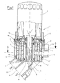
- the oil filter 1 consists of a filter housing 3 which receives a filter insert 2 and which is arranged on a filter base 4.
- the housing 3 surrounds the filter insert 2 only in its lower part, since in the exemplary embodiment a disposable Filter cartridge is inserted.
- the filter base 4 consists of two parts 4 'and 4 ", namely a cup part 4' (hatching increasing to the right) and an insert part 4" (hatching increasing to the left).
- the cup part 4 ' has a central drain channel 5 which runs in the direction of the longitudinal axis of the oil filter 1. This opens into the lower part of the base 4 in a line 14 which leads to a motor (not shown). Parallel to this is a second line 13 coming from the engine. Both lines 13 and 14 are used to guide engine oil.
- the insert part 4 is inserted against the cup part 4' by means of seals 18.
- the insert part 4" has four walls 9 parallel to one another and to the central drainage channel 5 in the example of the invention shown, thereby interacting with the cup part 4 'channels 6 and 7 are formed, the cross-sectional shape of which corresponds to that of a tall, narrow rectangle.
- the channels 7 are used to guide the oil that gets there through inlets 11 on the underside of the channels 7.
- the connection of the channels 7 to the filter housing 3 or the filter insert 2 located therein produce outlets 12 at the upper ends of the channels 7.
- the channels 6, which alternate with the channels 7 when viewed in the radial direction, serve to guide a coolant which is expediently cooling water from the engine cooling water circuit.
- the coolant channels 6 are closed by the underside of the filter housing 3, so that there are two completely separate circuits in which mixing of oil and coolant is excluded.
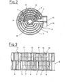
- FIG. 2 shows a section along the line AA in FIG.
- the central drainage channel 5 In the middle, the central drainage channel 5 can be seen, which has on its inside surface-enlarging ribs 10 'which run in the direction of the oil flow.
- the coolant passes through an inlet connector 15 on the outside of the base 3 into the channels 6, which are arranged concentrically with the outlet channel 5 at different distances.
- the channels 6 describe a reasonable 0 360 approaching bend and terminating at an outlet 16 for discharging the coolant, wherein the separation is effected from the inlet by a partition 17th
- two channels 7 are arranged for guiding the oil, these being divided into sections extending from one inlet 8 to the next inlet 8.
- the design of the channels 7 is particularly clear from the rolled-up representation of a part of a wall 9 of a channel 7 shown in FIG. 3.
- the channel 7 is divided into chamber-like channels 7 'and 7 ", arranged in two superimposed levels, the length of the Channels or chambers 7 'and 7 "is greater than their height.
- At one of the lower corners of the lower chambers 7 ' there is an inlet 11 through which oil flows into the chamber 7'.
- a passage 8 which in turn lies at the beginning of a chamber 7 "of the upper level.
- the upper chamber 7" in turn has an outlet 12 diagonally opposite the passage 8.
- ribs 10 on the walls 9 the heat exchanger area is increased and turbulence is generated in the flowing media.
- the height, number and spacing of the ribs 10 are at the discretion of the person skilled in the art and judge according to the requirements regarding heat exchange and pressure loss.
- An embodiment of the base without ribs or with ribs only in part of the channels is also conceivable.
- the engine oil to be filtered passes through line 13 coming from the engine into the base 4 of the oil filter. From there it is distributed through the inlets 11 into the chamber-like channels or chambers 7 '. After flowing through the chambers 7 'of the lower level in a circular direction, in the example clockwise, the transition into the chambers 7 "of the upper level follows through the passages 8. The chambers 7" are also flowed through by the oil in a circular direction in a clockwise direction and leave through outlets 12. Furthermore, the oil flows through the filter housing 3 and the filter insert 2 into the central drain channel 5 and from there through the line 14 back to the engine.
- coolant flows through the inlet port, i. a. Cooling water in the channels 6, this flows in a circular direction opposite to the oil, that is counterclockwise and exits through the outlet port 16 and is z. B. returned to the engine's cooling water circuit.
- a heat exchange takes place through the common walls 9 of the channels 6 and chambers 7 'and 7 ", the effectiveness of which is very high due to the fact that the media flowing past one another - coolant and oil - flow in countercurrent.
- the main purpose of the heat exchanger is to cool the with high temperature oil coming from the engine, but is also in the cold start phase the reverse effect is advantageous because the cooling water heats up faster than the engine oil.
- the already heated cooling water gives off heat to the oil, which improves its flow and lubricity in a desirable manner.
Landscapes
- Engineering & Computer Science (AREA)
- Mechanical Engineering (AREA)
- General Engineering & Computer Science (AREA)
- Physics & Mathematics (AREA)
- Thermal Sciences (AREA)
- Chemical & Material Sciences (AREA)
- Chemical Kinetics & Catalysis (AREA)
- Lubrication Details And Ventilation Of Internal Combustion Engines (AREA)
- Heat-Exchange Devices With Radiators And Conduit Assemblies (AREA)
- Lubrication Of Internal Combustion Engines (AREA)
Applications Claiming Priority (2)
| Application Number | Priority Date | Filing Date | Title |
|---|---|---|---|
| DE19853508834 DE3508834A1 (de) | 1985-03-13 | 1985-03-13 | Oelfilter mit integriertem waermetauscher |
| DE3508834 | 1985-03-13 |
Publications (2)
| Publication Number | Publication Date |
|---|---|
| EP0200809A2 true EP0200809A2 (fr) | 1986-11-12 |
| EP0200809A3 EP0200809A3 (fr) | 1987-10-07 |
Family
ID=6264971
Family Applications (1)
| Application Number | Title | Priority Date | Filing Date |
|---|---|---|---|
| EP85106783A Withdrawn EP0200809A3 (fr) | 1985-03-13 | 1985-06-01 | Filtre à huile avec un échangeur de chaleur intégré |
Country Status (2)
| Country | Link |
|---|---|
| EP (1) | EP0200809A3 (fr) |
| DE (1) | DE3508834A1 (fr) |
Cited By (13)
| Publication number | Priority date | Publication date | Assignee | Title |
|---|---|---|---|---|
| WO1992009794A1 (fr) * | 1990-12-03 | 1992-06-11 | Allied-Signal Inc. | Systeme de lubrification/filtre modulaire |
| DE4242831C1 (de) * | 1992-12-18 | 1994-03-10 | Goetze Ag | Ölkühler |
| EP0622600A1 (fr) * | 1993-04-24 | 1994-11-02 | Knecht Filterwerke Gmbh | Refroidisseur d'huile du type à plaques empilées |
| EP0631804A1 (fr) * | 1993-07-02 | 1995-01-04 | Filtrauto | Filtre à huile associé à un dispositif de refroidissement |
| DE19544088A1 (de) * | 1995-11-27 | 1997-05-28 | Knecht Filterwerke Gmbh | Flüssigkeitsfilter mit einem Stapelscheiben-Wärmetauscher |
| EP0800850A1 (fr) * | 1996-04-10 | 1997-10-15 | Filtrauto | Dispositif de filtrage et de refroidissement d'huile |
| EP0748646A3 (fr) * | 1995-06-16 | 1998-02-25 | Ing. Walter Hengst GmbH & Co. KG | Filtre de liquide |
| WO1998010176A1 (fr) * | 1996-09-04 | 1998-03-12 | Filterwerk Mann + Hummel Gmbh | Sous-ensemble pour moteur a combustion interne |
| DE19701066A1 (de) * | 1997-01-15 | 1998-07-16 | Mann & Hummel Filter | Vorrichtung zum Filtrieren von Öl |
| EP0874140A1 (fr) * | 1997-04-23 | 1998-10-28 | Längerer & Reich GmbH | Dispositif pour filtrer et pour refroidir |
| US5975245A (en) * | 1995-02-18 | 1999-11-02 | The Glacier Metal Company Limited | Temperature regulating liquid conditioning arrangement |
| CN104329157A (zh) * | 2014-09-04 | 2015-02-04 | 浙江环球滤清器有限公司 | 整体式机油润滑模块系统及其机油滤清润滑方法 |
| CN115977763A (zh) * | 2022-12-21 | 2023-04-18 | 江门市大长江集团有限公司 | 机油冷却器、发动机总成及摩托车 |
Families Citing this family (2)
| Publication number | Priority date | Publication date | Assignee | Title |
|---|---|---|---|---|
| DE3605825C1 (de) * | 1986-02-22 | 1987-08-20 | Hengst Walter Gmbh & Co Kg | Waermetauscher fuer zwei fluide Medien |
| DE9309741U1 (de) * | 1993-06-30 | 1993-08-26 | Filterwerk Mann & Hummel Gmbh, 71638 Ludwigsburg | Wärmetauscher |
Family Cites Families (6)
| Publication number | Priority date | Publication date | Assignee | Title |
|---|---|---|---|---|
| US1723741A (en) * | 1929-08-06 | manning | ||
| DE1934193C3 (de) * | 1969-07-05 | 1979-04-26 | Farymann - Diesel Farny & Weidmann Gmbh & Co Kg, 6840 Lampertheim | Ölkühler-Ausbildung und -Befestigung zusammen mit einem ölfilter im wassergekühlten Schmierölkreislauf einer Brennkraftmaschine |
| DE2845520C2 (de) * | 1978-10-19 | 1987-03-26 | Robert Bosch Gmbh, 7000 Stuttgart | Anschraubfiltereinheit für Flüssigkeiten, insbesondere Dieselkraftstoff |
| DE3317008C2 (de) * | 1983-05-10 | 1985-04-04 | Knecht Filterwerke Gmbh, 7000 Stuttgart | Filtergehäuse mit integriertem Wärmetauscher |
| JPS6144294A (ja) * | 1984-08-07 | 1986-03-03 | Nippon Denso Co Ltd | 熱交換器 |
| DE3444267C3 (de) * | 1984-12-05 | 1993-12-02 | Hengst Walter Gmbh & Co Kg | Flüssigkeitsfilter |
-
1985
- 1985-03-13 DE DE19853508834 patent/DE3508834A1/de not_active Ceased
- 1985-06-01 EP EP85106783A patent/EP0200809A3/fr not_active Withdrawn
Cited By (17)
| Publication number | Priority date | Publication date | Assignee | Title |
|---|---|---|---|---|
| WO1992009794A1 (fr) * | 1990-12-03 | 1992-06-11 | Allied-Signal Inc. | Systeme de lubrification/filtre modulaire |
| DE4242831C1 (de) * | 1992-12-18 | 1994-03-10 | Goetze Ag | Ölkühler |
| EP0622600A1 (fr) * | 1993-04-24 | 1994-11-02 | Knecht Filterwerke Gmbh | Refroidisseur d'huile du type à plaques empilées |
| EP0631804A1 (fr) * | 1993-07-02 | 1995-01-04 | Filtrauto | Filtre à huile associé à un dispositif de refroidissement |
| FR2707519A1 (fr) * | 1993-07-02 | 1995-01-20 | Labinal | Filtre à huile associé à un dispositif de refroidissement. |
| US5975245A (en) * | 1995-02-18 | 1999-11-02 | The Glacier Metal Company Limited | Temperature regulating liquid conditioning arrangement |
| EP0748646A3 (fr) * | 1995-06-16 | 1998-02-25 | Ing. Walter Hengst GmbH & Co. KG | Filtre de liquide |
| DE19544088A1 (de) * | 1995-11-27 | 1997-05-28 | Knecht Filterwerke Gmbh | Flüssigkeitsfilter mit einem Stapelscheiben-Wärmetauscher |
| FR2747318A1 (fr) * | 1996-04-10 | 1997-10-17 | Filtrauto | Dispositif de filtrage et de refroidissement d'huile |
| EP0800850A1 (fr) * | 1996-04-10 | 1997-10-15 | Filtrauto | Dispositif de filtrage et de refroidissement d'huile |
| WO1998010176A1 (fr) * | 1996-09-04 | 1998-03-12 | Filterwerk Mann + Hummel Gmbh | Sous-ensemble pour moteur a combustion interne |
| DE19701066A1 (de) * | 1997-01-15 | 1998-07-16 | Mann & Hummel Filter | Vorrichtung zum Filtrieren von Öl |
| WO1998031449A1 (fr) * | 1997-01-15 | 1998-07-23 | Filterwerk Mann + Hummel Gmbh | Dispositif pour filtrer de l'huile |
| DE19701066B4 (de) * | 1997-01-15 | 2016-12-15 | Mann + Hummel Gmbh | Vorrichtung zum Filtrieren von Öl |
| EP0874140A1 (fr) * | 1997-04-23 | 1998-10-28 | Längerer & Reich GmbH | Dispositif pour filtrer et pour refroidir |
| CN104329157A (zh) * | 2014-09-04 | 2015-02-04 | 浙江环球滤清器有限公司 | 整体式机油润滑模块系统及其机油滤清润滑方法 |
| CN115977763A (zh) * | 2022-12-21 | 2023-04-18 | 江门市大长江集团有限公司 | 机油冷却器、发动机总成及摩托车 |
Also Published As
| Publication number | Publication date |
|---|---|
| EP0200809A3 (fr) | 1987-10-07 |
| DE3508834A1 (de) | 1986-09-25 |
Similar Documents
| Publication | Publication Date | Title |
|---|---|---|
| DE69004220T2 (de) | Wärmetauscher mit einer umfangsförmigen Zirkulation. | |
| DE69414474T2 (de) | Wärmetauscher mit integriertem Filter | |
| DE69216389T2 (de) | Versetzt angeordnete streifenförmige rippe für einen kompakten wärmetauscher | |
| EP1152204B1 (fr) | Echangeur de chaleur à plaques | |
| EP1682840B1 (fr) | Echangeur de chaleur, en particulier pour vehicules automobiles | |
| EP0200809A2 (fr) | Filtre à huile avec un échangeur de chaleur intégré | |
| DE3017701A1 (de) | Waermetauscher fuer mehrere stroemungsmittel | |
| DE1937122C3 (de) | Rohrförmige Wärmeübertragungsvorrichtung | |
| EP0180086B1 (fr) | Refroidisseur d'huile | |
| EP2798297A1 (fr) | Module pour transmetteur de chaleur, c ur de transmetteur de chaleur et transmetteur de chaleur | |
| DE3513936C2 (de) | Kühleinrichtung für einen mehrstufigen Verdichter | |
| EP0286704B1 (fr) | Echangeur de chaleur pour deux milieux fluides | |
| DE4327213C2 (de) | Rekuperativer Wärmetauscher, insbesondere Kühler für Kraftfahrzeuge | |
| DE69700220T2 (de) | Verfahren zur Herstellung einer Verteilvorrichtung zum gleichmässigen Verteilen des Mediums in einer Vielzahl von Wärmetauscherrohren | |
| DE2111387A1 (de) | Rohrbuendel-Waermeaustauscher | |
| DE3209760C2 (de) | Wärmeaustauscher | |
| DE2306426A1 (de) | Waermetauscher | |
| EP2049859B1 (fr) | Climatisation pour véhicule à moteur | |
| DE10049890A1 (de) | Stapelscheiben-Wärmeübertrager | |
| WO1989005432A1 (fr) | Echangeur de chaleur a contre-courant | |
| DE2216586A1 (de) | Umlaufender waermeaustauscher | |
| DE830804C (de) | Waermeaustauscher | |
| EP0197169B1 (fr) | Radiateur | |
| DE807939C (de) | Waermeaustauscher | |
| AT411624B (de) | Plattenwärmetauscher, insbesondere ölkühler |
Legal Events
| Date | Code | Title | Description |
|---|---|---|---|
| PUAI | Public reference made under article 153(3) epc to a published international application that has entered the european phase |
Free format text: ORIGINAL CODE: 0009012 |
|
| AK | Designated contracting states |
Kind code of ref document: A2 Designated state(s): AT BE CH DE FR GB IT LI LU NL SE |
|
| PUAL | Search report despatched |
Free format text: ORIGINAL CODE: 0009013 |
|
| AK | Designated contracting states |
Kind code of ref document: A3 Designated state(s): AT BE CH DE FR GB IT LI LU NL SE |
|
| STAA | Information on the status of an ep patent application or granted ep patent |
Free format text: STATUS: THE APPLICATION IS DEEMED TO BE WITHDRAWN |
|
| 18D | Application deemed to be withdrawn |
Effective date: 19870701 |
|
| RIN1 | Information on inventor provided before grant (corrected) |
Inventor name: BAUMANN, DIETER, DIPL.-ING. |