EP0200876A1 - Disposition pour l'éclairage d'un local à la lumière du jour - Google Patents
Disposition pour l'éclairage d'un local à la lumière du jour Download PDFInfo
- Publication number
- EP0200876A1 EP0200876A1 EP86102960A EP86102960A EP0200876A1 EP 0200876 A1 EP0200876 A1 EP 0200876A1 EP 86102960 A EP86102960 A EP 86102960A EP 86102960 A EP86102960 A EP 86102960A EP 0200876 A1 EP0200876 A1 EP 0200876A1
- Authority
- EP
- European Patent Office
- Prior art keywords
- window
- light
- angle
- reflector
- arrangement according
- Prior art date
- Legal status (The legal status is an assumption and is not a legal conclusion. Google has not performed a legal analysis and makes no representation as to the accuracy of the status listed.)
- Granted
Links
- 230000001154 acute effect Effects 0.000 claims description 8
- 230000037072 sun protection Effects 0.000 claims description 3
- 238000011144 upstream manufacturing Methods 0.000 abstract 1
- 239000002131 composite material Substances 0.000 description 3
- 230000002349 favourable effect Effects 0.000 description 2
- 230000004907 flux Effects 0.000 description 2
- 241001074085 Scophthalmus aquosus Species 0.000 description 1
- 230000000903 blocking effect Effects 0.000 description 1
- 238000010276 construction Methods 0.000 description 1
- 230000000694 effects Effects 0.000 description 1
- 230000007717 exclusion Effects 0.000 description 1
- 238000005286 illumination Methods 0.000 description 1
- 238000000465 moulding Methods 0.000 description 1
- 230000005855 radiation Effects 0.000 description 1
- 230000001629 suppression Effects 0.000 description 1
Images

Classifications
-
- F—MECHANICAL ENGINEERING; LIGHTING; HEATING; WEAPONS; BLASTING
- F21—LIGHTING
- F21S—NON-PORTABLE LIGHTING DEVICES; SYSTEMS THEREOF; VEHICLE LIGHTING DEVICES SPECIALLY ADAPTED FOR VEHICLE EXTERIORS
- F21S11/00—Non-electric lighting devices or systems using daylight
Definitions
- the invention relates to an arrangement according to the preamble of claim 1.
- Such an arrangement is known from DE-OS 14 97 348.
- Several flat reflectors are arranged at a distance one above the other between two window panes, two adjacent reflectors each forming a light shaft with a cross section that is constant over its width.
- the diagonal angle between a diagonal beam passing through the light well and a reference plane, e.g. the vertical plane is so large that even a person sitting directly at the window can look out through the light wells and their eyes are also hit by multiple reflected rays.
- Such a window is practically very bright from all normal viewing angles of a person in the room, i.e. its luminance is in great contrast to the luminance of the walls surrounding the window.
- the invention is therefore based on the object to design each light well in an arrangement according to the preamble of claim 1 so that the entire light passing through it is emitted in a spatial area which is above a diagonal angle which is dimensioned such that the diagonal beam from one The person who is most distant from the window in a workplace is no longer visible.
- the inventive solution to this problem is characterized in claim 1.
- the light is emitted into the room at such angles that the inner windows appear dark even from the most unfavorable viewing position.
- the reflective ceiling and the walls opposite the light wells are brightened so that they act as secondary emitters that reflect the light at favorable angles to the workplace.
- Such illumination not only saves energy but in particular creates a very favorable, glare-free work situation; this also prevents annoying reflections on screens.
- the distribution of the luminous flux from a light shaft over the ceiling and the wall opposite the window and in particular also the angle of incidence of the light into the room above the diagonal angle can be varied within wide limits within the scope of the invention: for example, the luminous flux directed onto the window area near the window can be varied above all by setting a main axis angle that deviates from zero.
- the ceiling section lying further inside in the room receives a larger proportion of light, the smaller the angle of inclination of the flat top reflector.
- Another degree of freedom is to choose the focal length of the sub-reflector to be the same, smaller or larger than the height of the entrance window.
- the entrance window of each light well can be arranged in a vertical plane or in a plane inclined towards it.
- the invention achieves excellent shielding of the space beneath the diagonal beam. However, this only applies on the condition that no stray light enters the light wells from building reflections at an unfavorable angle. If this is to be expected due to the construction situation, it is advantageous, in accordance with the development of the invention characterized in subclaim 9, to place an outside light shaft in front of each inside light shaft, which shields out stray light coming from below. With this embodiment, a given window area can also be optimally utilized, since the light entry areas of the outside light wells abut one another without gaps. Analogous considerations apply to the parameters of the exterior light well and the light deflection and suppression that can be achieved with them, as explained with reference to the interior light well.
- the parameters of the light wells can be dimensioned such that the light that is incident in the angular range between the diagonal beam and the main axis of the outer light well is emitted into the interior in an angular range that is in turn limited by the diagonal beam and the main axis of the inner light well.
- Light wells lying one above the other - which can also consist of an inner light well and an outer light well - are preferably formed by identical molded bodies arranged one above the other. These can be of such a small width that they can be accommodated in the space between the panes of composite windows. With these small dimensions, it is particularly advantageous to extrude the individual molded parts.
- At least one viewing window below the light wells for example at eye level of people sitting at workplaces, which enables contact with the outside world; however, this should be covered by a blind.
- sun protection in front of the light wells, through which direct sunlight, e.g. with the help of retroreflection, is kept away from the light wells.
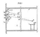
- the diagonal beam Dil belonging to the light shaft Lil which passes through the lower edge Uil of the inner window Fil and the upper edge 0ml of the entrance window Fml, includes a vertical diagonal angle ⁇ il, which is slightly larger than 90 ° and dimensioned such that this diagonal beam is no longer visible from the eye level M of a person sitting at a table T which is furthest from the window front.
- the diagonal beam Di thus delimits the area directly illuminated by a light well from an underlying blocking zone Z, which is only illuminated by daylight, which is reflective dete ceiling P and / or the vertical walls of the room has been reflected. This light produces practically no disturbing reflections on a display device G.
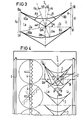
- FIG. 2 the basis is first of all that the entrance windows Fml, Fm2 and the inner windows Fil, Fi2 lie in vertical planes V, which have the transverse distance b from one another.
- the diagonal beam Dil with the diagonal angle ⁇ il is now drawn in for the lowermost light well Lil: the position of the lower edge Uil of the inner window Fil and the upper edge 0ml of the entrance window Fml is thus determined.
- the sub-reflector RUil is arranged here in such a way that the parabola according to which this reflector runs has a vertical main axis, and its focal point Bl lies in the lower edge Oml of the entrance window Fml: the diagonal beam Dil is therefore a focal point beam and thus the distance between the focal point Bl and the lower edge Uil of the inner window Fil is equal to the distance from Uil in the vertical direction from the associated guideline of the parabola. Half the distance of this guideline from the focal point Bl then gives the apex Sl.
- the focal length which is identical to the height of the entrance window Fm, is given by
- the angle of inclination ⁇ il of the flat top reflector ROil is equal to half the diagonal angle ⁇ il, both angles being measured from the vertical main axis.
- a light well is also indicated on the basis of FIG. 2, which is delimited by a sub-reflector RUi '- shown in dotted lines, the inner window Fi' lying in a plane which, with the vertical V, forms an acute angle which is open at the bottom. Obviously, with such a design, it is possible to create larger window areas with the same shielding conditions.
- the entrance window of each light well receives light from an angular range of 180 °. This can be disruptive if lower parts of the building are considered as secondary radiators. It is then expedient to limit the angular range for incident light by means of an outer light shaft placed in front of the inner light shaft, as is shown with reference to FIG. 3: inner window Fi and entry window Fm of the inner shaft Li lie - as in FIG. 2 - in two mutually parallel vertical planes V 2, the main axis Hi of the sub-reflector RUi is inclined by the main axis angle ⁇ i with respect to the vertical plane S.
- the outside light shaft La is located between an outer window Fa with the upper edge Oa and the lower edge Ua and the entry window Fm of the inside light shaft Li runs, whose focal point B lies in the upper edge 0m of the entrance window Fm and whose main axis Ha is inclined by the main axis angle ⁇ a against the vertical plane S.
- the diagonal beam Da runs through the lower edge Ua of the outer window Fa and the upper edge Om of the entrance window Fm, which includes an angle of inclination ⁇ a with the main axis Ha.
- the outside light well La only absorbs light and directs it into the inner light well, insofar as its angle of incidence lies in the angular range ⁇ a. This light is then emitted into the room in an angular range ⁇ i between the diagonal Di and the main axis Hi of the interior light well Li.
- part of a composite window is shown in cross-section, the two window panes which are parallel to one another being designated by 1 and 2.
- Shaped bodies 3 with an identical cross-section are arranged at an equal distance above one another between these panes, which are also mirror images of a vertical plane S - parallel to the window panes.
- the surfaces of the shaped bodies are designed to be reflective, in particular reflective, so that an outer light well La and an inner light well Li are formed between the superimposed shaped bodies.
- the diagonal angle 0 ⁇ for the diagonal beam D for the outside light well and the inner light well is identical to 90 ° with respect to the vertical plane S, in which the main axes of the parabolas of the lower reflectors lie: This means that the upper reflectors also have an identical inclination angle ß of 45 °.
- An arrangement with shaped bodies of this type receives light from an angular range of 90 ° - between D and S - and emits it over the same angular range - between D and S - against the ceiling and opposite walls of the room.
- a known sunshade 4 is arranged in the form of rotatable prismatic lenses, which can always be adjusted so that - regardless of the position of the sun - no sunbeam can penetrate the light wells.
Landscapes
- Life Sciences & Earth Sciences (AREA)
- Sustainable Development (AREA)
- Engineering & Computer Science (AREA)
- General Engineering & Computer Science (AREA)
- Non-Portable Lighting Devices Or Systems Thereof (AREA)
- Optical Elements Other Than Lenses (AREA)
- Blinds (AREA)
Priority Applications (1)
| Application Number | Priority Date | Filing Date | Title |
|---|---|---|---|
| AT86102960T ATE38422T1 (de) | 1985-04-30 | 1986-03-06 | Anordnung zur ausleuchtung eines raumes mit tageslicht. |
Applications Claiming Priority (2)
| Application Number | Priority Date | Filing Date | Title |
|---|---|---|---|
| DE3515603 | 1985-04-30 | ||
| DE3515603 | 1985-04-30 |
Publications (2)
| Publication Number | Publication Date |
|---|---|
| EP0200876A1 true EP0200876A1 (fr) | 1986-11-12 |
| EP0200876B1 EP0200876B1 (fr) | 1988-11-02 |
Family
ID=6269514
Family Applications (1)
| Application Number | Title | Priority Date | Filing Date |
|---|---|---|---|
| EP86102960A Expired EP0200876B1 (fr) | 1985-04-30 | 1986-03-06 | Disposition pour l'éclairage d'un local à la lumière du jour |
Country Status (8)
| Country | Link |
|---|---|
| US (1) | US4699467A (fr) |
| EP (1) | EP0200876B1 (fr) |
| JP (1) | JPS61254788A (fr) |
| AT (1) | ATE38422T1 (fr) |
| AU (1) | AU576151B2 (fr) |
| CA (1) | CA1257237A (fr) |
| DE (1) | DE3661104D1 (fr) |
| ZA (1) | ZA863221B (fr) |
Cited By (7)
| Publication number | Priority date | Publication date | Assignee | Title |
|---|---|---|---|---|
| DE4001471A1 (de) * | 1989-01-21 | 1990-07-26 | Koester Patente Gmbh | Vorrichtung fuer die herstellung einer duennen und streifenfoermigen folie an wenigstens einem traeger sowie verfahren zur herstellung einer solchen vorrichtung |
| DE4211085A1 (de) * | 1992-04-03 | 1993-10-07 | Koester Helmut | Lichtlenkelemente für Tageslicht |
| DE4310717A1 (de) * | 1993-04-01 | 1994-10-06 | Koester Helmut | Lichtlenkelemente für Tageslicht |
| DE19503293A1 (de) * | 1995-02-02 | 1996-08-08 | Spl Solar Patent Lizenz Holdin | Gekantete Jalousielamelle |
| EP0831272A1 (fr) * | 1996-09-19 | 1998-03-25 | Siemens Beleuchtungstechnik GmbH & Co. KG | Dispositif pour l'éclairage d'une pièce |
| DE202012005524U1 (de) | 2012-04-12 | 2013-07-15 | Bartenbach Holding Gmbh | Vorrichtung zur Ausleuchtung von Räumen mit Tages und/oder Kunstlicht |
| DE102014113631B3 (de) * | 2014-09-22 | 2015-11-05 | Siteco Beleuchtungstechnik Gmbh | Tageslichtsystem |
Families Citing this family (31)
| Publication number | Priority date | Publication date | Assignee | Title |
|---|---|---|---|---|
| NZ224424A (en) * | 1987-11-06 | 1990-12-21 | Ian Robert Edmonds | Light deflecting window panel: parallel cuts in transparent material by laser |
| US4820020A (en) * | 1987-11-19 | 1989-04-11 | Terrill Frank E | Passive daylighting system |
| FR2637048B1 (fr) * | 1988-09-23 | 1990-11-23 | Olivier Dominique | Dispositif d'eclairage utilisant l'energie solaire |
| AU641429B2 (en) * | 1989-09-08 | 1993-09-23 | Queensland University Of Technology | Illuminating apparatus |
| WO1991003682A1 (fr) * | 1989-09-08 | 1991-03-21 | Queensland University Of Technology | Appareil d'eclairage |
| AU657749B2 (en) * | 1992-04-23 | 1995-03-23 | Ian Robert Edmonds | Permanently fixed collimation devices which combine the function of shading and daylighting building interiors |
| US5285315A (en) * | 1992-09-25 | 1994-02-08 | Synertech Systems Corporation | Apparatus and method for optimizing useful sunlight reflected into a room |
| AT399369B (de) * | 1993-01-15 | 1995-04-25 | Bartenbach Christian | Blendschutzeinrichtung |
| DE69429113T2 (de) * | 1993-05-04 | 2002-07-25 | Redbus Serraglaze Ltd., Knowle | Zur verwendung in der verglasung geeignetes optisches bauelement |
| US5467564A (en) * | 1993-05-28 | 1995-11-21 | Andersen Corporation | Daylight collection and distribution system |
| US5408795A (en) * | 1993-05-28 | 1995-04-25 | Anderson Corporation | Daylight collection and distribution system |
| USD364469S (en) | 1994-10-13 | 1995-11-21 | Andersen Corporation | Skylight |
| USD374087S (en) | 1994-11-29 | 1996-09-24 | Andersen Corporation | Skylight |
| DE59507392D1 (de) | 1995-09-07 | 2000-01-13 | Siteco Beleuchtungstech Gmbh | Raumbeleuchtungsanordnung mit Tages- und Kunstlicht |
| EP0799654B1 (fr) * | 1996-04-02 | 2001-10-24 | Alusuisse Technology & Management AG | Produit métallique laminé comme structure déflecteur de lumière |
| US5648873A (en) * | 1996-05-30 | 1997-07-15 | Minnesota Mining And Manufacturing Company | Passive solar collector |
| US6256947B1 (en) | 1998-06-04 | 2001-07-10 | Solatube International, Inc. | Method and apparatus for a tubular skylight system |
| AU2003204904B2 (en) * | 2003-04-10 | 2006-04-27 | Ian Robert Edmonds | Light channeling window panel for shading and illuminating rooms |
| US8297786B2 (en) | 2008-07-10 | 2012-10-30 | Oree, Inc. | Slim waveguide coupling apparatus and method |
| US7843640B2 (en) * | 2008-12-16 | 2010-11-30 | Alcoa Inc. | Light shelves for daylighting |
| US8462437B2 (en) * | 2010-11-15 | 2013-06-11 | Massachusetts Institute Of Technology | Passive louver-based daylighting system |
| US8837049B2 (en) | 2012-03-26 | 2014-09-16 | Mbc Ventures, Inc. | Window blind solar energy management system |
| US8824050B2 (en) | 2012-04-06 | 2014-09-02 | Svv Technology Innovations, Inc. | Daylighting fabric and method of making the same |
| JP5914143B2 (ja) * | 2012-04-27 | 2016-05-11 | 大成建設株式会社 | 昼光照明装置 |
| CN102704818B (zh) * | 2012-05-16 | 2015-09-02 | 江苏鸿升装饰工程有限公司 | 全方位采光窗户 |
| WO2014006501A1 (fr) | 2012-07-03 | 2014-01-09 | Yosi Shani | Appareil d'éclairage au phosphore distant planaire |
| US8934173B2 (en) | 2012-08-21 | 2015-01-13 | Svv Technology Innovations, Inc. | Optical article for illuminating building interiors with sunlight |
| US20150354272A1 (en) * | 2014-06-10 | 2015-12-10 | Sergiy Vasylyev | Light-redirecting retractable window covering |
| US20160025288A1 (en) | 2014-07-25 | 2016-01-28 | Sergiy Vasylyev | Light directing sheeting and systems employing the same |
| US20170223802A1 (en) * | 2016-02-03 | 2017-08-03 | Honeywell International Inc. | Camera-aided controller of illumination |
| US11204458B2 (en) | 2018-11-12 | 2021-12-21 | S.V.V. Technology Innovations, Inc. | Wide-area solid-state illumination devices and systems employing sheet-form light guides and method of making the same |
Citations (2)
| Publication number | Priority date | Publication date | Assignee | Title |
|---|---|---|---|---|
| EP0020296A1 (fr) * | 1979-06-05 | 1980-12-10 | Relium AG | Procédé et moyen pour contrôler, dans des chambres, l'énergie rayonnante de tout le spectre |
| US4292763A (en) * | 1979-12-07 | 1981-10-06 | The United States Of America As Represented By The United States Department Of Energy | Reflective insulating blinds for windows and the like |
Family Cites Families (10)
| Publication number | Priority date | Publication date | Assignee | Title |
|---|---|---|---|---|
| DE194867C (fr) * | ||||
| US717782A (en) * | 1898-04-09 | 1903-01-06 | Pressed Prism Plate Glass Co | Illuminating structure. |
| US721256A (en) * | 1898-04-13 | 1903-02-24 | Pressed Prism Plate Glass Co | Illuminating structure. |
| US755196A (en) * | 1898-10-28 | 1904-03-22 | Pressed Prism Plate Glass Co | Illuminating structure. |
| US721259A (en) * | 1898-11-12 | 1903-02-24 | Pressed Prism Plate Glass Co | Illuminating structure. |
| US720386A (en) * | 1900-07-12 | 1903-02-10 | Pressed Prism Plate Glass Co | Illuminating prism structure. |
| CH441190A (de) * | 1965-07-16 | 1967-08-15 | Talium Ag | Verfahren zur Verbesserung der Beleuchtungsverhältnisse in Räumen mit Tageslichteinfall und Einrichtung zur Durchführung dieses Verfahrens |
| US4351588A (en) * | 1979-04-24 | 1982-09-28 | Relium Ag | Process and means for controlling the radiant energies of the entire spectral range in rooms |
| GB2141474B (en) * | 1983-06-17 | 1987-03-04 | British Res Agricult Eng | Louvred reflector |
| US4509825A (en) * | 1983-06-27 | 1985-04-09 | Hallmark Cards, Inc. | Directing and controlling the distribution of radiant energy |
-
1986
- 1986-03-06 EP EP86102960A patent/EP0200876B1/fr not_active Expired
- 1986-03-06 DE DE8686102960T patent/DE3661104D1/de not_active Expired
- 1986-03-06 AT AT86102960T patent/ATE38422T1/de not_active IP Right Cessation
- 1986-04-25 JP JP61096574A patent/JPS61254788A/ja active Pending
- 1986-04-28 CA CA000507690A patent/CA1257237A/fr not_active Expired
- 1986-04-29 AU AU56802/86A patent/AU576151B2/en not_active Ceased
- 1986-04-29 US US06/857,042 patent/US4699467A/en not_active Expired - Fee Related
- 1986-04-30 ZA ZA863221A patent/ZA863221B/xx unknown
Patent Citations (2)
| Publication number | Priority date | Publication date | Assignee | Title |
|---|---|---|---|---|
| EP0020296A1 (fr) * | 1979-06-05 | 1980-12-10 | Relium AG | Procédé et moyen pour contrôler, dans des chambres, l'énergie rayonnante de tout le spectre |
| US4292763A (en) * | 1979-12-07 | 1981-10-06 | The United States Of America As Represented By The United States Department Of Energy | Reflective insulating blinds for windows and the like |
Cited By (8)
| Publication number | Priority date | Publication date | Assignee | Title |
|---|---|---|---|---|
| DE4001471A1 (de) * | 1989-01-21 | 1990-07-26 | Koester Patente Gmbh | Vorrichtung fuer die herstellung einer duennen und streifenfoermigen folie an wenigstens einem traeger sowie verfahren zur herstellung einer solchen vorrichtung |
| DE4211085A1 (de) * | 1992-04-03 | 1993-10-07 | Koester Helmut | Lichtlenkelemente für Tageslicht |
| DE4310717A1 (de) * | 1993-04-01 | 1994-10-06 | Koester Helmut | Lichtlenkelemente für Tageslicht |
| DE19503293A1 (de) * | 1995-02-02 | 1996-08-08 | Spl Solar Patent Lizenz Holdin | Gekantete Jalousielamelle |
| EP0831272A1 (fr) * | 1996-09-19 | 1998-03-25 | Siemens Beleuchtungstechnik GmbH & Co. KG | Dispositif pour l'éclairage d'une pièce |
| DE202012005524U1 (de) | 2012-04-12 | 2013-07-15 | Bartenbach Holding Gmbh | Vorrichtung zur Ausleuchtung von Räumen mit Tages und/oder Kunstlicht |
| DE102014113631B3 (de) * | 2014-09-22 | 2015-11-05 | Siteco Beleuchtungstechnik Gmbh | Tageslichtsystem |
| EP2998499A1 (fr) | 2014-09-22 | 2016-03-23 | Siteco Beleuchtungstechnik GmbH | Systeme de lumiere du jour |
Also Published As
| Publication number | Publication date |
|---|---|
| US4699467A (en) | 1987-10-13 |
| AU576151B2 (en) | 1988-08-11 |
| EP0200876B1 (fr) | 1988-11-02 |
| JPS61254788A (ja) | 1986-11-12 |
| ATE38422T1 (de) | 1988-11-15 |
| DE3661104D1 (en) | 1988-12-08 |
| AU5680286A (en) | 1986-11-06 |
| ZA863221B (en) | 1986-12-30 |
| CA1257237A (fr) | 1989-07-11 |
Similar Documents
| Publication | Publication Date | Title |
|---|---|---|
| EP0200876B1 (fr) | Disposition pour l'éclairage d'un local à la lumière du jour | |
| EP0461137B1 (fr) | Systeme deflecteur de lumiere pour l'eclairage d'interieur | |
| EP0786623A1 (fr) | Dispositif pour éclairer une pièce à partir d'une lumiére solaire non-aveuglante et diffuse | |
| DE69514005T2 (de) | Gestufte lamelle für gerichtete lichtstrahlung | |
| DE2615379A1 (de) | Abschirmung fuer lichtoeffnungen, fenster und dergleichen | |
| EP0524388A2 (fr) | Dispositif d'éclairage naturel | |
| DE2732592A1 (de) | Schirm fuer strahlungsenergie | |
| EP0090830A1 (fr) | Dispositif de protection contre la lumiere solaire. | |
| EP0090822B1 (fr) | Fenetre ayant des barres prismatiques pare-soleil | |
| DE19543811A1 (de) | Gestufte Lamelle zur Lenkung von Lichtstrahlung | |
| EP0040853A1 (fr) | Lampe de signalisation | |
| DE19929138A1 (de) | Sonnenschutz-Jalousieanlage zur entblendeten Lichtumlenkung | |
| EP0372272B1 (fr) | Armature d'éclairage à grille réfléchissante | |
| EP0045901B1 (fr) | Armature de forme allongée pour l'éclairage d'un plan de travail | |
| DE10016587B4 (de) | Lichtlenksystem für die Kunst- und Tageslichtbeleuchtung eines Innenraumes | |
| DE3122164A1 (de) | Anordnung zur ausleuchtung eines raumes mit dachfenstern | |
| AT521340B1 (de) | Blendfreie Tageslichtlamellen-Jalousien | |
| EP1243743B1 (fr) | Lamelle pour le rideau d'un store | |
| DE1472508A1 (de) | Lichtuebertragungsplatte | |
| EP0012430B1 (fr) | Dispositif pour réduire la réflexion due à des sources externes de lumière dans les feux de circulation | |
| EP3992413B1 (fr) | Stores pliants d'obscurcissement | |
| DE19845424A1 (de) | Lichtlenkende Sonnenschutzvorrichtung | |
| DE102005029723B4 (de) | Lichtlenkfläche zum Überdecken einer lichtdurchlässigen Gebäudeöffnung | |
| AT407678B (de) | Tageslichtsteuerungssystem | |
| DE69914256T2 (de) | Lichtdurchlässiges Paneel für Gebäude, das die natürliche Helligkeit innerhalb des Gebäudes verbessert |
Legal Events
| Date | Code | Title | Description |
|---|---|---|---|
| PUAI | Public reference made under article 153(3) epc to a published international application that has entered the european phase |
Free format text: ORIGINAL CODE: 0009012 |
|
| AK | Designated contracting states |
Kind code of ref document: A1 Designated state(s): AT CH DE FR GB IT LI |
|
| 17P | Request for examination filed |
Effective date: 19861127 |
|
| 17Q | First examination report despatched |
Effective date: 19880129 |
|
| GRAA | (expected) grant |
Free format text: ORIGINAL CODE: 0009210 |
|
| AK | Designated contracting states |
Kind code of ref document: B1 Designated state(s): AT CH DE FR GB IT LI |
|
| REF | Corresponds to: |
Ref document number: 38422 Country of ref document: AT Date of ref document: 19881115 Kind code of ref document: T |
|
| GBT | Gb: translation of ep patent filed (gb section 77(6)(a)/1977) | ||
| REF | Corresponds to: |
Ref document number: 3661104 Country of ref document: DE Date of ref document: 19881208 |
|
| ET | Fr: translation filed | ||
| ITF | It: translation for a ep patent filed | ||
| PLBE | No opposition filed within time limit |
Free format text: ORIGINAL CODE: 0009261 |
|
| STAA | Information on the status of an ep patent application or granted ep patent |
Free format text: STATUS: NO OPPOSITION FILED WITHIN TIME LIMIT |
|
| 26N | No opposition filed | ||
| ITTA | It: last paid annual fee | ||
| PGFP | Annual fee paid to national office [announced via postgrant information from national office to epo] |
Ref country code: GB Payment date: 19970224 Year of fee payment: 12 |
|
| PGFP | Annual fee paid to national office [announced via postgrant information from national office to epo] |
Ref country code: FR Payment date: 19970321 Year of fee payment: 12 |
|
| REG | Reference to a national code |
Ref country code: CH Ref legal event code: PUE Owner name: SIEMENS AKTIENGESELLSCHAFT BERLIN UND MUENCHEN -DA |
|
| PG25 | Lapsed in a contracting state [announced via postgrant information from national office to epo] |
Ref country code: GB Free format text: LAPSE BECAUSE OF NON-PAYMENT OF DUE FEES Effective date: 19980306 |
|
| PG25 | Lapsed in a contracting state [announced via postgrant information from national office to epo] |
Ref country code: FR Free format text: THE PATENT HAS BEEN ANNULLED BY A DECISION OF A NATIONAL AUTHORITY Effective date: 19980331 |
|
| GBPC | Gb: european patent ceased through non-payment of renewal fee |
Effective date: 19980306 |
|
| REG | Reference to a national code |
Ref country code: CH Ref legal event code: PUE Owner name: SIEMENS BELEUCHTUNGSTECHNIK GMBH & CO. KG -DANN AN Ref country code: CH Ref legal event code: PFA Free format text: SESVENNA SECHZEHNTE VERWALTUNGSGESELLSCHAFT MBH TRANSFER- SITECO BELEUCHTUNGSTECHNIK GMBH Ref country code: CH Ref legal event code: NV Representative=s name: ISLER & PEDRAZZINI AG |
|
| REG | Reference to a national code |
Ref country code: FR Ref legal event code: ST |
|
| PGFP | Annual fee paid to national office [announced via postgrant information from national office to epo] |
Ref country code: AT Payment date: 20020313 Year of fee payment: 17 |
|
| PGFP | Annual fee paid to national office [announced via postgrant information from national office to epo] |
Ref country code: CH Payment date: 20020315 Year of fee payment: 17 |
|
| PGFP | Annual fee paid to national office [announced via postgrant information from national office to epo] |
Ref country code: DE Payment date: 20020318 Year of fee payment: 17 |
|
| PG25 | Lapsed in a contracting state [announced via postgrant information from national office to epo] |
Ref country code: AT Free format text: LAPSE BECAUSE OF NON-PAYMENT OF DUE FEES Effective date: 20030306 |
|
| PG25 | Lapsed in a contracting state [announced via postgrant information from national office to epo] |
Ref country code: LI Free format text: LAPSE BECAUSE OF NON-PAYMENT OF DUE FEES Effective date: 20030331 Ref country code: CH Free format text: LAPSE BECAUSE OF NON-PAYMENT OF DUE FEES Effective date: 20030331 |
|
| PG25 | Lapsed in a contracting state [announced via postgrant information from national office to epo] |
Ref country code: DE Free format text: LAPSE BECAUSE OF NON-PAYMENT OF DUE FEES Effective date: 20031001 |
|
| REG | Reference to a national code |
Ref country code: CH Ref legal event code: PL |
|
| PG25 | Lapsed in a contracting state [announced via postgrant information from national office to epo] |
Ref country code: IT Free format text: LAPSE BECAUSE OF NON-PAYMENT OF DUE FEES;WARNING: LAPSES OF ITALIAN PATENTS WITH EFFECTIVE DATE BEFORE 2007 MAY HAVE OCCURRED AT ANY TIME BEFORE 2007. THE CORRECT EFFECTIVE DATE MAY BE DIFFERENT FROM THE ONE RECORDED. Effective date: 20050306 |