EP0200889A2 - Electro-optical deviator for a laser - Google Patents
Electro-optical deviator for a laser Download PDFInfo
- Publication number
- EP0200889A2 EP0200889A2 EP86103486A EP86103486A EP0200889A2 EP 0200889 A2 EP0200889 A2 EP 0200889A2 EP 86103486 A EP86103486 A EP 86103486A EP 86103486 A EP86103486 A EP 86103486A EP 0200889 A2 EP0200889 A2 EP 0200889A2
- Authority
- EP
- European Patent Office
- Prior art keywords
- polarizer
- deviator
- electrooptical
- laser
- optical
- Prior art date
- Legal status (The legal status is an assumption and is not a legal conclusion. Google has not performed a legal analysis and makes no representation as to the accuracy of the status listed.)
- Withdrawn
Links
- 230000005855 radiation Effects 0.000 claims abstract description 12
- 230000010287 polarization Effects 0.000 claims abstract description 9
- 230000003287 optical effect Effects 0.000 abstract description 9
- 238000002310 reflectometry Methods 0.000 description 5
- 230000010363 phase shift Effects 0.000 description 1
Images
Classifications
-
- H—ELECTRICITY
- H01—ELECTRIC ELEMENTS
- H01S—DEVICES USING THE PROCESS OF LIGHT AMPLIFICATION BY STIMULATED EMISSION OF RADIATION [LASER] TO AMPLIFY OR GENERATE LIGHT; DEVICES USING STIMULATED EMISSION OF ELECTROMAGNETIC RADIATION IN WAVE RANGES OTHER THAN OPTICAL
- H01S3/00—Lasers, i.e. devices using stimulated emission of electromagnetic radiation in the infrared, visible or ultraviolet wave range
- H01S3/10—Controlling the intensity, frequency, phase, polarisation or direction of the emitted radiation, e.g. switching, gating, modulating or demodulating
- H01S3/101—Lasers provided with means to change the location from which, or the direction in which, laser radiation is emitted
-
- H—ELECTRICITY
- H01—ELECTRIC ELEMENTS
- H01S—DEVICES USING THE PROCESS OF LIGHT AMPLIFICATION BY STIMULATED EMISSION OF RADIATION [LASER] TO AMPLIFY OR GENERATE LIGHT; DEVICES USING STIMULATED EMISSION OF ELECTROMAGNETIC RADIATION IN WAVE RANGES OTHER THAN OPTICAL
- H01S3/00—Lasers, i.e. devices using stimulated emission of electromagnetic radiation in the infrared, visible or ultraviolet wave range
- H01S3/10—Controlling the intensity, frequency, phase, polarisation or direction of the emitted radiation, e.g. switching, gating, modulating or demodulating
- H01S3/106—Controlling the intensity, frequency, phase, polarisation or direction of the emitted radiation, e.g. switching, gating, modulating or demodulating by controlling devices placed within the cavity
- H01S3/107—Controlling the intensity, frequency, phase, polarisation or direction of the emitted radiation, e.g. switching, gating, modulating or demodulating by controlling devices placed within the cavity using electro-optic devices, e.g. exhibiting Pockels or Kerr effect
Definitions
- This invention concerns an electrooptical deviator which can modulate high power laser radiations at whatever polarisation distribution, at very high speed and rate.
- the invention fits the electrooptical frame, in particular that of fast non polarized monochrone light modulators.
- the invention herein proposes to solve the inconveniences described by means of a unique electrooptical configuration which provides:
- the modulator which is the subject of the invention and can be recognized by the dotted line enclosure, is used as a variable reflectivity output mirror for a laser cavity.
- the radiation coming from optical means N may be described as a combination of two orthogonal polarizations.
- the radiation, striking polarizer P splits into-two orthogonally polarized beams.
- the beam reflected by polarizer P covers the same optical path in the opposite direction returning, after striking M 3 , crossing PC, reflected by M 2 , onto polarizer P with a polarization distribution which also and in the same manner, depends on the voltage applied to modulator PC. If the voltage applied to the phase modulator is zero, the beams transmitted and reflected strike the polarizer again with the same polarization, therefore they will be transmitted and reflected respectively by the polarizer towards output 0. In this case, the deviator sends the whole radiation coming from N to output 0, acting as a mirror having null equivalent reflectivity.
- the deviator reflects the whole radiation coming from N back to M, acting as a mirror having the equivalent reflectivity 1 (total).
- the electroopical deviator has intermediate reflectivities between 0 and 1.
- the electrooptical deviator shows an equivalent reflectivity which varies in time at the same speed between 0 and 1.
- the proposed electrooptical deviator can provide very fast modulation (reflection-transmission) of the high power laser radiation with what- , soever polarization distribution.
- the laser device shown in Figure 1 con provide an output laser radiation considerably more powerful than what can be achieved with modultors in existence.
Landscapes
- Physics & Mathematics (AREA)
- Electromagnetism (AREA)
- Engineering & Computer Science (AREA)
- Plasma & Fusion (AREA)
- Optics & Photonics (AREA)
- Lasers (AREA)
Abstract
Description
- This invention concerns an electrooptical deviator which can modulate high power laser radiations at whatever polarisation distribution, at very high speed and rate.
- The invention fits the electrooptical frame, in particular that of fast non polarized monochrone light modulators.
- It can find applications in active optical systems (lasers) and in passive systems (optical signal processors).
- Previous solutions may be classified as belonging to three types:
- 1) mechanooptical
- 2) acousticoptical
- 3) electrooptical.
- 1. The mechano optical solution, due to its inertia moments, is unsuitable for fast modulations.
- 2. The acoustic optical solution although capable of providing switching times shorter than the mechano optical, due to the low propagation speed of sound, cannot provide very fast switching and it is also virtually impossible to obtain 100% amplitude modulation.
- 3. Existing electrooptical modulators, although very fast, can modulate only polarized light radiation.
- The invention herein proposes to solve the inconveniences described by means of a unique electrooptical configuration which provides:
- a) fast switching times
- b) almost 1COX modulation amplitude
- c) application of light radiation having whatever polarisation distribution.
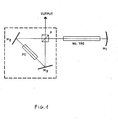
- The invention will now be described in its preferred configuration, as an illustrative example, but not confined to it, based upon the figures attached, where the modulator, which is the subject of the invention and can be recognized by the dotted line enclosure, is used as a variable reflectivity output mirror for a laser cavity.
- Here:
- M2, M3 are the modulator mirrors
- PC is the electrooptical phase modulator (e.g. a Packel cell)
- P is the polarizer (e.g. of the Mac Neillo type)
- 0 is the output direction
- N is the active means
- M is the totally reflective cavity mirror.
- In the optical configuration proposed, the radiation coming from optical means N may be described as a combination of two orthogonal polarizations. The radiation, striking polarizer P splits into-two orthogonally polarized beams.
- The one transmitted by polarizer M2, reflected by M2. and phase shifted by phase modulator PC, further reflected by M3, strikes polarizer P again with a polarization distribution which depends upon the voltage applied to phase modulator PC. The beam reflected by polarizer P covers the same optical path in the opposite direction returning, after striking M3, crossing PC, reflected by M2, onto polarizer P with a polarization distribution which also and in the same manner, depends on the voltage applied to modulator PC. If the voltage applied to the phase modulator is zero, the beams transmitted and reflected strike the polarizer again with the same polarization, therefore they will be transmitted and reflected respectively by the polarizer towards output 0. In this case, the deviator sends the whole radiation coming from N to output 0, acting as a mirror having null equivalent reflectivity.
- If the voltage (Vπ) applied to the modulator is equal to a π phase shift, the transmitted and reflected beams strike the polarizer with inverted polarization, therefore they will be reflected and transmitted toward active means N. In this case the deviator reflects the whole radiation coming from N back to M, acting as a mirror having the equivalent reflectivity 1 (total).
- Clearly, for intermediate voltages applied to the phase modulator PC, the electroopical deviator has intermediate reflectivities between 0 and 1.
- When the voltage applied to phase modulator PC varies between 0 und Vπ rapidly, the electrooptical deviator shows an equivalent reflectivity which varies in time at the same speed between 0 and 1.
- As can be understood from the description, the proposed electrooptical deviator can provide very fast modulation (reflection-transmission) of the high power laser radiation with what- , soever polarization distribution.
- The laser device shown in Figure 1 con provide an output laser radiation considerably more powerful than what can be achieved with modultors in existence.
Claims (2)
Applications Claiming Priority (2)
| Application Number | Priority Date | Filing Date | Title |
|---|---|---|---|
| IT4782585 | 1985-03-18 | ||
| IT8547825A IT1226810B (en) | 1985-03-18 | 1985-03-18 | HIGH-SPEED AND CADENCE ELECTRO-OPTIC DIVERTER WITH HIGH SPEED LASER RADIATION, HAVING ANY DISTRIBUTION OF POLARIZATION |
Publications (2)
| Publication Number | Publication Date |
|---|---|
| EP0200889A2 true EP0200889A2 (en) | 1986-11-12 |
| EP0200889A3 EP0200889A3 (en) | 1989-01-04 |
Family
ID=11262755
Family Applications (1)
| Application Number | Title | Priority Date | Filing Date |
|---|---|---|---|
| EP86103486A Withdrawn EP0200889A3 (en) | 1985-03-18 | 1986-03-14 | Electro-optical deviator for a laser |
Country Status (2)
| Country | Link |
|---|---|
| EP (1) | EP0200889A3 (en) |
| IT (1) | IT1226810B (en) |
Cited By (2)
| Publication number | Priority date | Publication date | Assignee | Title |
|---|---|---|---|---|
| EP0249580A3 (en) * | 1986-05-28 | 1989-02-08 | SELENIA INDUSTRIE ELETTRONICHE ASSOCIATE S.p.A. | Electrooptical configuration for the generation of ultrashort laser pulses |
| US7031352B2 (en) | 2000-09-13 | 2006-04-18 | Powerlase Limited | Pulse laser resonator |
Family Cites Families (5)
| Publication number | Priority date | Publication date | Assignee | Title |
|---|---|---|---|---|
| AU5376979A (en) * | 1978-12-15 | 1980-06-26 | Commonwealth Of Australia, The | Thermally compensated laser |
| GB2046937B (en) * | 1979-04-09 | 1983-05-18 | Crosfield Electronics Ltd | Optical intensity modulators |
| US4413342A (en) * | 1980-11-20 | 1983-11-01 | Quantronix Corporation | Method and apparatus for frequency doubling a laser beam |
| FR2506530A1 (en) * | 1981-05-22 | 1982-11-26 | Thomson Csf | COHERENT RADIATION SOURCE GENERATING AN ADJUSTABLE SPREAD DIRECTION BEAM |
| DE3339370A1 (en) * | 1983-10-29 | 1985-05-09 | Meditec GmbH, 8501 Heroldsberg | PULSE LASER FOR MEDICAL APPLICATIONS |
-
1985
- 1985-03-18 IT IT8547825A patent/IT1226810B/en active
-
1986
- 1986-03-14 EP EP86103486A patent/EP0200889A3/en not_active Withdrawn
Cited By (3)
| Publication number | Priority date | Publication date | Assignee | Title |
|---|---|---|---|---|
| EP0249580A3 (en) * | 1986-05-28 | 1989-02-08 | SELENIA INDUSTRIE ELETTRONICHE ASSOCIATE S.p.A. | Electrooptical configuration for the generation of ultrashort laser pulses |
| US7031352B2 (en) | 2000-09-13 | 2006-04-18 | Powerlase Limited | Pulse laser resonator |
| US7082145B2 (en) | 2000-09-13 | 2006-07-25 | Powerless Limited | Pulse laser resonator |
Also Published As
| Publication number | Publication date |
|---|---|
| EP0200889A3 (en) | 1989-01-04 |
| IT1226810B (en) | 1991-02-19 |
| IT8547825A0 (en) | 1985-03-18 |
Similar Documents
| Publication | Publication Date | Title |
|---|---|---|
| GB1363143A (en) | Polarization independent light modulation means using birefringent crystals | |
| US4059759A (en) | Passive and active pulse stacking scheme for pulse shaping | |
| US10353054B2 (en) | Laser radar device | |
| US4361911A (en) | Laser retroreflector system for identification of friend or foe | |
| US4740986A (en) | Laser resonator | |
| US6137619A (en) | High-speed electro-optic modulator | |
| US4498179A (en) | Modulated infrared laser with two coupled cavities | |
| US4504121A (en) | Interferometric multimode fiber optic switch and modulator | |
| EP0138452A2 (en) | Laser light source device | |
| US5034627A (en) | Power laser generator with control of the direction of emission of the output beam | |
| US4546477A (en) | Pulse transmission or reflection mode laser | |
| US4053763A (en) | Method and apparatus for pulse stacking | |
| EP0095563B1 (en) | Opto-optical light deflector | |
| Pepper | Hybrid phase conjugator/modulators using self‐pumped 0°‐cut and 45°‐cut BaTiO3 crystals | |
| EP0116630B1 (en) | Laser amplifier buffer | |
| US3393955A (en) | Light frequency shifter | |
| US4105953A (en) | Chirped acousto-optic Q switch | |
| EP0200889A2 (en) | Electro-optical deviator for a laser | |
| US5172382A (en) | Ultrahigh frequency optical self-modulator | |
| GB1203628A (en) | Ring laser | |
| US4318591A (en) | Polarization switched image rotator | |
| CA1166734A (en) | Unpolarised electro-optically q-switched laser | |
| GB1096167A (en) | An internal-modulation type optical maser device with a birefringence prism | |
| US3437951A (en) | Modulating or q-switching a laser | |
| US4921335A (en) | Optical phase conjugate beam modulator and method therefor |
Legal Events
| Date | Code | Title | Description |
|---|---|---|---|
| PUAI | Public reference made under article 153(3) epc to a published international application that has entered the european phase |
Free format text: ORIGINAL CODE: 0009012 |
|
| AK | Designated contracting states |
Kind code of ref document: A2 Designated state(s): AT BE CH DE FR GB LI NL SE |
|
| RIN1 | Information on inventor provided before grant (corrected) |
Inventor name: GIULIANI, GIAMPIERO Inventor name: BENEDETTI MICHELANGELI, GLAUCO Inventor name: PENCO, EUGENIO Inventor name: PALANGE, ELIA |
|
| PUAL | Search report despatched |
Free format text: ORIGINAL CODE: 0009013 |
|
| AK | Designated contracting states |
Kind code of ref document: A3 Designated state(s): AT BE CH DE FR GB LI NL SE |
|
| 17P | Request for examination filed |
Effective date: 19890630 |
|
| 17Q | First examination report despatched |
Effective date: 19910305 |
|
| STAA | Information on the status of an ep patent application or granted ep patent |
Free format text: STATUS: THE APPLICATION IS DEEMED TO BE WITHDRAWN |
|
| 18D | Application deemed to be withdrawn |
Effective date: 19911003 |
|
| RIN1 | Information on inventor provided before grant (corrected) |
Inventor name: PALANGE, ELIA Inventor name: BENEDETTI MICHELANGELI, GLAUCO Inventor name: PENCO, EUGENIO Inventor name: GIULIANI, GIAMPIERO |