EP0200939B1 - Emissionscomputertomographievorrichtung - Google Patents
Emissionscomputertomographievorrichtung Download PDFInfo
- Publication number
- EP0200939B1 EP0200939B1 EP86104813A EP86104813A EP0200939B1 EP 0200939 B1 EP0200939 B1 EP 0200939B1 EP 86104813 A EP86104813 A EP 86104813A EP 86104813 A EP86104813 A EP 86104813A EP 0200939 B1 EP0200939 B1 EP 0200939B1
- Authority
- EP
- European Patent Office
- Prior art keywords
- radiation
- subject
- detector
- effective field
- radiation detector
- Prior art date
- Legal status (The legal status is an assumption and is not a legal conclusion. Google has not performed a legal analysis and makes no representation as to the accuracy of the status listed.)
- Expired
Links
- 238000002591 computed tomography Methods 0.000 title claims description 14
- 230000005855 radiation Effects 0.000 claims description 34
- 238000001514 detection method Methods 0.000 description 5
- 238000010586 diagram Methods 0.000 description 3
- 238000003384 imaging method Methods 0.000 description 3
- 238000003745 diagnosis Methods 0.000 description 2
- 238000001914 filtration Methods 0.000 description 2
- 230000035945 sensitivity Effects 0.000 description 2
- 230000006866 deterioration Effects 0.000 description 1
- 230000005251 gamma ray Effects 0.000 description 1
- 238000000034 method Methods 0.000 description 1
- 238000009206 nuclear medicine Methods 0.000 description 1
- 230000009897 systematic effect Effects 0.000 description 1
Images

Classifications
-
- G—PHYSICS
- G01—MEASURING; TESTING
- G01T—MEASUREMENT OF NUCLEAR OR X-RADIATION
- G01T1/00—Measuring X-radiation, gamma radiation, corpuscular radiation, or cosmic radiation
- G01T1/29—Measurement performed on radiation beams, e.g. position or section of the beam; Measurement of spatial distribution of radiation
- G01T1/2914—Measurement of spatial distribution of radiation
- G01T1/2985—In depth localisation, e.g. using positron emitters; Tomographic imaging (longitudinal and transverse section imaging; apparatus for radiation diagnosis sequentially in different planes, steroscopic radiation diagnosis)
-
- A—HUMAN NECESSITIES
- A61—MEDICAL OR VETERINARY SCIENCE; HYGIENE
- A61B—DIAGNOSIS; SURGERY; IDENTIFICATION
- A61B6/00—Apparatus or devices for radiation diagnosis; Apparatus or devices for radiation diagnosis combined with radiation therapy equipment
- A61B6/02—Arrangements for diagnosis sequentially in different planes; Stereoscopic radiation diagnosis
- A61B6/03—Computed tomography [CT]
- A61B6/037—Emission tomography
Definitions
- This invention relates to an emission computed tomography apparatus for obtaining a scintigram of a subject dosed with radioisotope (RI).
- RI radioisotope
- Prior art emission computed tomography apparatuses use an Anger type gamma camera for detecting gamma rays emitted from the interior of a subject (human patient) under examination.
- the gamma camera head is rotated stepwise or continuous about the subject to collect gamma rays emitted therefrom in 360-degree directions.
- the gamma ray detection data is processed to reconstruct a tomogram image representing an RI distribution of the subject.
- the gamma camera head has a parallel-hole collimator mounted on the front side thereof. Because of the property of the collimator, the resolution of detection is reduced with an increase in the distance between the collimator and subject. With the prior art emission computed tomography apparatus as disclosed, for example, in document USA4 445 035, therefore, the gamma camera head is moved along an elliptical orbit centered at a body axis of the subject, in order to move the camera head as close to the subject as possible so as to improve the detection resolution.
- Prior art document EP-A-0 092 437 discloses a radiation imaging system including a rotatable scintillation detector for non-circular emission computed tomography.
- the radiation imaging system comprises a rotatable scintillation detector and a linearly movable detector stand. With the stand stationary, the scintillation detector is capable of circularly orbiting about the longitudinal axis of the patient for emission computed tomography and with the detector stationary the detector stand may be linearly displaced for whole body scanning with the patient aligned parallel to the detector stand path in an orientation orthogonal to the tomographic orientation.
- the circular rotational motion is combined with the linear translation such that the detector orbits about a section of the patient in a non-circular path. The path assures a minimum distance between the face of the scintillation detector and the boundary of the patient during the entire tomographic orbit to thereby improve resolution of the tomogram.
- Position signals from the detectors are inputted to position signal mixing circuits to control them by means of the control signal of the unblank signal mixing circuit. Additionally, an inversion buffer is mounted, and mixing position signals are outputted to display them by means of the first signal and the mixing position signals. In this way, sensitivity of an image from one of these both detectors is corrected by an image from the other detector.
- the present invention provides an emission computed tomography apparatus as defined in claim 1 or claim 2.
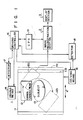
- an emission computed tomography apparatus comprises a detection section 1, image reconstruction section (data processing section) 2 and display section 3.
- Detection section 1 has a gantry 11 which supports a detector (gamma camera head) 12 so as to be capable of being rotated about a subject 13 lying on a couch (not shown) as shown at 12a and 12b, and can be moved in directions of arrows X, as shown at 11a a and 11b.
- detector driving means 14 is provided for rotating detector 11 about subject 13 and gantry driving means 15 for moving gantry 11 in the directions of arrows X. Both driving means 14 and 15 are controlled by driving controller 16.
- the rotational angle of detector 12 is detected by detector 17, and the length of movement of gantry 11 is detected by detector 18.
- Detectors 17 and 18 are coupled to driving controller 16.
- Detector 12 detects gamma rays emitted from subject 13 while rotating thereabout either continuously or stepwise at an angle of 10 degrees, for instance.
- Output data of detector 12 (which is X, Y position signals) is fed to image reconstruction section 2 to produce tomogram information signals representing RI distribution of the subject.
- the tomogram information signals are fed to display section 3 for visually displaying a tomogram of the subject.
- Driving controller 16 and image reconstruction section 2 are coupled to central processing unit (CPU) 19, to control gantry 11 and detector 12 and perform image processing in image reconstruction section 2.
- CPU central processing unit
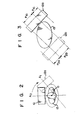
- detector 12 is driven along a circular orbit by driving means 14. Since gantry 14 is moved in the directions of arrows X, detector 12 is effectively moved along an elliptical orbit about the subject, as shown in Fig. 2. As seen in Fig. 2, when detector 12 is positioned in front of subject 13, a line AO passing through the center of the effective field of view of detector 12 passes through the body axis 0 of subject 13. However, when the detector is moved as shown at 12a, the center line A1 of the effective field of view no longer passes through the body axis 0 of subject 13. A portion of the subject under examination thus goes out of the effective field of view of the detector. This means that the portion of the subject cannot be detected.
- the invention intends to compensate the reduction in the effective field of view of the detector.
- the enlarging compensation of the effective field of view of detector will now be described with reference to Fig. 4.
- the Figure shows profiles 41 and 42 of projection data collected by the detector at the corresponding positions shown in Fig. 3.
- the region where 360-degree direction data of the subject can be collected is only a region enclosed in circle 43 from the ground discussed above. Therefore, data profile 41 lacks data represented by c', while data profile 42 lacks data represented by d'.
- lacking data c' of data profile 41 is approximately interpolated with data c of data profile 42 collected at the opposed position.
- lacking data d' of data profile 42 is approximately interpolated with data d of data profile 41.
- the effective field of view of the detector can be regarded to be enlarged, so that a substantially perfect reconstructed image may be obtained.
- step S51 image data is collected. This is performed while detector 12 is either continuous or stepwise rotated, and moving gantry 11 in the directions of arrows X. Collected image data (i.e., slice data) at each position of the detector is stored in a magnetic disk file in image reconstruction section 2. Image data collected at opposed positions of the detector can be discriminated in the magnetic disk file.
- step S52 data collected at opposite positions of the detector are extracted from the magnetic disk file. It is to be noted that the size of the region where 360-degree direction data can be collected, i.e., region 43 in Fig. 4, is known in advance. In other words, data region corresponding to region 43 in the slice data is known in advance.
- step S53 image data P1b and P2b corresponding to region 43 are extracted from the opposite data and added together in CPU 19.
- the effective field of view is compensated in CPU 19.
- CPU 19 performs an arithmetic operation given by where K1 and K2 are coefficients which are introduced to smoothly join image areas corresponding to P2a and P1c to an image area corresponding to (P2b+Pl b).
- K1 and K2 are coefficients which are introduced to smoothly join image areas corresponding to P2a and P1c to an image area corresponding to (P2b+Pl b).
- coefficient K2 is obtained from a relation
- Image data obtained after the compensation of the effective field of view is filed in the magnetic disk file (step S55).
- the image data stored in the magnetic disk file is subjected to filtering (i.e., convolution) (step S56).
- the image data is back projected to obtain the reconstructed image data (i.e. a tomogram representing the RI distribution).
- the reconstructed image is displayed on display section 3 (step S58).
Landscapes
- Health & Medical Sciences (AREA)
- Life Sciences & Earth Sciences (AREA)
- Engineering & Computer Science (AREA)
- Physics & Mathematics (AREA)
- High Energy & Nuclear Physics (AREA)
- Molecular Biology (AREA)
- Medical Informatics (AREA)
- Nuclear Medicine, Radiotherapy & Molecular Imaging (AREA)
- Biomedical Technology (AREA)
- Spectroscopy & Molecular Physics (AREA)
- General Physics & Mathematics (AREA)
- Optics & Photonics (AREA)
- Pathology (AREA)
- Radiology & Medical Imaging (AREA)
- Biophysics (AREA)
- Heart & Thoracic Surgery (AREA)
- Surgery (AREA)
- Animal Behavior & Ethology (AREA)
- General Health & Medical Sciences (AREA)
- Public Health (AREA)
- Veterinary Medicine (AREA)
- Nuclear Medicine (AREA)
Claims (3)
dadurch gekennzeichnet, daß

Applications Claiming Priority (2)
| Application Number | Priority Date | Filing Date | Title |
|---|---|---|---|
| JP60078029A JPH0652301B2 (ja) | 1985-04-11 | 1985-04-11 | エミツシヨンct装置 |
| JP78029/85 | 1985-04-11 |
Publications (2)
| Publication Number | Publication Date |
|---|---|
| EP0200939A1 EP0200939A1 (de) | 1986-11-12 |
| EP0200939B1 true EP0200939B1 (de) | 1989-11-02 |
Family
ID=13650381
Family Applications (1)
| Application Number | Title | Priority Date | Filing Date |
|---|---|---|---|
| EP86104813A Expired EP0200939B1 (de) | 1985-04-11 | 1986-04-08 | Emissionscomputertomographievorrichtung |
Country Status (4)
| Country | Link |
|---|---|
| US (1) | US4692624A (de) |
| EP (1) | EP0200939B1 (de) |
| JP (1) | JPH0652301B2 (de) |
| DE (1) | DE3666739D1 (de) |
Families Citing this family (10)
| Publication number | Priority date | Publication date | Assignee | Title |
|---|---|---|---|---|
| US4888486A (en) * | 1988-09-20 | 1989-12-19 | Picker International, Inc. | Scanning nuclear camera with automatic orbit shape modification |
| US5043890A (en) * | 1989-06-12 | 1991-08-27 | General Electric | Compensation of computed tomography data for objects positioned outside the field of view of the reconstructed image |
| IL96230A0 (en) * | 1990-11-02 | 1991-08-16 | Elscint Ltd | Gantry for nuclear medicine imaging systems |
| US5811813A (en) * | 1990-12-06 | 1998-09-22 | Elscint Ltd. | Dual detector gamma camera system |
| US5338936A (en) * | 1991-06-10 | 1994-08-16 | Thomas E. Kocovsky, Jr. | Simultaneous transmission and emission converging tomography |
| US5528042A (en) * | 1995-06-14 | 1996-06-18 | Siemens Medical Systems, Inc. | Retrospectively determining the center of rotation of a scintillation camera detector from SPECT data acquired during a nuclear medicine study |
| FR2736163B1 (fr) * | 1995-06-29 | 1997-08-22 | Sopha Medical | Methode d'obtention, en medecine nucleaire, d'une image du corps d'un patient corrigee des troncatures |
| US6949747B2 (en) * | 2000-06-02 | 2005-09-27 | Is2 Medical Systems Inc. | Apparatus and method for automatically adjusting the path of a medical camera |
| GB0128361D0 (en) * | 2001-11-27 | 2002-01-16 | British Nuclear Fuels Plc | Improvements in and relating to instruments |
| US7095030B2 (en) * | 2001-11-27 | 2006-08-22 | British Nuclear Fuels Plc | Investigations of radioactivity |
Family Cites Families (5)
| Publication number | Priority date | Publication date | Assignee | Title |
|---|---|---|---|---|
| US3970853A (en) * | 1975-06-10 | 1976-07-20 | The United States Of America As Represented By The United States Energy Research And Development Administration | Transverse section radionuclide scanning system |
| JPS53673A (en) * | 1976-06-24 | 1978-01-06 | Shintarou Takeuchi | Incinerator |
| US4434369A (en) * | 1981-01-02 | 1984-02-28 | Raytheon Company | Radiographic camera |
| JPS57184988A (en) * | 1981-05-09 | 1982-11-13 | Toshiba Corp | Scintillation camera device |
| US4503331A (en) * | 1982-04-21 | 1985-03-05 | Technicare Corporation | Non-circular emission computed tomography |
-
1985
- 1985-04-11 JP JP60078029A patent/JPH0652301B2/ja not_active Expired - Fee Related
-
1986
- 1986-04-08 EP EP86104813A patent/EP0200939B1/de not_active Expired
- 1986-04-08 DE DE8686104813T patent/DE3666739D1/de not_active Expired
- 1986-04-10 US US06/850,048 patent/US4692624A/en not_active Expired - Lifetime
Also Published As
| Publication number | Publication date |
|---|---|
| JPH0652301B2 (ja) | 1994-07-06 |
| DE3666739D1 (en) | 1989-12-07 |
| EP0200939A1 (de) | 1986-11-12 |
| JPS61235781A (ja) | 1986-10-21 |
| US4692624A (en) | 1987-09-08 |
Similar Documents
| Publication | Publication Date | Title |
|---|---|---|
| EP0569238B1 (de) | Verfahren zur Bildrekonstruktion für ein Computertomographiegerät | |
| EP1848985B1 (de) | Multimodus-röntgenabbildungssystem mit flachbildschirm | |
| US7113569B2 (en) | X-ray CT apparatus | |
| US6370218B1 (en) | Methods and systems for determining x-ray beam position in multi-slice computed tomography scanners | |
| US5923038A (en) | Partial angle tomography scanning and reconstruction | |
| US7154988B2 (en) | X-ray computed tomographic imaging apparatus | |
| US6147353A (en) | Image shift for gamma camera | |
| US7103233B2 (en) | Methods and apparatus for determining component alignment | |
| EP0426464A2 (de) | Rechnergesteurtes tomographisches Bildrekonstruktionsverfahren für Spiralabtasten | |
| EP0744158B1 (de) | Computertomograph-Abtastgerät | |
| US6040580A (en) | Method and apparatus for forming multi-dimensional attenuation correction data in tomography applications | |
| JP4452844B2 (ja) | 被曝を低減したコンピュータ断層撮影イメージング方法及び装置 | |
| US6751283B2 (en) | Reconstruction method for tilted-gantry computed tomography | |
| US4433427A (en) | Method and apparatus for examining a body by means of penetrating radiation such as X-rays | |
| JP2002148340A (ja) | 診断画像形成用核医学ガンマ線カメラ及びそれを用いた診断画像形成方法 | |
| WO2007110795A2 (en) | Effective dual-energy x-ray attenuation measurement | |
| US5998792A (en) | Positron emission tomography with variable detector geometry | |
| US20040114708A1 (en) | Method for imaging in the computer tomography of a periodically moved object to be examined and CT device for carrying out the method | |
| US6381297B1 (en) | High pitch reconstruction of multislice CT scans | |
| US6429433B1 (en) | Continuous rotation sampling scheme for transmission radiation corrected gamma cameras | |
| JPH0720245A (ja) | ポジトロンct装置 | |
| US6269139B1 (en) | Methods and apparatus for pre-filtering weighting in image reconstruction | |
| US4692624A (en) | Emission computed tomography apparatus | |
| JP3089050B2 (ja) | Spect画像の再構成方法 | |
| US6418183B1 (en) | Methods and apparatus for two-pass CT imaging |
Legal Events
| Date | Code | Title | Description |
|---|---|---|---|
| PUAI | Public reference made under article 153(3) epc to a published international application that has entered the european phase |
Free format text: ORIGINAL CODE: 0009012 |
|
| 17P | Request for examination filed |
Effective date: 19860505 |
|
| AK | Designated contracting states |
Kind code of ref document: A1 Designated state(s): DE NL |
|
| 17Q | First examination report despatched |
Effective date: 19880329 |
|
| GRAA | (expected) grant |
Free format text: ORIGINAL CODE: 0009210 |
|
| AK | Designated contracting states |
Kind code of ref document: B1 Designated state(s): DE NL |
|
| REF | Corresponds to: |
Ref document number: 3666739 Country of ref document: DE Date of ref document: 19891207 |
|
| PLBE | No opposition filed within time limit |
Free format text: ORIGINAL CODE: 0009261 |
|
| STAA | Information on the status of an ep patent application or granted ep patent |
Free format text: STATUS: NO OPPOSITION FILED WITHIN TIME LIMIT |
|
| 26N | No opposition filed | ||
| PGFP | Annual fee paid to national office [announced via postgrant information from national office to epo] |
Ref country code: DE Payment date: 20050331 Year of fee payment: 20 |
|
| PGFP | Annual fee paid to national office [announced via postgrant information from national office to epo] |
Ref country code: NL Payment date: 20050403 Year of fee payment: 20 |
|
| PG25 | Lapsed in a contracting state [announced via postgrant information from national office to epo] |
Ref country code: NL Free format text: LAPSE BECAUSE OF EXPIRATION OF PROTECTION Effective date: 20060408 |
|
| NLV7 | Nl: ceased due to reaching the maximum lifetime of a patent |
Effective date: 20060408 |